BOOLEAN OPERATIONS
The guard is becoming frustrated again. "Primitives may be easy to create, but what can you do with them?"
Your job is going to be to help him combine primitives to create more complex shapes. Primitives (Box, Wedge, Pyramid, Cylinder, Cone, Sphere, Torus and Polysolid) are the basic building blocks of solid modeling. These predetermined shapes can be combined using Boolean operations to form more complex shapes. You can find these primitive forms under the BOX icon in the Modeling toolset or you can call them in the Command Line.

Training
Union, Subtract, and Intersect- Launch AutoCAD.
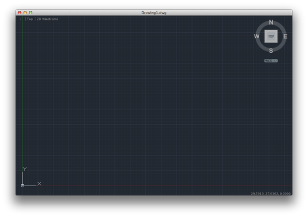
- Create a new drawing. Select File>New Drawing:

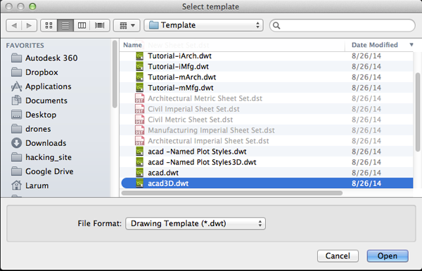
- Instead of selecting the acad.dwt template, select the acad3D.dwt template file and press the Open button to continue to the drawing screen.

- Set your units to millimeters. Set your FACETRES to 10.
- Create 2 layers. One for a box and one for a sphere:

- Make the box layer active:

- On the box layer create a box of any size. Call the BOX command. Specify the first corner or Center. Specify the other corner or [Cube/Length]. Specify height or [2Point].
- Make the sphere layer active. On the sphere layer create a sphere that intersects with the box. To create a sphere type SPHERE. Specify the center or [2P, 3P, TTr]. If you need to move your sphere. Type MOVE and select your sphere. Specify base point or [Displacement]. Specify Second point or <use first point as Displacement>

- Call COPY. Select the box and sphere. Specify base point or [Displacement mOde]. Specify Second point or [Array] <use first point as Displacement> and make 2 more copies.

- Click on the first set of box and sphere. Right click and select Isolate>Isolate Objects from the context menu:

Union
UNION is a command to combine solid objects together. Interestingly enough, the solids do not need to touch or even intersect each other to be unioned together. When your objects do touch or intersect, you'll notice that the edges will be sewn at the new intersection points of the unioned objects.-
Make the the layer that you want the unioned object to reside on active:

- Type UNI and press <RETURN> to invoke the UNION command.
- Click on one of the objects in the active layer:
- Click on the other object or objects in the non-active layer.
- Press <RETURN>

Subtract
The SUBTRACT command allows you to remove one or more solids from another solid. This operation is known in other programs as a boolean difference. To use SUBTRACT you first select the object you want to keep, then select that which you want to remove.- Isolate the middle box and sphere. You will have to Right+click in the drawing, select Isolate, Select end Object Isolation, and then isolate the the middle box and sphere.
- Type SUBTRACT and press <RETURN>:

- Select the object you want to keep and press <RETURN>

- Select the object you want to subtract and press <RETURN>


- Save your drawing.
Intersect
Intersect is called when you want to create a new solid from the space that the selected solids share:- Isolate the last box and sphere.

- Type Intersect and press <RETURN>:

- Select the objects that intersect or overlap.

- Press <RETURN>:

- End isolation.
- Save drawing.
Quest
The guard is still confused. He gets how the Boolean operations work, but he doesn't see how can they be used to construct objects.Your quest is as follows: By the end of the day create an object that is made with boolean operations and present it to the guard.
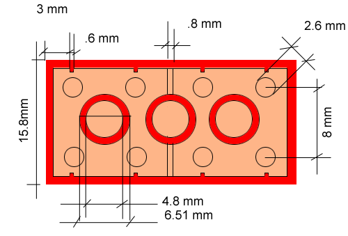
Look at the list and images below if you need some inspiration:
- rings
- gift boxes
- vases
- game pieces
- toys
- puzzles
- construction pieces
- connectors
- coin traps
- pill boxes
- fixtures
- lamps
Source:
Cross, Nigel. Engineering Design Methods. Chichester: Wiley, 1989.
Omura, George; Graham, Richard (Rick) (2010-11-09). Mastering AutoCAD for Mac (Kindle Location 18101). Wiley. Kindle Edition.
Shih, Randy H. AutoCAD 2014 Tutorial Second Level: 3D Modeling. Mission, KS: SDC Publications, 2013. Print.
Shumaker, Terence M., and David A. Madsen. AutoCad and Its Applications: Basics. Tinley Park, IL: Goodheart-Willcox, 2004. Print.
Watson, David. "Learn AutoCAD with Our Free Tutorials." AutoCAD Tutorials, Articles & Forums. N.p., n.d. Web. 05 Jan. 2015.


