Extruding
The guard is beginning to understand. But his next question for you is "What about curves and handles. How do I do that with primitives and Boolean operations?"
The answer is you can't. At least you can't do it with just Boolean operations. There is still much to learn. The next thing you should learn is the command EXTRUDE. Complex models can be created by applying thickness to 2D profiles. The process of adding thickness to profiles is referred to as extruding. The EXTRUDE command allows you to create extrusions from lines, arcs, polylines, splines, ellipses, 2D solids, regions, and 3D solid faces. While you can extrude all of these objects only the closed shapes or solid objects (polylines, regions, and 2D solids) will create solid, printable extrusions. Open-ended objects, like lines and arcs will produce surface extrusions (extrusions with no mass properties).
You can extrude a profile a specified height or you can choose to extrude a profile along a path.
A REGION is a closed 2D solid. You can create any closed shape with the drawing tools and then convert that closed shape to a region. The region is 2D because it has no thickness, but it is still a solid shape. This means that you can apply Boolean operations to REGIONS. When regions are unioned, subtracted, or intersected, a composite region, or region model is created. You can also EXTRUDE or PRESSPULL a region to make 3D objects. This is pretty cool because it means you can create any closed shape and extrude it perpendicular to the plane or along a path.
Training
- Launch AutoCAD.
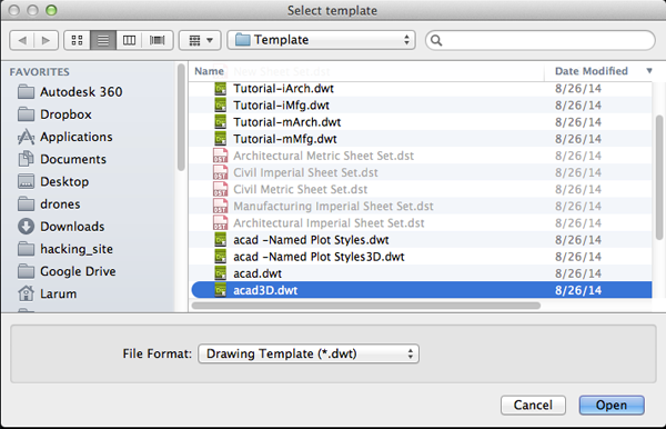
- Create a new drawing. Select File>New Drawing:
- Select the acad3D.dwt template file and press the
Open button to continue to the drawing screen.
- Type UN and select UN (UNITS):
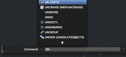
- Set your units to millimeters and FACETRES to 10.
- Type VSCURRENT or VS and press <RETURN>. This command will allow you to set the visual style in the current viewport.
- Type E and press <RETURN> to set the visual style to shaded with edges.
- Create a pyramid with 8 sides and align the first edge with coordinates (0,0) and (0,4). Set the height to 6.

- Type EXTRUDE and press <RETURN>.

- CTRL+click on one of the faces to select it and press <RETURN>:

- Set the height of the extrusion to 2 and press <RETURN>:

- RIGHT+click on the drawing and select Repeat EXTRUDE:

- Extrude each of the eight faces by 2:

- When you are done, type UNI and press <RETURN>. Select all the objects and press <RETURN> to create a single object.
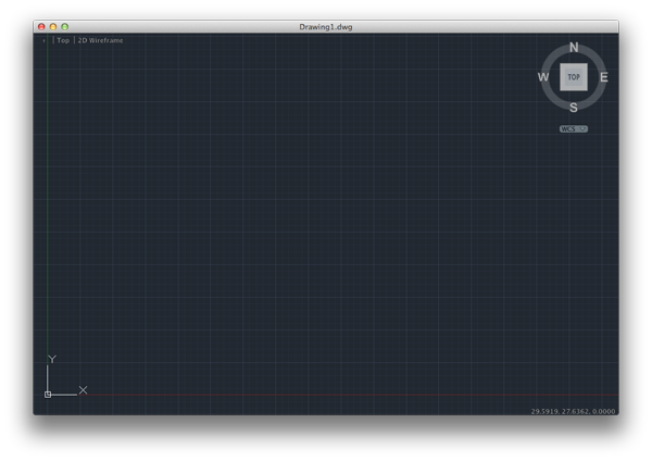
- In the upper right hand corner of your drawing is the View Cube. As you move your cursor over the cube, planes and edges are highlighted. Clicking on a highlighted plane selects it and changes the view to the selection. Use the View Cube to change the view to TOP. Make sure N is at the top. Click on the arrows on the right side of the cube to rotate the view if necessary.
- DELOBJ is a system variable that controls whether geometry used to create other objects is retained or deleted. Type DELOBJ and press <RETURN>. Set the value to 0. This will ensure that your original paths will not be deleted when you extrude.
- Call the circle command and create a circle centered at (12,0) with a diameter of 2.

- Use the View Cube to rotate the view to FRONT.

- Click on the WCS and select New UCS:

- Type V and press <RETURN> to set the plane to the current view.

- Now adjust the view by clicking and pulling the View Cube so that you can still see the circle.
- Call the SPLINE command and draw the first point near the circle. Keep clicking to create the curve. RIGHT click and select ENTER to end the curve. A SPLINE is a smooth curve that passes through or near specified points. You can edit your spline curves after they are drawn by clicking on the handles or type SPE to edit the curve with more control:

- Call EXTRUDE and press <RETURN>.
- Type MOde and press <RETURN> (You actually only need to type the capitalized letters)
- Type SOlid or SO and press <RETURN>,
- Click on the circle and press <RETURN>.

- Type P for Path and press <RETURN>.
- Click on the spline.

- Some interesting things about EXTRUDE:
- If your spline was positioned away from the circle, during the extrusion it would move back to the circle:


- If the spline was on an angle, you might end up with unexpected results:


- If your spline was positioned away from the circle, during the extrusion it would move back to the circle:
- Create a new layer and name it Extrusions.
- Select the pyramid and the extruded tube and change the active layer to Extrusions.
- Make layer 0 active and turn off Extrusions.

- Click on WCS to reset the view:

- Make two copies of the spline and move them to the right

- You can create a profile using closed splines (press c to close the curve when you are drawing).

- Create a circle next to the third Spline. Type REGION to invoke the REGION command and select the circle. If conversion is successful, the shape will turn light gray.

- Create an intersecting circle and convert that to a region too:

- Once you have regions you can use SUBTRACT, UNION or INTERSECT.


- You can extrude each of these profiles along a path:

- You can also perform a straight extrude by not using a path:

-
You can also use EXTRUDE on face subobjects along a path. Create a BOX. Call EXTRUDE, CTRL+click on the top face to extrude, specify the taper angle or path if desired, and specify the extrusion height. The resulting extrusion will become a new solid. If you want a single solid you will need to call UNION.


- Move the extruded shapes onto the Extrusions layer.
- Create another layer named Paths and Profiles. Move the remaining paths and profiles onto that layer. Make 0 the active layer and turn off Paths and Profiles.
- Change the view to the default view by clicking on the home icon near the View Cube.
- Make a circle centered at (0,0) with a diameter of 15.
- Select the line tool and draw the shape with the following coordinates:
- (15,0)
- (@12,0)
- (@0,5)
- (@-2,-2)
- (@-2,6)
- (@-2,0)
- (@-1,-1)
- (@0,3)
- (@-1,0)
- c
- Convert the shape to a REGION.
- Call 3DROTATE and press <RETURN>.
- Select the REGION.
- Specify the base point by clicking on (15,0)
- Click on the red circle. It should change color. Type 90 and press <RETURN>.
- Call EXTRUDE and select the Region. Type p for Path and then select the circle:

- Move the extruded shape to the Extrusions layer.
- Move the REGION on to the Paths and Profiles layer.
- Here is an example or an region with a SPLINE curve extruded along the path of an eight-sided polygon:

- Save your work.
PRESSPULL
PRESSPULL allows you to extrude any closed boundary. The closed boundary can be a flat surface, closed polyline, circle or region. You can use this command to add to or subtract from an existing solid. The extrusion is always applied perpendicular to the boundary plane.- If you have a primitive with a sketch you can call PRESSPULL:

- Select the boundary area:

- Pull down to make a hole, pull up to make a cylinder

- The end result is a hole:

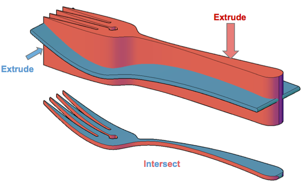
Image from Todd Blatt at Tinkerine.com
Source:
Cross, Nigel. Engineering Design Methods. Chichester: Wiley, 1989.
Omura, George; Graham, Richard (Rick) (2010-11-09). Mastering AutoCAD for Mac (Kindle Location 18101). Wiley. Kindle Edition.
Shih, Randy H. AutoCAD 2014 Tutorial Second Level: 3D Modeling. Mission, KS: SDC Publications, 2013. Print.
Shumaker, Terence M., and David A. Madsen. AutoCad and Its Applications: Basics. Tinley Park, IL: Goodheart-Willcox, 2004. Print.
Watson, David. "Learn AutoCAD with Our Free Tutorials." AutoCAD Tutorials, Articles & Forums. N.p., n.d. Web. 05 Jan. 2015.