Lofting
"But what if I don't want to create something symmetrical?"
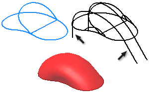
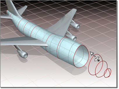
That's where the LOFT command comes in. It allows you to connect profiles in order to make a solid. You can still create symmetrical models with LOFT, but you don't have to. Tell the guard that you'll show him what you mean by the end of the day. The LOFT command creates solids based on a series of cross-sectional profiles. Solids can be created by lofting just the cross sections, the cross sections with a path or the cross sections with a guide curve. Once you call the command, you are prompted to select the profiles. Make sure that you select each profile in the order that you want to loft them.
Training
- Launch AutoCAD.
- Create a new drawing using the 2D drawing template. Set the units to millimeters, the FACETRES to 10.
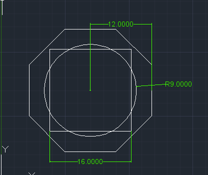
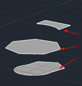
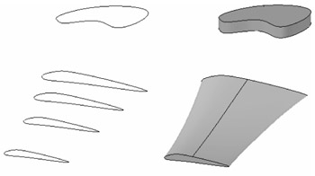
- Create 3 closed shapes similar in size to the the ones below.
A convenient way to get a square centered on a specific point is to use the POLYGON command with the sides set to 4. If you want the length of the edge of your 4-sided polygon to be a particular length, use circumscribed and set the radius to half the length that you want.
- Rotate your view:
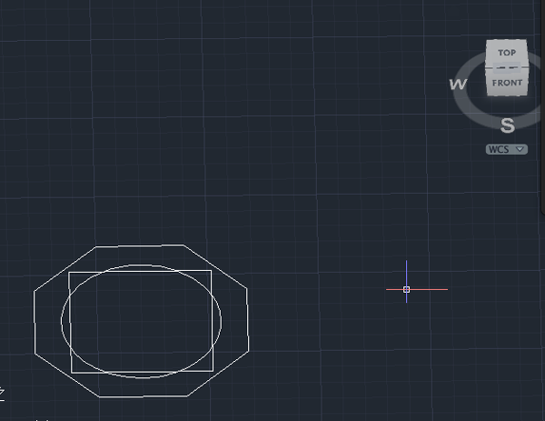
- Move two of your shapes up from the ground plane. Call MOVE. Select a shape. Select a displacement point. Enter relative coordinates, like @0,0,24 to move the shape up 24 units:

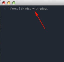
- Call VSCURRENT and change the style to Shaded with edges:
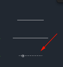
- Call the LOFT command and then click on the bottom cross section:
- Click on the center cross section:
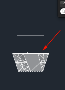
- Click on the top cross section and then press <RETURN>:
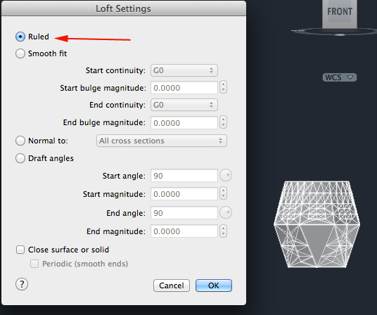
- Type S for Settings and select Ruled:
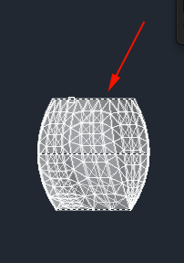
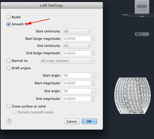
- Click on Smooth fit:
- Click on Normal to:
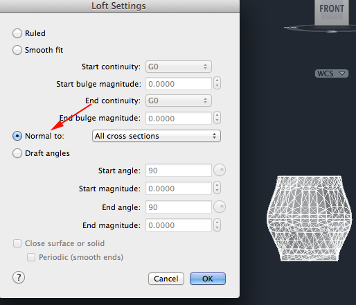
- Click on Draft angles:
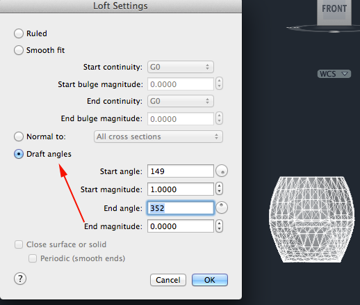
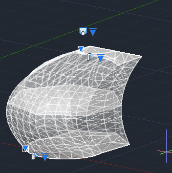
- Select one of the options you have viewed and press the OK button.
- Create three regions and separate them vertically. Call LOFT and click on the three cross sections:
- Press <RETURN> to complete the loft:
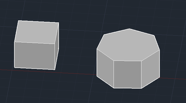
- Create two solids:
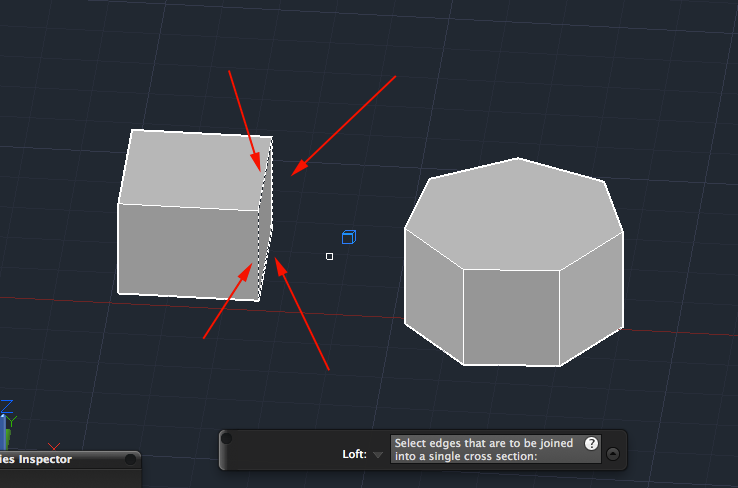
- If you want to loft the edges of 3D objects you will need to call Join multiple edges. Call LOFT and type J to Join edges. Click on each of the edges of the face of one solid and press <RETURN>:
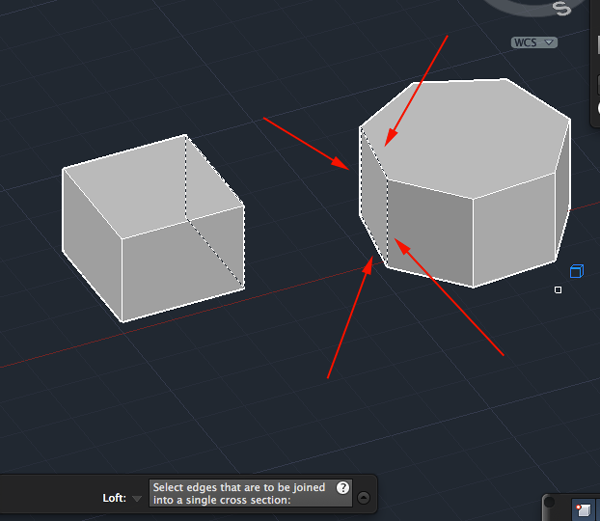
- Type J again. Click on each of the edges of a face of the other solid and press <RETURN>:
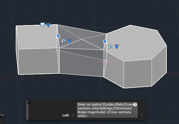
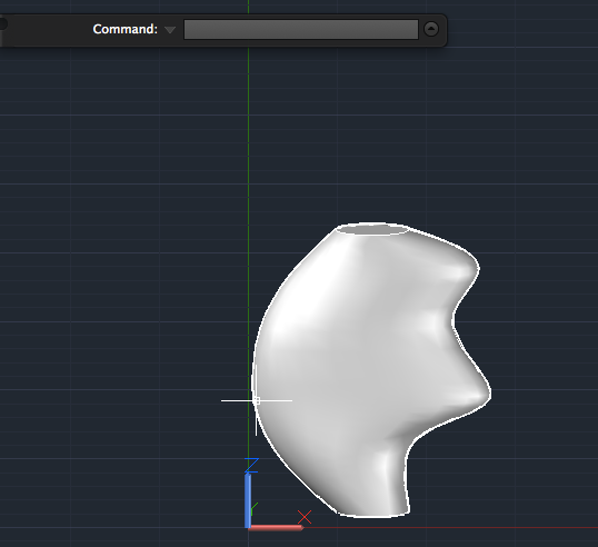
- RIGHT+click and select ENTER to loft the two solids:
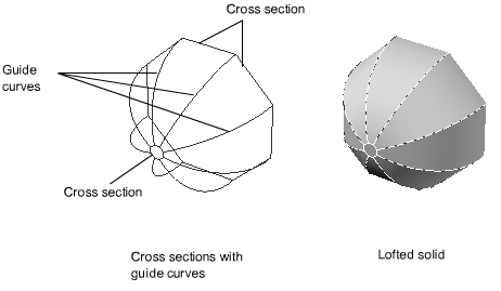
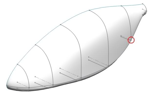
- Guide curves are lines that control the shape of the transition between the cross sections. Guide curves must start on the first cross section, end on the last and intersect any that fall in between. The surface controls must be set to Smooth Fit.
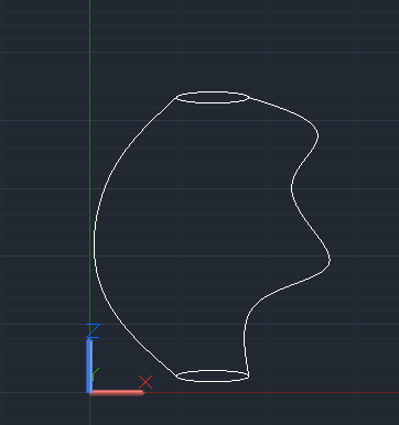
Create two circles separated vertically and connect them with two splines:
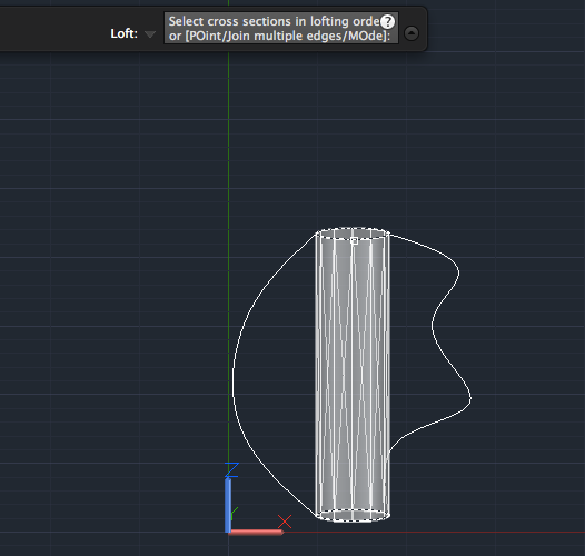
- Call LOFT and click on both circles. Press <RETURN>:
- Press G for Guide and click on one of the splines:
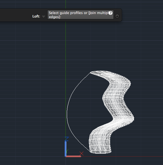
- Click on the other spline:
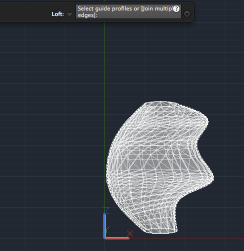
- Press <RETURN> to complete the loft:
In the solid below, the second guide was a line instead of a spline: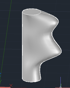
Quest
Create an object that is made with loft and present it to the guard. You can also add boolean operations, extrusions, and revolves.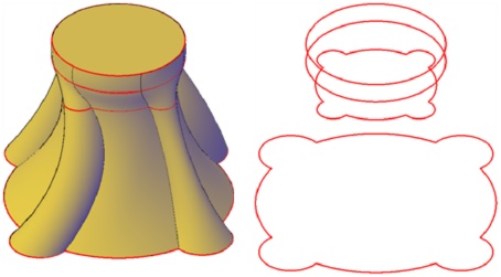


Source:
Cross, Nigel. Engineering Design Methods. Chichester: Wiley, 1989.
Omura, George; Graham, Richard (Rick) (2010-11-09). Mastering AutoCAD for Mac (Kindle Location 18101). Wiley. Kindle Edition.
Shih, Randy H. AutoCAD 2014 Tutorial Second Level: 3D Modeling. Mission, KS: SDC Publications, 2013. Print.
Shumaker, Terence M., and David A. Madsen. AutoCad and Its Applications: Basics. Tinley Park, IL: Goodheart-Willcox, 2004. Print.
Watson, David. "Learn AutoCAD with Our Free Tutorials." AutoCAD Tutorials, Articles & Forums. N.p., n.d. Web. 05 Jan. 2015.