Add this line in the head section:
<script src='https://cdn.firebase.com/v0/firebase.js'></script>
Firebase references are created using a URL that specifies which data you want to access.
A core concept of Firebase is that every piece of data has its own URL. You can use this URL to access your data in several ways:
<script src='https://cdn.firebase.com/v0/firebase.js'></script>
Firebase references are created using a URL that specifies which data you want to access.
A core concept of Firebase is that every piece of data has its own URL. You can use this URL to access your data in several ways:
- From any Firebase client library
- From our REST API
- By entering it in any browser (Try clicking the link above).
Tutorial:
https://www.firebase.com/tutorial/#tutorial/basic/0Adding Remote Control
The power of Electric Imp is in connecting your appliances to the internet. You are now going to add a remote control so the blinking may be controlled from the Planner.
The Planner and impees pass data to-and-fromeach other via connections referred to as input and output ports. From the imp's perspective an input accepts data sent from the Planner to the imp, while an output is the reverse. In this program you will only be concerned with the input port - a channel through which you can control operation of our LED.
To use the remote control, you will have to edit your blink program by adding an inhibit variable which, when set, will cause the blink function to switch off the LED and exit without setting a new wakeup timer. From that moment there will be no further blink activity until something happens to re-enable it.
-
Click edit to edit your blinking code.
- Add a new variable:
// Variable to represent LED inhibit state
inhibit <- 0;
- Modify the blink function so that now the contents of the function look like this:
if(inhibit){ // Blinking inhibited, turn off the LED hardware.pin9.write(0); }else{ // Change state ledState = ledState?0:1; server.show(ledState); // Reflect state to the pin hardware.pin9.write(ledState); // Schedule the next state change imp.wakeup(0.1, blink); } - Define a class to represent your input port. You'll derive from the InputPort class and specify a data type of number. Zero will switch off blinking, and non-zero will switch it on.
Set two member variables to give the port a name (which is displayed in the Planner to help with connecting nodes together) and define the data type. Alternatively these parameters can have been passed to the class constructor.
The InputPort class has a method set which is called when data arrives from the Planner. Override this method with your own implementation which will set or clear the inhibit flag depending on the value received. When you clear the flag (enable the LED) you also call blink to re-start the LED blinking.// input class for LED control channel class input extends InputPort{ name = "LED control" type = "number" function set(value){ if(value == 0){ // 0 = Inhibit LED operation inhibit = 1; }else{ // 1 = Enable LED operation inhibit = 0; blink(); } } } - Modify imp.configure. Remember earlier that there were two empty arrays? The first is an array of InputPort instances, and the second an array of OutputPort instances. Use these arrays to create as many communication channels as you require in each direction. In this case you need just the one input.
// Register with the server imp.configure("Blink-O-Matic", [input()], []); - Save the code, run it and click on Planner
- If the LED does not stop blinking unplug and replug
- Click Add Node and add a tick tock.
- Connect the nodes
Analog Input
You might want to create an application that has the imp to read an analog voltage on one of its pins. Each pin can be configured as an ADC (Analog to Digital Converter), which outputs a 16-bit value. The imp can read a voltage between 0 V (which will produce an output of 0) and the imp's supply voltage (usually 3.3V, occasionally slightly lower; this will produce an output of 65,535).
If you need to determine the supply voltage of the imp, it can be done in firmware:
local supplyVoltage = hardware.voltage()
- Wire up a potentiometer so that the right most lead connects to 3V, the leftmost wire connects to GND and the center lead connects to a ADC pin, lets say 7.
- Create a new program and name it.
- The first line should be a comment with the name of the program
- Next, you'll need to configure the 7 pin as an analog input :
hardware.pin7.configure(ANALOG_IN);
- Create a function called checkPot that will do three things:
-
Read the voltage on the pin and save it to a variable:
local rawValue = hardware.pin7.read(); -
Format the result (in this case, scale the number so that the output is a float between 0 and 1)
// check if this value is "different enough" from the last one so you don't send the same value over and over if (math.abs(rawValue - lastRawValue) > 150) { // divide by 65535.0 to get a value between 0.0 and 1.0 local potValue = rawValue / 65535.0; lastRawValue = rawValue; server.show(potValue); } - Schedule the function to run again
imp.wakeup(0.01, checkPot);
-
Read the voltage on the pin and save it to a variable:
- Register with the imp service and call your function for the first time
imp.configure("Potentiometer", [], []); checkPot(); - Save, run replug in your device. Click on Planner tab
- Click the settings button to change your firmware.
PWM
Microcontrollers cannot produce varrying voltages. They produce a high (In the case of the imp 3.3V) and a low (0V). But you can "fake" analog output by using pulsewidth modulation. Just like animation creates the illusion of movement, pulsewidth modulation, manipulates the intervals bewtween on (the pulsewidth) and off in such a way that it fools the eye and appears to be between on and off.

PWM signals are often used to control servo motors, other devices, and the brightness of LEDs.
A pulse-width modulated signal sends pulses of constant frequency, but varies the duty cycle (ratio of time on to time off). By driving an LED with this signal, it is possible to take advantage of persistence of vision (POV) to make the LED appear brighter or dimmer.
The imp is capable of producing a PWM signal on any of the user-accessible pins. For this example, the imp will output a PWM signal on pin 9. The LED will be powered by the 3.3V supply from the April board, and the imp will sink current from the LED on pin 9. When the voltage on pin 9 is high, the LED will be off; when the voltage is low, the LED will be on.
LED forward voltage is approximately 1.8V
Supply voltage is 3.3V
V = IR
I = 4 mA (0.004 A)
The voltage applied to the LED is therefore 3.3V - 1.8V = 1.5V
R = V/I = 1.5V / 0.004 A = 375Ω
the program
- Configure pin 9 as a PWM output
- Read in a value - this example will use an Input Port to get a value from the planner.
- Set the duty cycle of the PWM output based on the value received
- Open the Code tab, create a new program, name it and comment out a line that names the program
- To configure pin 9 as a PWM output, there are three arguments that must be dealt with:
- Mode: PWM_OUT
- Period in seconds (1/frequency)
- Duty cycle (a floating point number between 0 and 1, where 1 is 100% duty cycle)
Note that a %100 duty cycle turns the LED completely off; pin 9 will stay high and no current will flow through the LED.
hardware.pin9.configure(PWM_OUT, 1.0/500.0, 1.0);
- Take in a value from the planner by creating an Input Port. This is done by extending the InputPort base class. The set method of this new class will receive input sent to an object of this class by default; implement the set method to take in a value and perform an action.
class ledBrightness extends InputPort{
    name = "LED Brightness"
    type = "number"

    function set(value) {
        // write a floating point number between 0.0 and 1.0, where 1.0 = 100% duty cycle
        server.log(value);
        //LED's brightness is inversely related to the duty cycle
        hardware.pin9.write(1.0-value);
    }

}
Setting the duty cycle of the PWM signal is extremely straightforward. When a pin is configured as a PWM output, calling write with a floating point number between 0 and 1 sets the duty cycle of the output signal appropriately.
The set method in the InputPort will be called any time new data arrives on the input port, so there is no need to implement a loop or schedule updates within this firmware. - Outside the new input port class definition, register with the imp service. Make sure the input port is included in the array of input ports (the second argument) in imp.configure.
imp.configure("Brightness Controller", [ledBrightness], []); - Save it, run it, navigate to Planner
- Under firmware, select the program. After a second or two, you will see the node update and the label will change to “ Brightness Controller”. Note that the LED will be off when initialized and will remain off until a value is sent to the imp.
- Add a Tick Tock node and connect it to your program
Servo Motors
Servo motors are motors whose position can be set via a pulse-width modulated signal
The imp can output a PWM signal on any pin, and you can change the duty cycle of that signal, making it easy to control servos.
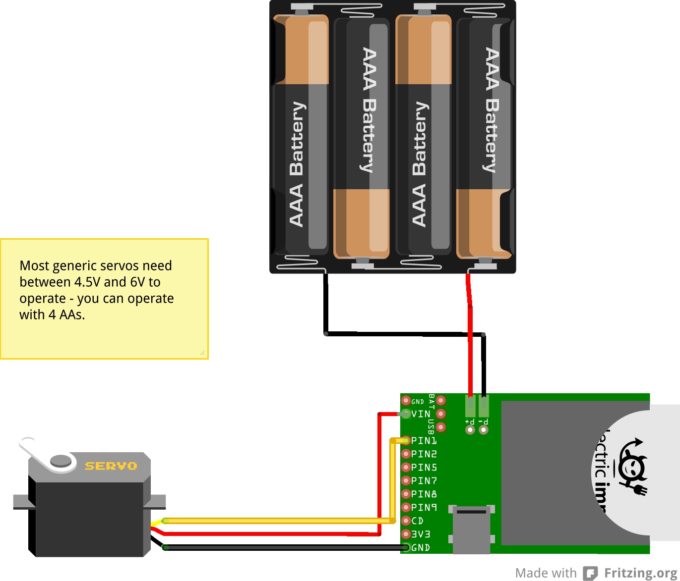
For this example, the imp will control the position of a single servo motor. The imp will take in a floating-point value between 0 and 1 via an Input Port, then use that value to set the position of the servo motor.
In this application, the power supply is slightly more important; most generic servos operate at supply voltages between 4.5V and 6V, so 2 AA batteries will be insufficient.
- Create a new program, name it and include a comment that names the program in the first line.
- Configure the pin as a PWM output.
- Mode: PWM_OUT
- Period in seconds (1/frequency)
- Duty cycle (a floating point number between 0 and 1, where 1 is 100% duty cycle)
Configure pin 9 as a PWM output. Note that the duty cycle is initialized to 8.5% (1.7 ms) to set the motor position to the center.hardware.pin1.configure(PWM_OUT, 0.02, 0.085);
- Take in a value from the planner by creating an Input Port. Extend the InputPort base class. The set method of this new class will receive input sent to an object of this class by default; implement the set method to take in a value and perform an action.
class servo extends InputPort{ name = "servo position" type = "number" function set(value) { server.log(value); // scale the duty cycle we set on the pin so that 0 = fully counter clockwise and 1 = fully clockwise hardware.pin1.write(0.04 + (value * 0.09)); } } - When a pin is configured as a PWM output, calling write with a floating point number between 0 and 1 sets the duty cycle of the output signal appropriately.
The set method in the InputPort will be called any time new data arrives on the input port, so there is no need to implement a loop or schedule updates within this firmware. - Register with the imp service. Note that the input port is included in the array of input ports (the second argument) in imp.configure.
imp.configure("Servo Controller", [servo], []); - Save, go to planner, set up firmware, connect a Tick Tock Node.
- Use a second imp with a potentiometer to control the servo.
Creating Input Ports
Creating Input Ports You can create as many input ports on your imp as you like. Input ports can be all different types, with different actions to take when new data is received, or many instances of one or several classes of input port that you might define.
To create an input port, write a class definition that extends the InputPort base class. You'll need three things to make a functional input port:
- A type member, which will be displayed on the planner when you're making connections. This should describe the sort of data you want to take in with this input port (float, integer, degrees, command, etc.)
- A name member, which will be shown as the name of the input port on the planner when you're making connections. For example, servo position, message, or LED brightness.
- An implementation of the set function, which will be called when new data is sent to your input port. The set function describes what to do with this new data.
class Servo extends InputPort{

    type = "float"
    name = "position"

    function set(value) {
        hardware.pin1.write(0.04 + (value * 0.09));
    }
}
class Servo extends InputPort{
    type = "float"
    pin = null

    // define a constructor so that you can construct seperate instances for servos 1 and 2
    constructor(name, pin) {
        // call through to the base (InputPort) constructor with the provided name
        base.constructor(name)
        this.pin = pin
       // here you might like to configure the pin, if you didn't already do that at global scope
    }

    function set(value) {
        this.pin.write(0.04 + (value * 0.09));
    }
}
With the constructor included in the definition, input port objects could be constructed right at imp.configure:
imp.configure("April Dual Servo Controller", [Servo("Pan", hardware.pin1), Servo("Tilt", hardware.pin2)], []);
Creating Output Ports
Just like with input ports, you can create as many output ports on your imp as you like. Output port construction is done in a single line of code, with a single argument, and actually emitting data is done with the output port's set method.To create an output port, simply set a local variable to the value returned from the OutputPort constructor. The constructor takes one argument: the name of your new output port.
local my_output = OutputPort("potentiometer");
my_output.set(value);
HL2y1GV48bLVpxD9EjSHoTKFu92SAKxML0M5dFAxWEk5cz0g
125313
