projection()
A conic section is a curve obtained as the intersection of a cone with a plane. A conic consists of those points whose distances to some point, called a focus, and some line, called a directrix, are in a fixed ratio, called the eccentricity.Traditionally, the three types of conic section are the hyperbola, the parabola, and the ellipse. The type of a conic corresponds to its eccentricity, those with eccentricity less than 1 being ellipses, those with eccentricity equal to 1 being parabolas, and those with eccentricity greater than 1 being hyperbolas. In the focus-directrix definition of a conic the circle is a limiting case with eccentricity 0 (wikipedia)
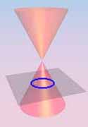
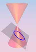
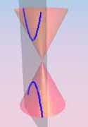
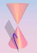
Images from math2.org/math/algebra/conics.htm
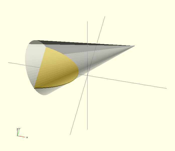
OpenSCAD does not have a 2D primitive for creating ellipses, hyperbolas or parabolas, but there is a way to do this. OpenSCAD's projection() statement allows you to create 2d drawings from 3d models. You can use these forms in your models or export them to the dxf format. The process works by projecting a 3D model to the (x,y) plane, with z at 0. If cut=true, only points with z=0 will be considered (effectively cutting the object). Setting cut to false will consider all the points above and below the plane and will create a proper projection.
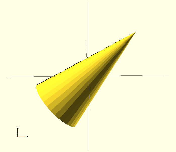
cone(0,45,0,0,0,10);
module cone(rotx=0,roty=0,rotz=0,x=0,y=0,z=0){
    rotate( a=[rotx,roty,rotz] ) {
    translate([x,y,z])
    cylinder( r1=25, r2=0, h=100, center=true );
   }
}
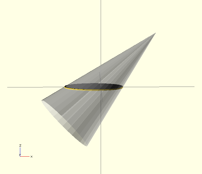
Adding projection():
projection( cut=true ) {
cone(0,45,0,0,0,10);
}

%cone(0,45,0,0,0,10);
module cone(rotx=0,roty=0,rotz=0,x=0,y=0,z=0){
    rotate( a=[rotx,roty,rotz] ) {
    translate([x,y,z])
    cylinder( r1=25, r2=0, h=100, center=true );
   }
}
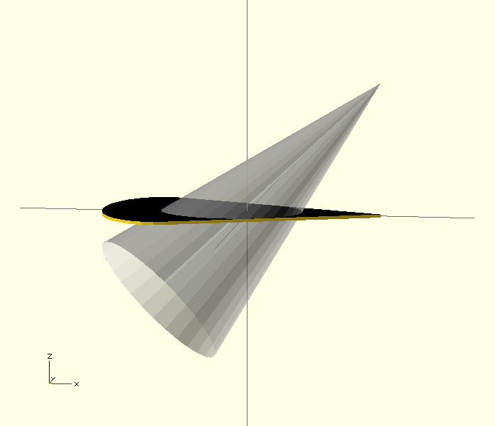
If you set cut to false OpenSCAD will project the entire object to a 2D outline. projection() projects the 3D object onto the Z plane, the two dimentional plane created by the X and Y axes.
If you set cut to false you will notice that the projection of the cone looks like a flattened 3D cone as seen from above.
Adding projection() where cut=false:
projection( cut=false ) {
cone(0,45,0,0,0,10);
}

%cone(0,45,0,0,0,10);
module cone(rotx=0,roty=0,rotz=0,x=0,y=0,z=0){
    rotate( a=[rotx,roty,rotz] ) {
    translate([x,y,z])
    cylinder( r1=25, r2=0, h=100, center=true );
   }
}
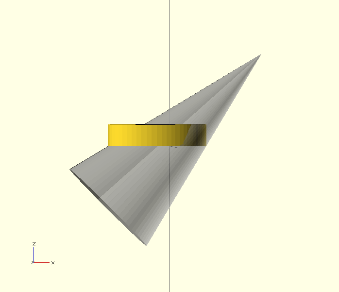
When you set the cut to true you should have noticed that you ended up with an ellipse. Circles, ellipses, parabolas, and hyperbolas are all slices of a cone. The OpenSCAD 2D primitive circle() can only make circles, so if you need an ellipse you can use projection() to create the shape you need:
$fn=64;
linear_extrude(height=10)
projection( cut=true ) {
cone(0,45,0,0,0,10);
}

%cone(0,45,0,0,0,10);
module cone(rotx=0,roty=0,rotz=0,x=0,y=0,z=0){
    rotate( a=[rotx,roty,rotz] ) {
    translate([x,y,z])
    cylinder( r1=25, r2=0, h=100, center=true );
   }
}
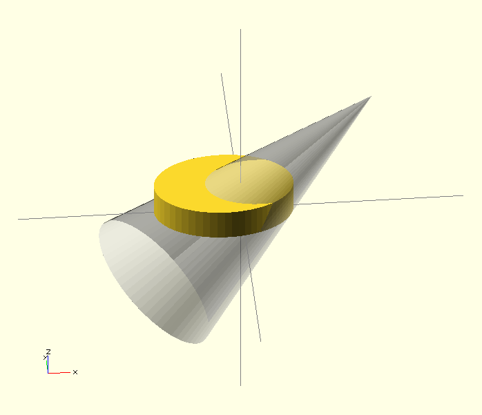
In the code below, the order of transforms is switched:
$fn=64;

projection( cut=true ) {
cone(0,45,0,0,0,25);
}

%cone(0,45,0,0,0,25);
module cone(rotx=0,roty=0,rotz=0,x=0,y=0,z=0){
    translate([x,y,z]){
    	  rotate( a=[rotx,roty,rotz] ) {
          cylinder( r1=25, r2=0, h=100, center=true );
	  }
    }
}
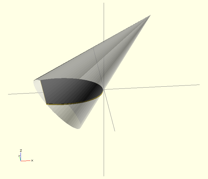
By translating before rotating you are altering where you are taking the Z plane slice from. If the cone were tilted slightly more (and were infinitely long), the result would be a hyperbola:
$fn=64;

projection( cut=true ) {
cone(0,60,0,0,0,25);
}

%cone(0,60,0,0,0,25);
module cone(rotx=0,roty=0,rotz=0,x=0,y=0,z=0){
    translate([x,y,z]){
    	  rotate( a=[rotx,roty,rotz] ) {
          cylinder( r1=25, r2=0, h=100, center=true );
	  }
    }
}
