AutoCAD
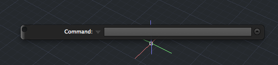
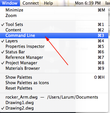
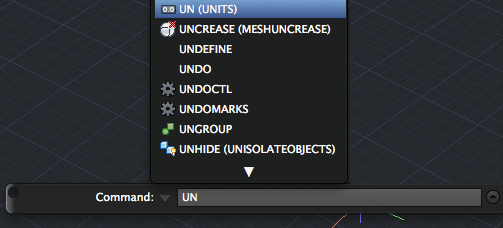
AutoCAD may be different from any application you have used in the past. Instead of dragging-and-dropping, you will use the command line to create your drawings.
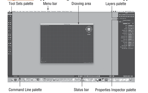
Image from Omura, George; Graham, Richard (Rick) (2010-11-09). Mastering AutoCAD for Mac (Kindle Location 669). Wiley. Kindle Edition.
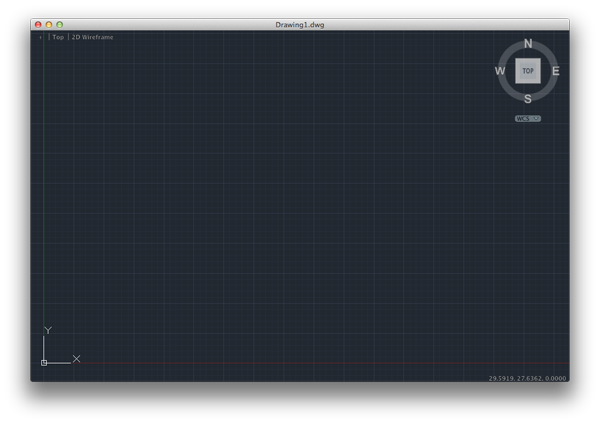
All objects drawn in AutoCAD are placed on a simple X,Y coordinate system. In AutoCAD this is known as the World Coordinate System (WCS).
AutoCAD uses coordinates (x,y) to determine where an object is located. A line to the right of the the first point is on the positive X-axis. A line straight up from the first point is on the positive Y-axis.
A line has two points, a start point and an end point. AutoCAD works with the points to display the line on the screen.
Most of the time you will not have an indication of where the origin is. Often you will draw a new line starting from the endpoint of an existing line. To do this you use relative points. In order to tell AutoCAD that the next point is relative to the the previous point, you need to use the @ symbol (shift+2).
ABSOLUTE POINTS are exact points on the drawing space.
RELATIVE POINTS are relative to an object in the drawing space.
It's a simple system, but mastering it is the key to working with AutoCAD.
Angles are another important aspect to AutoCAD. But watch out, AutoCAD measures angles in a particular way:
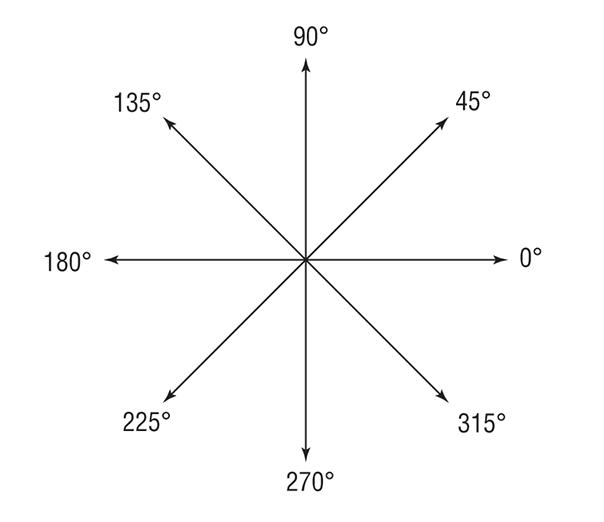
In order to figure out the angle, you need to know that
- 0° is at the 3 o'clock position.
- 180° is at the 9 o'clock position.
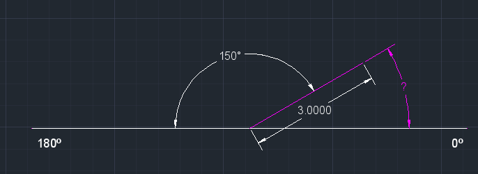
- The angle between 180° and the line you want to draw is 150°.
- The length of the line you want to draw is 3 segments long.
Here's how:
- Start at the 0° position and measure counter-clockwise (+) to 180°.
- From 180°, measure clockwise 150° (-)
- Consider that you just went +180-150 and use that as an equation: +180-150=30
- Now you can draw your line by first creating a start point and then using relative positioning for the second point (polar coordinates):
or
@segment_length<angle value
@3<30
- ABSOLUTE COORDINATES—Using this method, you specify the points as they relate to the origin of the WCS. To specify a point just specify in the exact point as X,Y. So if you wanted to start the line 5 units to the right of the origin and 10 units up, you would type 5,10 and press <RETURN>
- RELATIVE COORDINATES—This allows you to specify points in relation to the first point you have entered. After you've entered one point, the next would be entered as @X,Y. This means that AutoCAD will draw a line from the first point to another point X units over and Y units up relative to the previous point.
- POLAR COORDINATES—You can use this system if you know that you want to draw a line a certain distance at a particular angle. You would specify this as @D<A, where D is the distance and A is the angle. Example: @10<90 will draw a line 10 units straight up from the first point.
Basic AutoCAD Terminology
World Coordinate System (WCS) |
This is the common X-Y coordinate system that is the default. If it is modified, it becomes a User Coordinate System (UCS) |
Absolute coordinates |
A way of inputting points based on AutoCAD's origin. |
Relative coordinates |
A way of inputting points based on a starting point. |
Polar coordinates |
A way of inputting points based on distance and angle. |
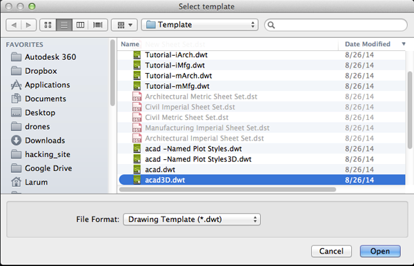
acad.dwt |
This is the default template that automatically loads whenever you start a drawing session. It can be customized to suit your needs. Templates are files that contains preset values for frequently used settings. The file extension is DWT. |
Crosshair |
This is your cursor when it is in the drawing space. |
Extents |
The outer boundaries of the objects you have drawn. |
Grid |
This is the pattern of dots displayed on the screen to guide you. It can be toggled on and off by pressing the F7 key. |
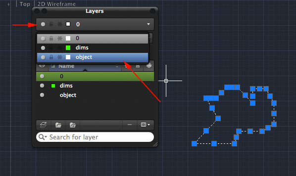
Grips |
Small 'handles' on objects that allow for quick editing. |
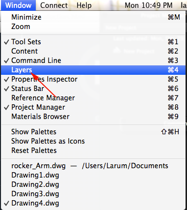
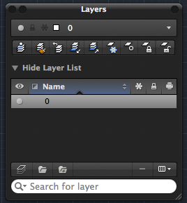
Layer |
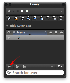
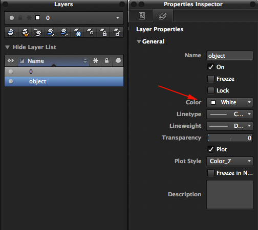
All objects are drawn on a layer. You can group objects on a single layer or create multiple layers in order to better organize your drawing. |
Linetype |
All objects are drawn with a particular linetype. Examples would be solid, center, dashed, etc. |
Object |
Any item that is in the AutoCAD database. Also known as an entity. An AutoCAD drawing file is actually one large database containing all the information needed to reproduce the objects when the file is opened. Information for layers and linetypes, are stored in this manner. |
Origin |
The (0,0) point of your current coordinate system. |
Orthographic mode |
This is a drawing mode that allows you to draw only perpendicular lines. It is toggled on and off by pressing the F8 key. |
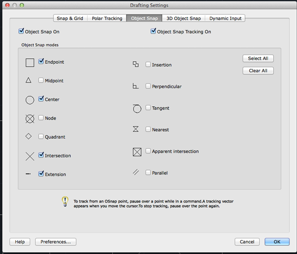
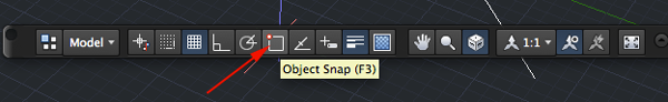
Osnap - Object Snap |
This is a method of 'snapping' to certain, precise points
on an object. |
Pan |
To move around the drawing by dragging the drawing area around your screen. |
Panel |
A grouping of commands on the ribbon. The Ribbon runs across the top of the drawing space and contains panels - each panel has a group of associated tools. Switch to different panels by clicking on the tabs at the top of the ribbon. (PC only). |
Selection set |
The current group of objects selected for modifying. |
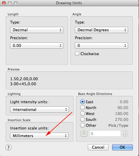
Units |
The basic drawing unit set for your drawing. You can use inches or millimeters depending on your needs, but if you are modeling for Desktop 3D priting you should only use millimeters. You can also set the precision that you want displayed. |
View |
A particular area of your drawing. |
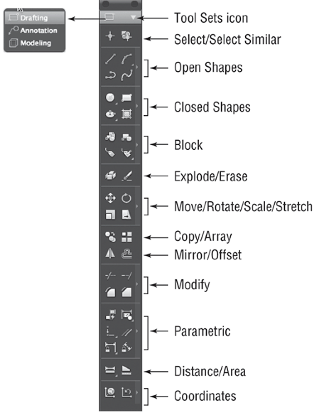
AutoCAD does have a tool palette, but you will find that with practice using just the command line will allow you to work much faster.
 .
.


 .
.
 .
.
