OpenSCAD Introduction
What is it?
OpenSCAD is software for creating solid 3D CAD objects. It is free software and available at openscad.orgfor Linux/UNIX, MS Windows and Mac OS X. Make sure to download the latest Development Snapshot.OpenSCAD focuses on the CAD aspects of 3D modeling and is good for creating 3D models of machine parts or any part where you want to specify parameters.
OpenSCAD is not an interactive modeller. Instead it reads in statements that describes the object and it renders the 3D model from that code. This gives you full control over the modeling process and enables you to easily change any step in the process or to make designs that are defined by configurable parameters.
OpenSCAD provides two main modelling techniques:
- Constructive Solid Geometry
- Extrusion of 2D outlines
Click here for the official User Manual
Basics
- If you do not have OpenSCAD installed yet, download the latest Development Snapshot from openscad.org
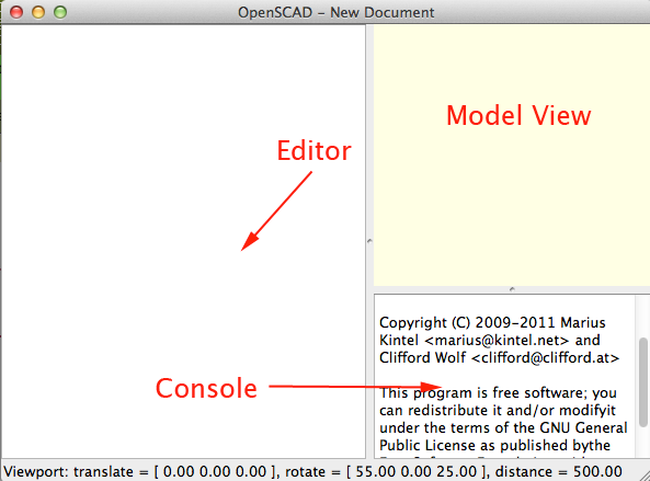
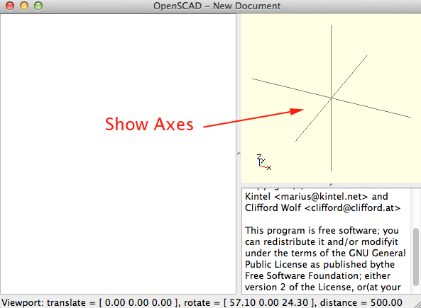
- When you open OpenSCAD you will see the interface:
- To display the axes in the model view press Command+2 (MAC) or CTRL+2 (Windows and Linux).
- Statements in OpenSCAD end with a semi-colon.
cube([10,10,20]);
- OpenSCAD does not automatically indent your code, but you are encouraged to use indents for readability
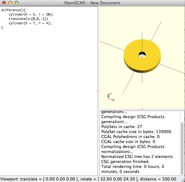
difference(){ cylinder(h = 5, r = 20); translate(v=[0,0,-1]) cylinder(h = 7, r = 4); } - To comment out a single line begin the comment with a double-slash (//)
//this is a comment

myVar=10;//this is also a single-line comment
- To comment out multiple lines, begin the comment with slash-star and end the comment with star-slash:
/* This is a multi-line comment.
I started the comment on the line above.
I will complete the comment on the line below.
*/
- Press F5 to render. This will show you what your model looks like in the model view
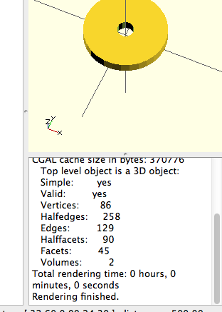
- Press F6 to compile and render. This will create a model that is ready to export as an stl file:
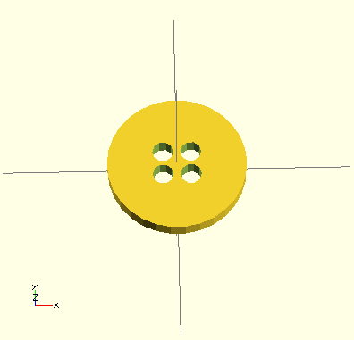
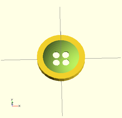
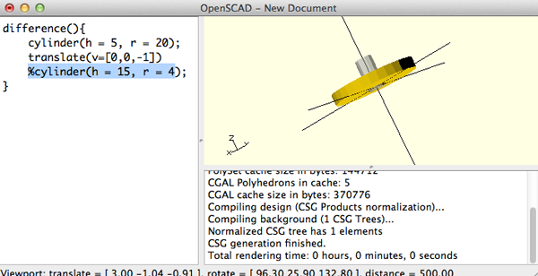
- You can use %(the Background Modifier) to ignore the subtree for the normal rendering process and draw it in transparent gray. In other words to ghost an object. This is handy when you want to see what is being differenced:
- There is also * (the Disable Modifier), which will ignore the entire subtree.
difference() {
        cylinder (h = 4, r=1, center = true, $fn=100);
        *rotate ([90,0,0]) cylinder (h = 4, r=0.9, center = true, $fn=100);
}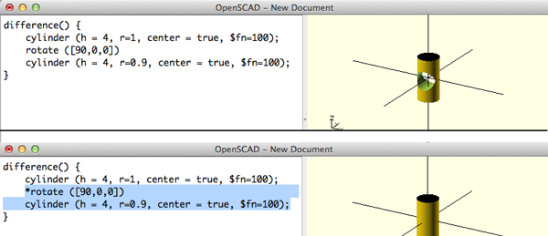
- $fn sets the resolution. This can be at the top of your file.
Here is how to set the resolution to 128.$fn=128;
- You can move the rendered object by:
-
Dragging with left mouse button to rotate the view. You can see the rotate values at the bottom of the window.
- Also try dragging with the left mouse while holding down the SHIFT key.
- Dragging with the right mouse button to translate (move) the view. You can see the translate values in the bottom of the window.
- Also try dragging north and south with the right mouse while holding down the SHIFT key.
- Using the mouse scroll to zoom in and out. The Viewport line at the bottom of the window will show a change in the distance value.
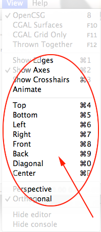
- Use the following quick key combinations to control the view:
-
Dragging with left mouse button to rotate the view. You can see the rotate values at the bottom of the window.
- Statements in OpenSCAD end with a semi-colon.
View Options
Show Edges (CTRL/⌘+1)
If Show Edges is enabled, both OpenCSG and CGAL mode will render edges as well as faces, CGAL will even show vertices. In CGAL grid mode, this option has no effect.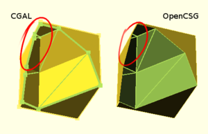
Enabling this option shows the difference between OpenCSG and CGAL quite clearly: While in CGAL mode you see an edge drawn everywhere it belongs, OpenCSG will not show edges resulting from boolean operations – this is because they were never explicitly calculated but are just where one object's Z clipping begins or ends.
Show Axes (CTRL/⌘+2)
If Show Axes is enabled, the origin of the global coordinate system will be indicated by an orthogonal axes indicator. Additionally, a smaller axes indicator with axes names will be shown in the lower left corner of the viewing area. The smaller axes indicator is marked x, y, z and coloured red, green, blue respectively.Show Crosshairs (CTRL/⌘+3)
If Show Crosshairs is enabled, the center of the viewport will be indicated by four lines pointing in the room diagonal directions of the global coordinate system. This is useful when aligning the viewing area to a particular point in the model to keep it centered on screen during rotation.Animation
The Animate option adds an animation bar to the lower edge of the screen. As soon as FPS and Steps are set (reasonable values to begin with are 10 and 100, respectively), the current Time is incremented by 1/Steps, FPS times per second, until it reaches 1, when it wraps back to 0.Every time Time is changed, the program is re-evaluated with the variable $t set to the current time.
To see how animate works, download spiderbot and run the main.scad files
Primitives
cube
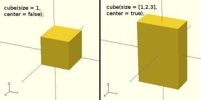
Creates a cube at the origin of the coordinate system. When center is true the cube will be centered on the origin, otherwise it is created in the first octant. The argument names are optional if the arguments are given in the same order as specified in the parametersCube Parameters
sizeSize can be a decimal or a 3 value array. If a single number is given, the result will be a cube with sides of that length. If a 3 value array is given, then the values will correspond to the lengths of the X, Y, and Z sides. Default value is 1.
center
This is a Boolean, so it either set to true or false. This property determines the positioning of the object. If set to true, the object is centered at (0,0,0). Otherwise, the the object is placed in the positive quadrant with one corner at (0,0,0). The default is set to false. Usage examples:
cube(size = 1, center = false);
cube(size = [1,2,3], center = true);
sphere
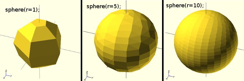
Creates a sphere at the origin of the coordinate system. The argument name is optional.Sphere Parameters
rr is a decimal. This is the radius of the sphere. The resolution of the sphere will be based on the size of the sphere and the $fa, $fs and $fn variables. Usage examples:
sphere(r = 1);
sphere(r = 5);
sphere(r = 10);
sphere(2, $fn=100); // this will create a high resolution sphere with a 2mm radius
sphere(2, $fa=5, $fs=0.1); // will also create a 2mm high resolution sphere but this one does not have as many small triangles on the poles of the sphere
cyclinder
Creates a cylinder at the origin of the coordinate system. When both radii are same it is also possible to specify a single radius using the argument name r. The argument names are optional if the arguments are given in the same order as specified above.Cylinder Parameters
hh is a decimal. This is the height of the cylinder. Default value is 1.
r1
r1 is a decimal. This is the radius of the cylinder/cone on bottom end. Default value is 1.
r2
r2 is a decimal. This is the radius of the cylinder/cone on top end. Default value is 1.
r
Decimal. The radius of both top and bottom ends of the cylinder. Use this parameter if you want a non-cone shaped cylinder. Default value is 1.
$fa
$fa is angle in degrees
$fs
$fs is angle in mm Usage examples:
cylinder(h = 10, r1 = 10, r2 = 20, center = false);
cylinder(h = 10, r1 = 20, r2 = 10, center = true);
cylinder(h = 10, r=20);
cylinder(h = 10, r=20, $fs=6);

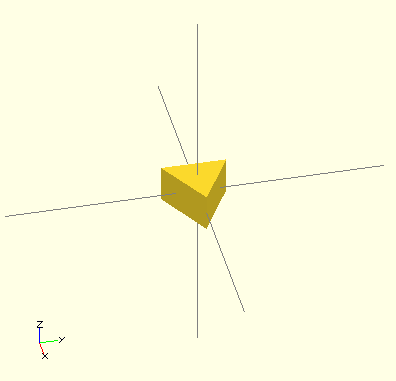
Helpful Tip: The $fn parameter dictates how many facets the circumference of your cylinder will have. A cylinder with 8 facets will look like an octagon and a cylinder with 128 facets would probably look almost perfectly circular. You can make triangles by creating cylinders with $fn=3 or just three facets. This is a quick and simple way to get an equilateral triangle.
cylinder(h=10,r=10,$fn=3, center=true);
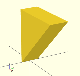
polyhedron
Creates a cylinder at the origin of the coordinate system. When both radii are same it is also possible to specify a single radius using the argument name r. The argument names are optional if the arguments are given in the same order as specified above. Usage examples:polyhedron(points = [ [x, y, z], ... ], triangles = [ [p1, p2, p3..], ... ], convexity = N); polyhedron(points=[[0,0,0],[100,0,0],[0,100,0],[0,100,100]], triangles=[[0,1,2],[1,0,3],[0,2,3],[2,1,3]]); polyhedron ( points = [[0, -10, 60], [0, 10, 60], [0, 10, 0], [0, -10, 0], [60, -10, 60], [60, 10, 60]], triangles = [[0,3,2], [0,2,1], [3,0,4], [1,2,5], [0,5,4], [0,1,5], [5,2,4], [4,2,3], ]);
Your First Model
- Open OpenSCAD.
- Type the following into the editor window:
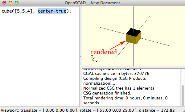
cube([5,5,4]);
- Make sure that when you render, you see the axes. If you do not see them, turn on Show Axes under the View Menu or press Command+2 (MAC) or CTRL+2 (Windows and Linux).
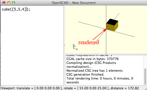
- You should notice that the object is rendered in the first quadrant. By adding center=true to the first statement, you can center the cube on the axes lines:
- To create another cube, you could copy and paste the line of code. You won't see the second cube.
Why not?
You won't see the second cube because both cubes are occupying the same space.
To move the second cube away, you have to call translate().
This line is a bit weird because it doesn't end in a semi-colon.
Why not?
It doesn't have a semi-colon because the translate() call is part of the cube statement:cube([5,5,4]); translate([6,0,0]) cube([5,5,4], center=true);
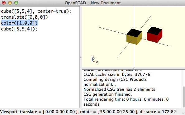
- color() like translate()
is part of the object statement.
Here is how you would make the second object red:cube([5,5,4]); translate([6,0,0]) color([1,0,0]) cube([5,5,4]);
While the color of your model in OpenSCAD does not determine how your model will print, it is nice to be able to control the colors. To change the color use the following syntax:or//using color names color("name_of_color_from_list_below") cube([5,5,4], center=true);A chart of the color names is as follows://using RGB values from 0-1.0 color([1,0,0]) cube([5,5,4]);
Purples Lavender Thistle Plum Violet Orchid Fuchsia Magenta MediumOrchid MediumPurple BlueViolet DarkViolet DarkOrchid DarkMagenta Purple Indigo DarkSlateBlue SlateBlue MediumSlateBlue Pinks Pink LightPink HotPink DeepPink MediumVioletRed PaleVioletRed Blues Aqua Cyan LightCyan PaleTurquoise Aquamarine Turquoise MediumTurquoise DarkTurquoise CadetBlue SteelBlue LightSteelBlue PowderBlue LightBlue SkyBlue LightSkyBlue DeepSkyBlue DodgerBlue CornflowerBlue RoyalBlue Blue MediumBlue DarkBlue Navy MidnightBlue Reds IndianRed LightCoral Salmon DarkSalmon LightSalmon Red Crimson FireBrick DarkRed Greens GreenYellow Chartreuse LawnGreen Lime LimeGreen PaleGreen LightGreen MediumSpringGreen SpringGreen MediumSeaGreen SeaGreen ForestGreen Green DarkGreen YellowGreen OliveDrab Olive DarkOliveGreen MediumAquamarine DarkSeaGreen LightSeaGreen DarkCyan Teal Oranges LightSalmon Coral Tomato OrangeRed DarkOrange Orange Yellows Gold Yellow LightYellow LemonChiffon LightGoldenrodYellow PapayaWhip Moccasin PeachPuff PaleGoldenrod Khaki DarkKhaki Browns Cornsilk BlanchedAlmond Bisque NavajoWhite Wheat BurlyWood Tan RosyBrown SandyBrown Goldenrod DarkGoldenrod Peru Chocolate SaddleBrown Sienna Brown Maroon Whites White Snow Honeydew MintCream Azure AliceBlue GhostWhite WhiteSmoke Seashell Beige OldLace FloralWhite Ivory AntiqueWhite Linen LavenderBlush MistyRose Grays Gainsboro LightGrey Silver DarkGray Gray DimGray LightSlateGray SlateGray DarkSlateGray Black - Replace the cubes with the following lines of code and render:
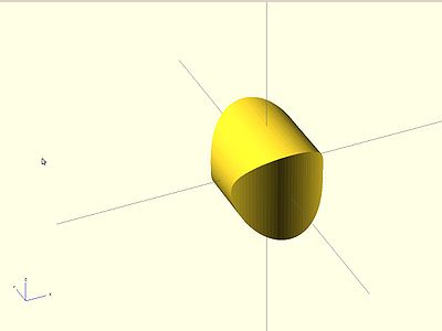
union(){
    difference() {
      cube(30, center=true);
      sphere(20, $fn=100);
     }
     translate([0, 0, -15])
     cylinder(h=40, r=13.5);
}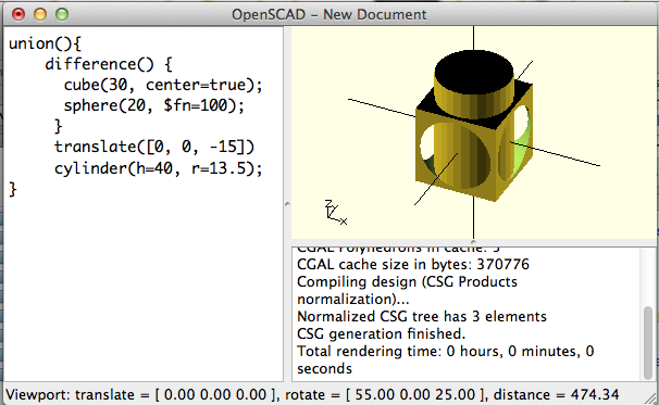
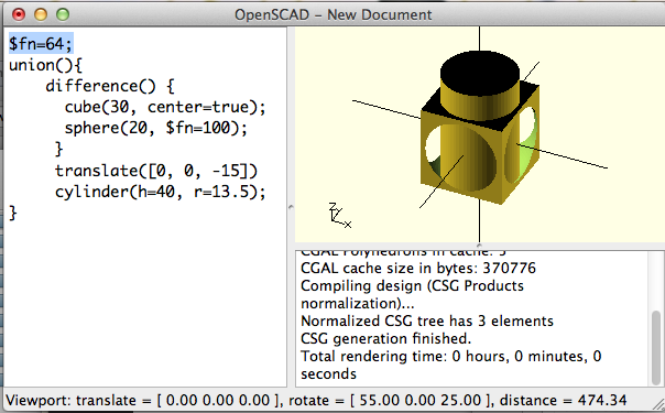
- Now add this line to the very beginning:
And re-render:
$fn=64;
union(), difference() and intersection() are examples of boolean operations
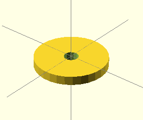
union() creates a union of all the child nodes.union() { cylinder (h = 4, r=1, center = true, $fn=100); rotate ([90,0,0]) cylinder (h = 4, r=0.9, center = true, $fn=100); }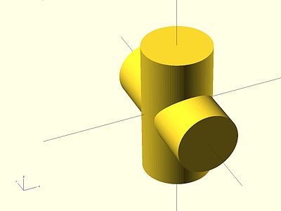
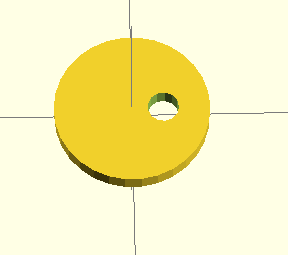
difference() subtracts the second (and all further) child nodes from the first.difference() { cylinder (h = 4, r=1, center = true, $fn=100); rotate ([90,0,0]) cylinder (h = 4, r=0.9, center = true, $fn=100); }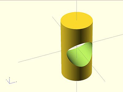
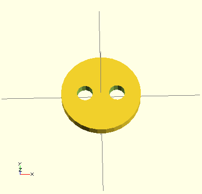
intersection() creates the intersection of all child nodes and keeps the overlapping portion:intersection() { cylinder (h = 4, r=1, center = true, $fn=100); rotate ([90,0,0]) cylinder (h = 4, r=0.9, center = true, $fn=100); }