LED Basics
 © Royalty Free/Corbis
Microcontrollers
Microcontrollers can be thought of
as very small, inexpensive computers which may be programmed to control systems
such as cell phones, microwave ovens, toys, automotive systems, etc. by sensing input from the
real world and controlling those devices based on that input.
Most electronic devices you use today have a microcontroller in them of some form or another.
A typical household has upwards of 25 to 50 microcontrollers performing
embedded control
in numerous appliances and devices.
Microcontrollers are easy to use with simple sensors and output devices,
and they can communicate with desktop computers fairly simply as well.
They're very useful for when you're designing a simple interactive device that doesn't need the
full power of a desktop computer, but does need to be smaller or cheaper.
How it works
A program is written in the
Arduino, a special program running on your computer
that allows you to write programs for the Arduino board in a simple language modeled
after the
Processing language. When you press the button that uploads
the program to the board: the code you have written is translated into
C, and is passed on to the
avr-gcc compiler,
a piece of open-source software that translates the code into the
language the microcontroller can understand.
This last step is quite important because it's where Arduino is making your life simple
and hiding away as much as possible of the complexities of programming microcontrollers.
The Interface:
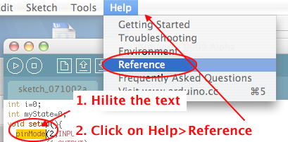
If you need Help with you program...
Hilite a command and then click on
Help menu and select
Reference:
Common functions
-
pinMode()—set a pin as input or output
- digitalWrite()—set a digital pin high/low
- digitalRead()—read a digital pin's state
- analogRead()—read an analog pin
- analogWrite()—write an "analog" value
- delay()—wait an amount of time
- millis()—get the current time
Arduino Programming Notebook
Basic Sketch Structure
- Declare variables at top
- Initialize values
-
setup()— run once at beginning, set pins
- Running
- loop()— run repeatedly, after setup()
Read the following:
There are 12 digital I/O (Input/Output) pins on the Arduino chip. These are the pins through which input and output devices may be connected.
Depending on the code that is written, each pin may act as an input to read a device, or as an output to control a device.
You will begin by using a very common and simple output device, the LED:
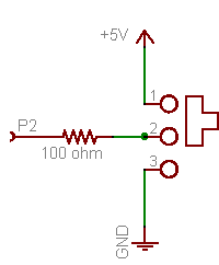
Using an Active High LED, connect pin 8 to a 220 resistor, which connects to one side of an LED and connect the other side of the LED to ground:

An LED is a diode, meaning electrons can flow in
only one direction. In other words, polarity is important. The LED should have a
flat side indicating the cathode or negative terminal.
Also, the anode (positive terminal) generally has a
longer lead than the cathode.

|
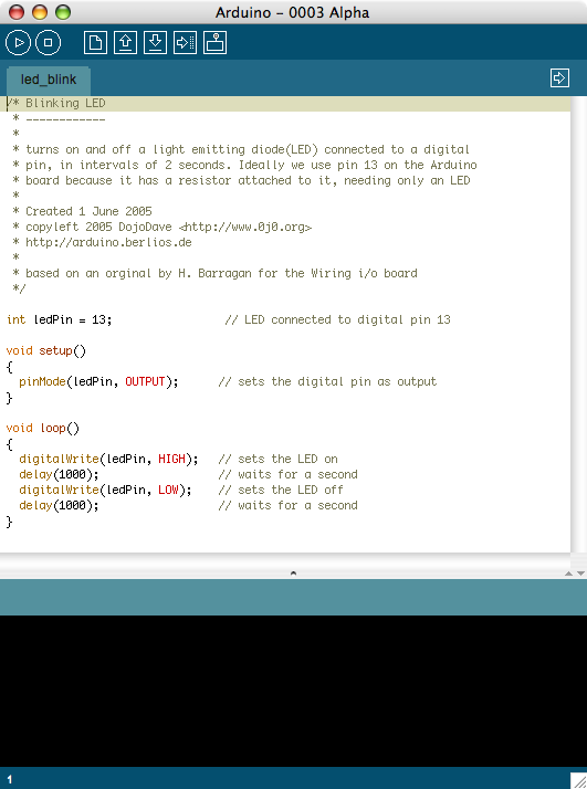
Here is the code to light the LED:
/* blink an LED*/

int LED1=8;

void setup(){

    pinMode(LED1,OUTPUT);

}

void loop(){
    digitalWrite(LED1,HIGH);
    delay(500);
    digitalWrite(LED1,LOW);
    delay(500);
}
| Code |
Explanation |
| /* */ |
A comment |
| digitalWrite(8,HIGH) |
defines the pin to be an output and sets it to a HIGH state, digital 1 or 5V |
| digitalWrite(8,Low) |
defines the pin to be an output and sets it to a LOW state, digital 0 or 0V |
| delay(500) |
instructs the chip to wait for the defined number of milliseconds (1/1000 seconds). |
Modify the code so that the light is on for 50 milliseconds and off for 50 milliseconds. Before you run it,
what do you think will happen?
/ / Button Basics
Pull-ups and Pull-downs
A switch that alternates connections, like this one, diagrammed here
is suprisingly complex and 10 times more expensive than a little tactile button.
To get your button to act this way, use a trick called a
pull-down resistor:
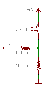
The pull-down resistor here is the 10K resistor.
When the switch is held down, the 100Ω resistor is
connected directly to 5V. When the switch is released,
the 100Ω resistor is connected to the 10K resistor
which pulls it down to ground.
Think of it this way:
When you press the button and connect the 100Ω resistor to 5V,
the button has a very small resistance (less than 1 Ω),
so it provides a strong pull to 5V.
The 10KΩ resistor is also connecting the 100Ω
resistor to ground, but since the 10KΩ resistor has 10000 times
more resistance than the button, its a very weak pull
to ground and can't compete.
The strong 5V connection overpowers the weak ground
connection and the input pin reads HIGH.
However, when the switch is disconnected, there is no longer a strong pull to 5V. In fact, its let go completely. But there is still weak pull to ground. Despite being a weak connection, it's better than nothing and so the resistor pulls the input pin to LOW.
Keeping it on
Turning on and off an LED when a button is pressed is lovely, but think about switches you live with. If you turn on the TV, you don't want to hold the button to keep it on. What you need is an alternating action switch where the press-and-release of a button does something, not just press-and-hold. Basically you want to test if the button was just released, or just pressed.
To do this, you need to keep track of the button input value, to see if it's changed. This is called the
state of a button. When the state changes (an action occurs), that's when you want to perform an action.
You'll also need a flag to keep track whether the light is on or off.
Wire up your board, modify the code and upload it to the chip:
int led=8;
int btn = 7;              // switch is connected to pin 2
int val;                        // variable for reading the pin status
int btnState;                // variable to hold the last button state
boolean lightOn=false;


void setup() {
  pinMode( led, OUTPUT);    // Set the switch pin as input
  pinMode( btn, INPUT);    // Set the switch pin as input
  btnState = digitalRead(btn);   // read the initial state
}


void loop(){
  val = digitalRead( btn);      // read input value and store it in val

  if (val != btnState) {          // the button state has changed!
    if (val == HIGH) {                // check if the button is pressed
      lightOn=!lightOn;
    }
  }
  //control the light here


  btnState = val;                 // save the new state in our variable
}
/ /Shooting Star
Connect 11 LEDs to 11 arduino digital pins through 220 Ohm resistors.
The program should light up LEDs until it reaches the number of LEDs equal to the size you have established for the tail.
Then it will continue lighting LEDs towards the left to make the line keep moving,
and will start erasing from the right, to make sure you see the tail (otherwise you would just light up the whole line of leds.
This will happen also if the tail size is equal to or bigger than 11).
The tail size should be relatively small in comparison with the number of LEDs in order to see it.
Copy, paste and complete the following:
// Variable declaration
  int pinArray [] = { ________}; // Array of LED pins
  int timer = 100;    // delay
  int tailLength = 4; // Num of LEDs that stay lit before you start turning them off
  int lineSize = 11;  // Number of LEDs connected

  void setup(){
  //turn all your leds to OUTPUTS
  for(int i=__; i<___;i++){
   pinMode(i,______);
  }

  }
  // Main loop
  void loop(){

    int tailCounter = tailLength;   // set up the tail length in a counter
    for (int i=__; i<_____; i++){
    // light up  the LEDs consecutively
     __________________________
   // Add a delay. This time variable controls how fast you light them up
    delay(____);
     if (tailCounter == 0){

     // turn off the LEDs depending on  tailLength
        digitalWrite(pinArray[i-tailLength],________);

      }else if (tailCounter > 0)
         tailCounter--;
   }
    for (int i=____; i<______; i++){

    // turn off the LEDs
     digitalWrite(________ , ________);
     //pause
     ________
   }
}
Combine the code above with your toggle switch.