Introduction
The
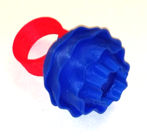
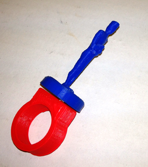
Ring-A-Thing is a modular ring-building kit that allows you to press-fit a small cube magnet into the base and top parts of your ring, enabling you to switch out designs on your printed ring. Be a new superhero every day, change your ring with your mood or the season, etc.
This project is a derivative of
IWorkInPixel's Ring-a-Thing TBuser's Ring-A-Thing w/ Pin Connectors Cymon's TARDIS Ring-a-Thing
You will need a minimum of two 1/8 inch cube
neodymium magnets per ring
OpenSCAD
OpenSCAD is software for creating solid 3D CAD objects. It is free software and available for Linux/UNIX, MS Windows and Mac OS X.
OpenSCAD is good for creating 3D models of machine parts or any part where you want to specify parameters.
OpenSCAD is not an interactive modeller. Instead it reads in statements that describes the object and then it renders the 3D model from that code. This gives you full control over the modelling process and enables you to easily change any step in the process or make designs that are defined by configurable parameters.
OpenSCAD provides two main modelling techniques:
- Constructive Solid Geometry
- Extrusion of 2D outlines
Numbers in OpenSCAD are in millimeters. So
circle(5); or
circle(r=5); draws a circle with a radius of 5mm.
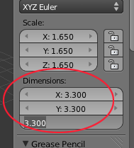
Here is the code for the base of the ring. Measure the diameter of your finger at the largest part and pass in that value. If you want a delicate ring, the second parameter should be set to true.
$fn=100;
magnet=3.4;
ring_size = 18;
rotate([0,0,90])
ring(ring_size, true);

module ring(size, d=true) {
    difference() {
            union() {
              cylinder(r=size/2+2, h=9, center=false);
              translate([0, size/4+2.5, 9/2])
            if(d){
                  cube(size=[size, size/2+4, 9], center=true);
            }else{
                  cube(size=[size+4, size/2+4, 9], center=true);
                }
            }
            translate([0, 0, -1])
        cylinder(r=size/2, h=12+2, center=false);

        translate([-1.5, size/2+1.5,2.5])
        cube(magnet);
     }
}
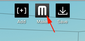
When you have configured your ring press
F5 to compile the image. If everything looks good, press
F6 to compile and render—build the mesh.
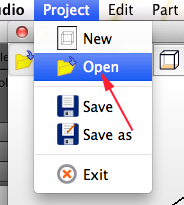
After your mesh is created select
Export as STL from the
Design menu.
STL or
STereoLithography files describe the surface geometry of a 3D object and are used to build physical 3D CAD Models.
stl files are created using a mesh made of triangles that represents the physical part of your object. The STL file is a complete listing of the xyz coordinates of the vertices and normals, the vectors perpendicular to a surface that determine the orientation for the triangles, that describe the 3D object.
A good STL file size is between .5MB for a simple file to 10MB for a large complicated one. Generally, if your part is outside of these parameters, you'll need to resize it. A good STL file must also conform to two rules.
-
Adjacent triangles must have two vertices in common
- The orientation of the triangles (what side of the triangle is in and what side is out) as specified by the vertices and normals must agree
Minor gaps and inconsistencies can usually be fixed by specialized STL-handling software. If you have more significant problems, you'll have to go back to your original CAD model.
An STL file can be termed bad because of translation issues. In many CAD systems, the number of triangles that represent the model can be defined by the user. If you are using too many triangles, the stl file size can become unmanageable. If you're using too few triangles to describe your object, your curved areas will not be properly defined and your cylinders might look like hexagons.
Thingiverse
Thingiverse is a universe of things.
It is also a place to share your digital designs with the world, as well as a community of people who create and share designs freely, so that all can benefit from them.
To save your own digital designs, you need to register at Thingiverse. All the information that is required is a username, email, password and human status.
Once you've registered, you can choose to fill out your profile or not.
By hitting the Email Tab, you can request emails
- Whenever someone posts a new comment on something you've designed.
-
Whenever someone posts a new comment on something you've made.
-
Whenever someone creates a derivative from of one of your things.
-
Whenever someone physically makes of one of your things.
-
Whenever one of your things has been featured.
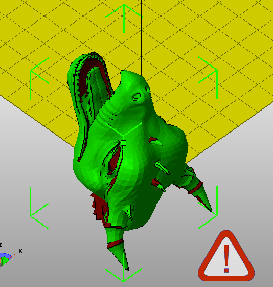
Sometimes there are problems with downloaded files. The creator may have made the model for animation and not 3D printing or the creator may have not realized there were issues with the file. You can fix these files either using Netfabb or Meshmixer.
Netfabb
- Open Netfabb
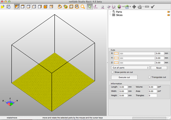
- Open the STL
- If you have errors you will see an exclamation mark in a triangle
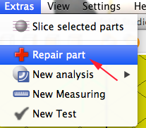
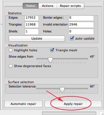
- To repair the problems click on Repair Part from the Extras menu
- Select Automatic Repair
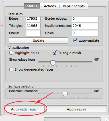
- Execute the repair:
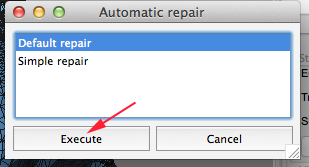
- Now Apply the repair
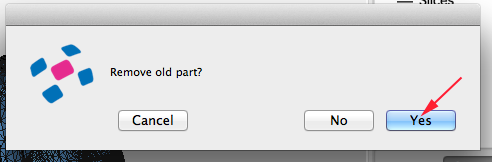
- Confirm that you want to remove the old part
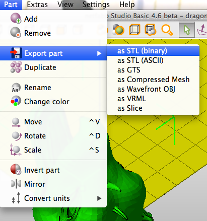
- Export the fixed STL file y clicking on Part>Export>STL (binary)
Meshmixer
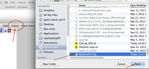
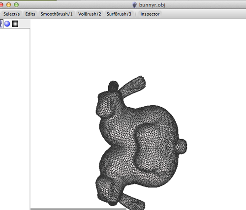
- Open meshmixer.
- Click Import to open your stl.
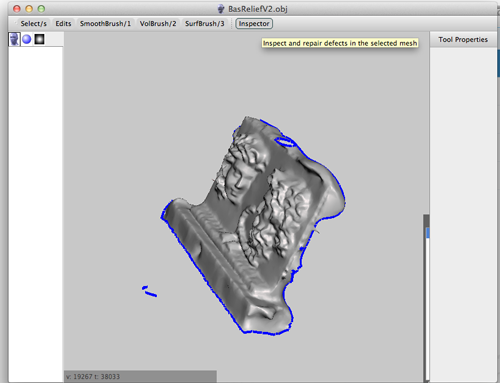
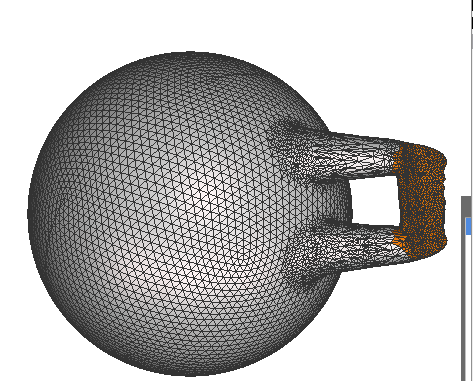
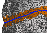
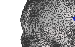
- Click Inspector.You'll see your model with a number of spheres attached to it.
Blue spheres represent holes
Red spheres represent non-manifold areas
Magenta spheres represent disconnected components
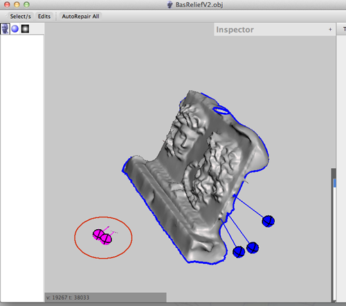
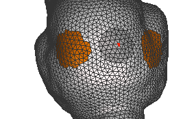
- Left clicking on a sphere will repair the problem.
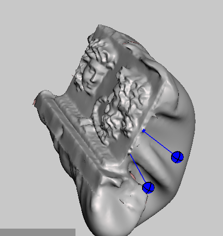
- Right clicking on the sphere will select the area and allow you to edit that part of the mesh.
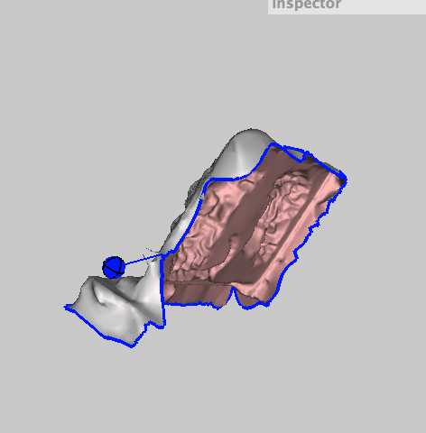
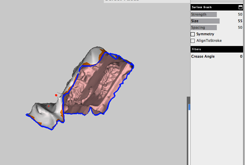
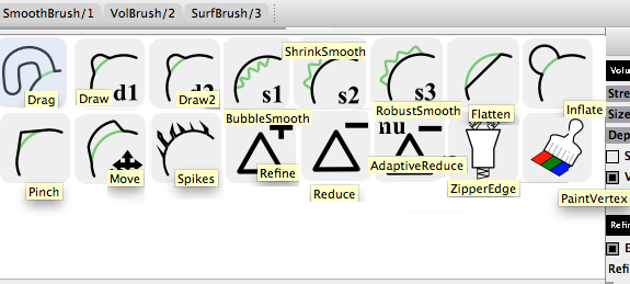
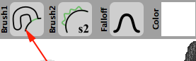
- You can use the volumetric brushes to make changes to the model:
Volumetric Bushes
To select The Secondary brush hold down SHIFT and LeftMouse drag.
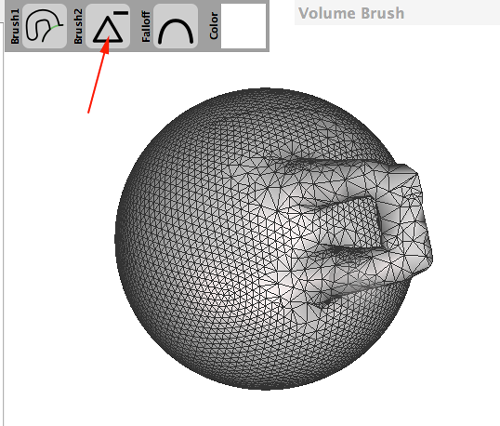
To reduce the number of triangles in the mesh:
- Select Drag
- Increase the strength of the brush
- Select Reduce and paint over the mesh
- You can also use the Edit tool:
Mirror
- Select how much of the model you want to mirror by adjusting the plane
- Accept the transformation
Duplicate:
- Select Duplicate
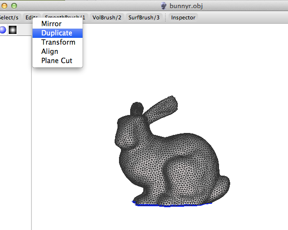
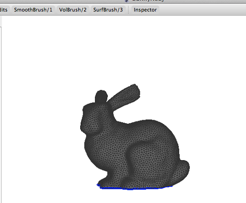
- Select Transform and move the duplicate
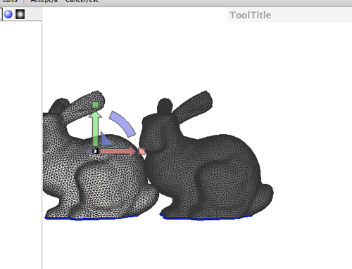
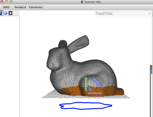
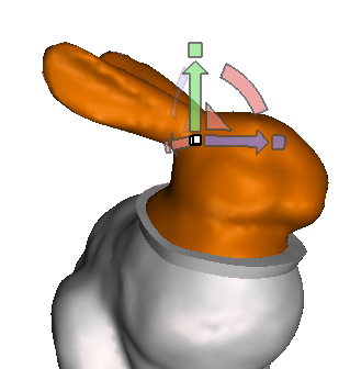
Transform:
- Select Transform
- Make adjustments (scale, move, rotate)
- Accept transformation (A)
- Repeat steps 2 and 3 until you get the necessary form.
Align allows you to change the alignment.
Plane Cut allows you to cut off and make a mesh solid by adjusting and accepting the transformation.
- You also have functions at your disposal:
Functions
Once you've made a selection there are a few things you can do:
- Erase and Fill (F). Allows you to select an area around a hole and fill it, or remesh a selected mesh.
- Discard (X). Allows you to make a selection and discard it.
- Reduce. Allows you to select the mesh and reduce the triangles.
- Remesh. Allows you to remesh a selected area.
- Extrude. Allows you extrude an area by dragging the offset selector.
- Extract. Allows you to make a separated copy of your selection
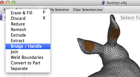
- Bridge/Handle. Allows you to create support or connect two areas by making a selection of the areas.
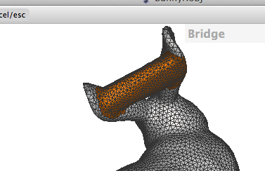
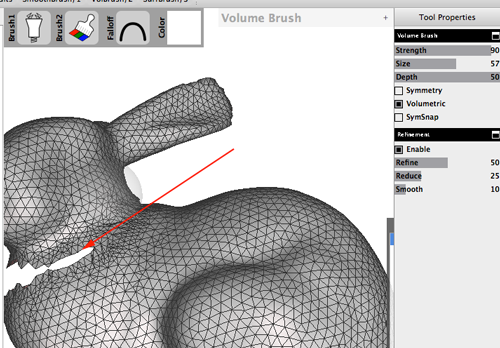
Then reduce the triangles using the the Volumetric Brush:
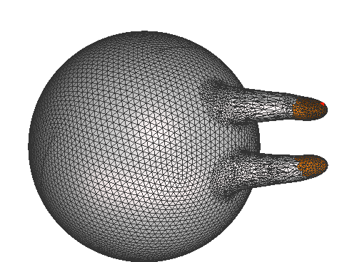
This tool also allows you to make a hole:

- Join.
- Weld Boundaries. Use this tool after you have used the zipper brush.
Make a selection of the area zippered, then weld the seem together. Follow this step up with the Smooth Brush.
- Convert to part
- Separate. You use this when you want to combine two meshes.
- When you're done, you can export your file as an STL.


 . Select