Modifying
You shared your first drawings with the guard, but all he has for you are more questions. Like what happens if you didn't use OSNAPS and your lines are too short or too long? Do you have to start over if you make a mistake? Are there easier ways to draw boxes? If I want several boxes do I have to draw each one? What do I do if something is in the wrong place?
Oh, my! There is quite a bit you don't know, but the guard doesn't need to know that. You need to figure this out, and you need to do it quick. The guard wants answers by the end of the day.
- Launch AutoCAD, create a new drawing using the acad.dwt template. Set up your drawing (UNITS, layers).
- Turn on your ENDPOINT Osnap.
- Draw a rectangle 2 units wide by 3 units high using the RECTANGLE command. When you see the prompt to specify the first corner, set it (the bottom left corner) to (0,0). When you see the second prompt use relative coordinates and pass in the appropriate values.
- What you need to do now is move the small rectangle to the right 1 unit and up 1 unit.
To do this, start the MOVE command by typing either M or MOVE and pressing <RETURN>. - Select all the lines of the rectangle. Remember dragging right to left (←) selects everything that touches the selection, dragging left to right (→) must include all segments you want to select. A rectangle is different than four connected segments. All you have to do to select it is click one line.
Press <RETURN> after selecting the rectangle. - Now AutoCAD asks for a base point or displacement. You need to provide a reference point for the move. Click on the bottom left corner of the rectangle or type 0,0 and press <RETURN>.
- AutoCAD now wants a second point of displacement. This is how far you want to move it. This is an opportunity to use relative coordinates. In this case, you want to move it 1 unit over and 1 unit up. So type @1,1 and press <RETURN>. The rectangle will move to its new location.
- Now you want to copy this rectangle 3 units over to the right. The copy command is very similar to the move command. (The only difference is that the copy command leaves an original behind.)
Start the COPY command by typing COPY. - You will be asked to select objects. Select the rectangle you just moved.
- AutoCAD now wants the base point or displacement just like in the MOVE command. Select the bottom left corner of the rectangle.
- Once you've done this, you need to tell AutoCAD what the second point of displacement is. Since you want to move the rectangle over 3 units to the right, type in @3,0 and press <RETURN>. The rectangle has now been copied 3 units over.
- You might want to zoom in.
- The first rectangle is not as tall as it should be. Did I change my mind, or am I trying to show you some new tricks? It should be 1 unit taller. To modify the rectangle, use the STRETCH command.
Start the STRETCH command by typing S and pressing <RETURN>:
- AutoCAD now makes you select objects by using a crossing window or crossing polygon (create the selection by dragging a box from the right to left ← over the rectangle). Pressing <RETURN> accepts the selection.

- Pick on the top left corner of the rectangle:
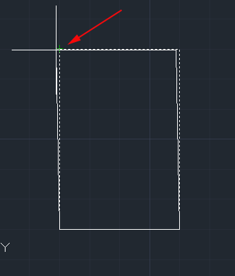
- Now give AutoCAD the second point of displacement. In this case, you want to stretch the rectangle 1 unit up, so type @0,1 and press <RETURN>.
The rectangle is now 1 unit taller.
- Using the Line command and absolute coordinate draw the lines:

- Once the lines are drawn, begin the MIRROR command.
- Select the three lines by clicking on each segment. When they are all selected press <RETURN>:

- You are now asked for the first point of the mirror line. With your endpoint Osnap enabled, or by typing END
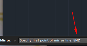
- Click the point (8,2).
- Now select the point on the line at (8,5).

- Once you've clicked on two points, AutoCAD wants to know if you want to delete the old objects. In this case you don't, so accept the default (No) by pressing <RETURN>.

- Draw a line from (2,6) to (2,7.5). Press <RETURN> to end the line.
- Draw another line from (1,7) to (3,7). Press <RETURN> to end the line.
- You should now have two perpendicular lines. What you want to do is trim off the top of the vertical line and create a T.

- Start the TRIM command. It will first ask for a cutting edge (this is what you want to trim to). Select the horizontal line and press <RETURN> .
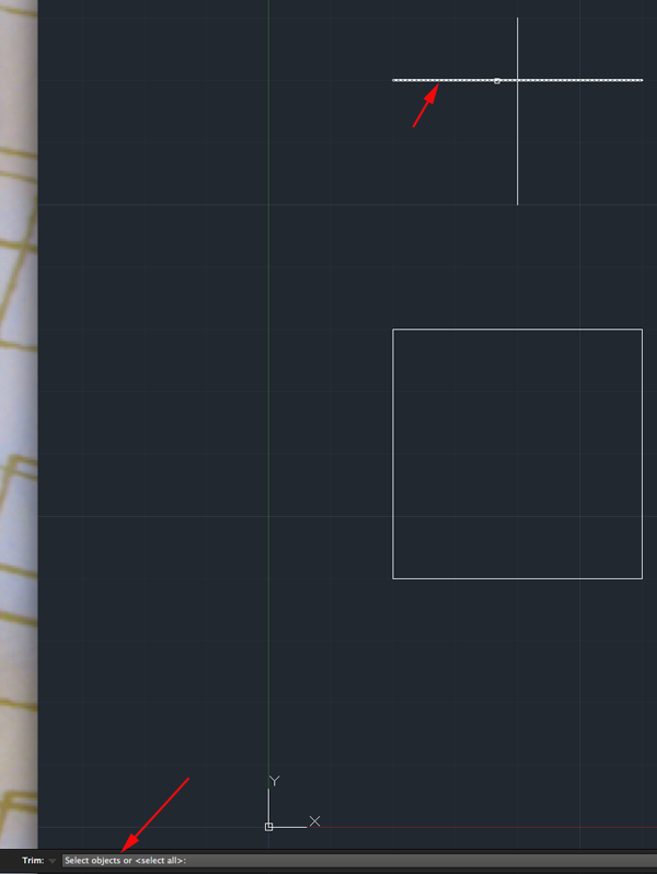
- It will now ask for the object to be trimmed. Select the vertical line anywhere above the horizontal (cutting) line and press <RETURN> to finish the command.
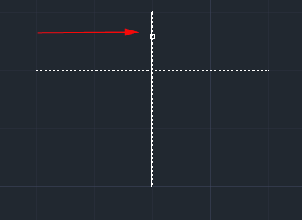

the command line:Command: TR <RETURN> TRIM Current settings: Projection=UCS, Edge=None Select cutting edges ... Select objects: <Select the Horizontal line> 1 found Select objects: <RETURN> Select object to trim or shift-select to extend or [Fence/Crossing/Project/Edge/eRase/Undo]: <Select the vertical line> Select object to trim or shift-select to extend or [Project/Edge/Undo]: <RETURN>
- Draw a LINE from (4,7) to (6,7). Press <RETURN> to end the line.
- Draw another line from (5,5.5) to (5,6.5). Press <RETURN> to end the line.
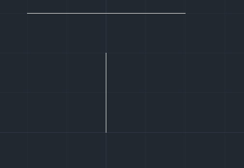
- What you want to do now is extend the vertical line up to the meet the horizontal line. Start the EXTEND command.
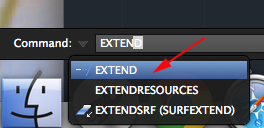
-
AutoCAD asks for a boundary edge (the edge you want to extend to). Select the horizontal line and press <RETURN> .

-
AutoCAD now asks for an object to extend; select somewhere in the top half of the vertical line. Press <RETURN> to end the command.
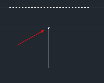
Your command line history should match what is shown below.Command: EX <RETURN> EXTEND Current settings: Projection=UCS, Edge=None Select boundary edges ... Select objects: <Select the horizontal line> 1 found Select objects: <RETURN> Select object to extend or shift-select to trim or [Fence/Crossing/Project/Edge/Undo]: <Select the top half of the vertical line> Select object to extend or shift-select to trim or [Project/Edge/Undo]: <RETURN>

- Draw another rectangle with the bottom left corner at (10,2) and a width and length of 2 units.
- You now need to make a bunch of these boxes. Use the ARRAY command. When prompted select your square and press <RETURN>. Now you have a choice of Arrays. Type r for rectangular. Then at the top of the document specify the columns and rows. Press <RETURN> to accept the array.
- Stretch the top left box of the array 1 unit up.
- Save your drawing.
Source:
Cross, Nigel. Engineering Design Methods. Chichester: Wiley, 1989.
Omura, George; Graham, Richard (Rick) (2010-11-09). Mastering AutoCAD for Mac (Kindle Location 18101). Wiley. Kindle Edition.
Shih, Randy H. AutoCAD 2014 Tutorial Second Level: 3D Modeling. Mission, KS: SDC Publications, 2013. Print.
Shumaker, Terence M., and David A. Madsen. AutoCad and Its Applications: Basics. Tinley Park, IL: Goodheart-Willcox, 2004. Print.
Watson, David. "Learn AutoCAD with Our Free Tutorials." AutoCAD Tutorials, Articles & Forums. N.p., n.d. Web. 05 Jan. 2015.