Solid Modeling
The guard is starting to lose patience with you. "You've spent all your time telling me about lines and 2D shapes. What am I supposed to do with those? I told you I want to design objects!"
You need to calm him down. Explain that there is a method to your madness. Just like you need to walk before you can run, you need to be able to draw 2D shapes before you can consider moving into the next dimension. But you have a deal for him. You can show him right now, today, some quick ways to make 3D forms.
There are three basic types of 3D solids in AutoCAD:
- primitives (BOX, WEDGE, PYRAMID, CYLINDER, CONE, SPHERE, and TORUS)
- composites
- swept objects.
Primitives come right out of the box.
Composite solids are created with Boolean Operations (UNION, SUBTRACT, INTERSECT) or with SOLIDEDIT commands.
Extrusions, revolutions, sweeps and lofts are all considered to be swept solids.
You're going to start with primitives since they are the simplest.
- Launch AutoCad and set up your units and layers.
- In the upper left corner of your document you should see the words Top | 2D Wireframe. When you move your cursor over the words they should change color.
Left click on the word Top and change the view to SE Isometric.

Isometric projection is a method for visually representing three-dimensional objects in two dimensions in technical and engineering drawings. An isometric view of an object occurs when you view the object where the angles between the projections of the x, y, and z axes are all the same, or 120°. - Left click on the words 2D Wireframe and change the selection to Shaded with Edges.

- The default mesh resolution for solid objects in AutoCAD is .5. If you want a higher resolution (this is more appropriate for 3D printing) type FACETRES and set the value to 10.
- Make sure Dynamic Input is disabled.
- Type Box. Specify the first corner at (0,0).
Specify the second corner at (2,2).
Specify the height by typing 2 and pressing <RETURN>. - Type Wedge. Specify the first corner at (4,0).
Specify the length by setting the second corner to (6,4).
Specify the height by typing 2 and pressing <RETURN>. - Type Pyramid.
Type S at the prompt to select Sides.
Type the number of sides you want your base to have.
Type e to select Edge.
Type in (10, 0) when prompted to specify the first endpoint of the edge.
Type in (10, 2) to specify the second endpoint of the edge.
Type 4 as the value for the height. - Type Cylinder.
Specify the center at (12,1).
Type D to select Diameter.
Type 2 to set the diameter.
Type 4 to set the height. - Type Cone.
Specify the center at (15,1).
Type D to select Diameter.
Type 2 to set the diameter.
Type t to specify the radius of the Top edge.
Type 0.5.
Type 4 to set the height. - Type Sphere.
Specify the center at (19,1,2).
Type D to select Diameter.
Type 4 to set the diameter. - Type Torus.
Specify the center at (23,1.5,.5).
Type D to select Diameter.
Type 2 to set the diameter. Type .5 to set the tube radius. -
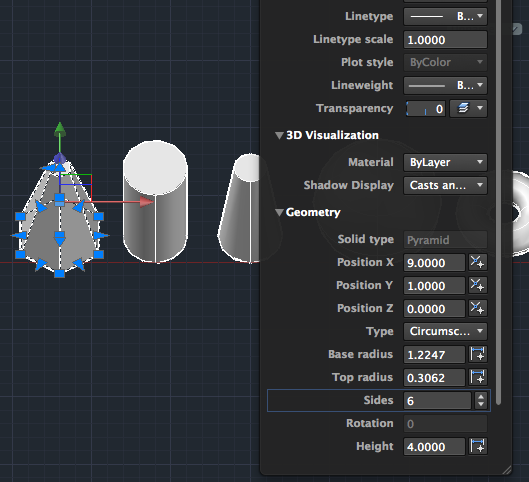
CTRL+clicking on 3D objects brings up a context menu. One of the options available is the Properties.

In the Properties panel you can get information about the Geometry of the object. In this panel you can adjust the position and the dimensions and for 2D shapes and you can see their area. For regions you can see area and perimeter.
In the image below the top radius and sides of the pyramid were changed:
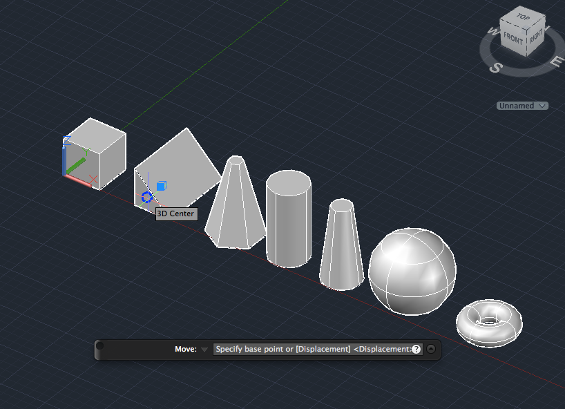
- Your drawing should look similar to this:
- To open the 3D options on the Status Bar click on the arrow on the far right of the bar.
- You can use the subobject selection mode to target specific subobjects.
Enable Face filtering: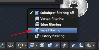 br />
br />
To select a subobject hold the CTRL key and click on the subobject. Once selected you can right click to open the context menu to see the available options. - CTRL click on the front face of the wedge (along the x axis).
- Once selected Right click to bring on the context menu.
- Select Move.
- Specify the 3D center as the first point.
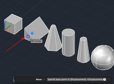
- Type @0,-2,0 for the second displacement point.

- Try modifying another shape.
- The last primitive is called Polysolid.
Type POLYSOLID.
Type w to specify Width.
Type .5 to set width.
Type h to specify Height.
Type 4 to set height.
Enter the coordinate (0,6,0) to select the starting point.
Enter the coordinate (0,10) to specify the next point. Enter the coordinate (25,10) to specify the next point.
Enter the coordinate (25,-5) to specify the next point.
Type a for Arc.
Type c to Close the shape. - Save your work.
A Quest
The guard is a little happier now. But he's still confused about how to make something. Here is your first quest: Use the Polysolid tool to make your initials.Source:
Cross, Nigel. Engineering Design Methods. Chichester: Wiley, 1989.
Omura, George; Graham, Richard (Rick) (2010-11-09). Mastering AutoCAD for Mac (Kindle Location 18101). Wiley. Kindle Edition.
Shih, Randy H. AutoCAD 2014 Tutorial Second Level: 3D Modeling. Mission, KS: SDC Publications, 2013. Print.
Shumaker, Terence M., and David A. Madsen. AutoCad and Its Applications: Basics. Tinley Park, IL: Goodheart-Willcox, 2004. Print.
Watson, David. "Learn AutoCAD with Our Free Tutorials." AutoCAD Tutorials, Articles & Forums. N.p., n.d. Web. 05 Jan. 2015.