Solid Model Editing
"But what if I make a mistake or want to modify a 3D design? Maybe I want to make something hollow. Is there anything that will let me do that?"
What program wouldn't let you modify something? There must be a way to do that. Tell him you'll get back to him in two days with an answer. SOLIDEDIT is a single command in AutoCAD that allows you to edit faces, edges or bodies of solids. This is a great command to invoke to modify your work.
Training
- Launch AutoCAD.
- Create a new drawing and use acad3d.dwt template. Change the units to millimeters and the FACETRES to 10.
- Add a 20x20x20 box:
- Call BOX and press <RETURN>.
- Specify (0,0) as the first point.
-
Specify (20,20) as the second point.
- Set the height to 20.
- Call BOX and press <RETURN>.
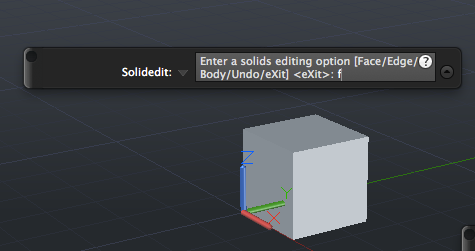
- Call SOLIDEDIT and press <RETURN>.
- Type f for face and press <RETURN>:
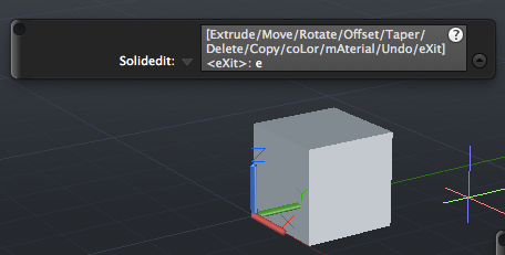
- Type E for Extrude and press <RETURN>
:
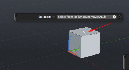
- Select the top face and press <RETURN>:
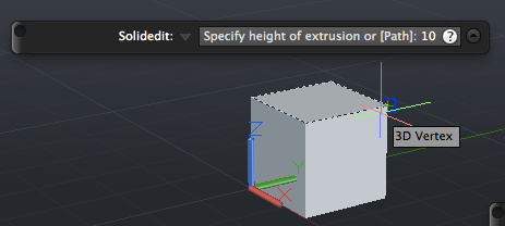
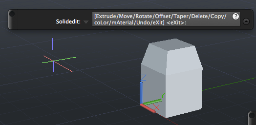
- Specify a height (you can use positive or negative numbers) and press <RETURN>.
This allows you to make your models shorter or taller:
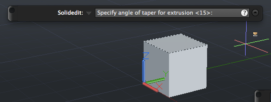
- Specify a taper if desired and press <RETURN>:
- Change the view.
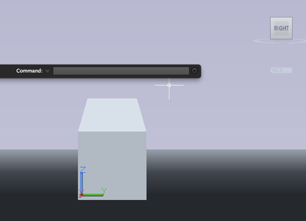
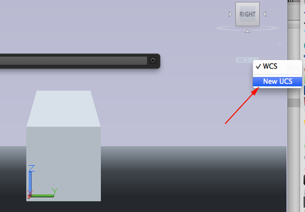
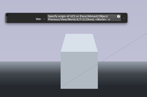
- Create a new UCS and type v so that it will be aligned with the view:
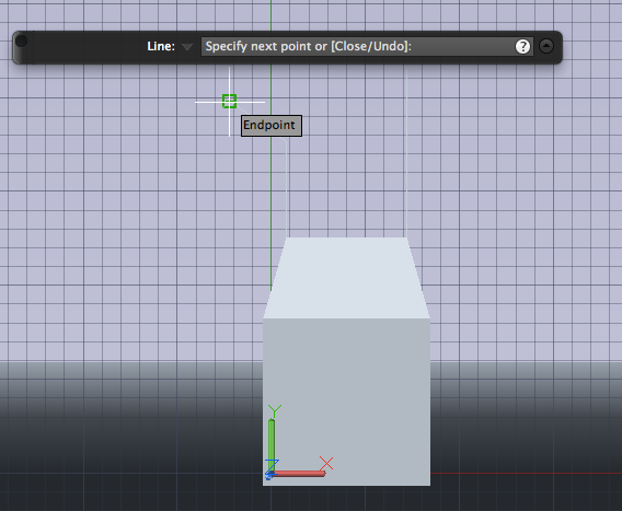
- Draw a spline or a line that will be the path for an extrusion:
- Select WCS and call SOLIDEDIT
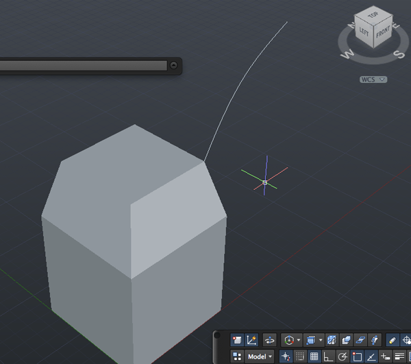
- Select f and press <RETURN>.
Type e and <RETURN>.
Select the top face.
Then select path and press <RETURN>.
Click on the path: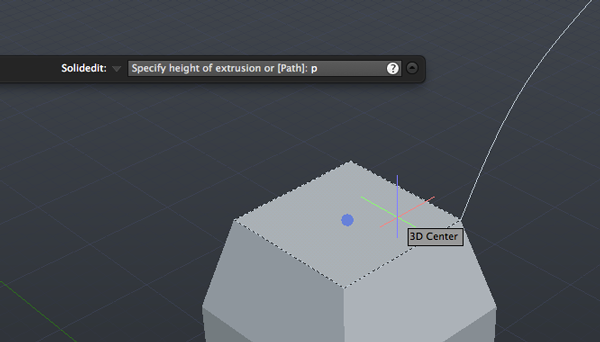
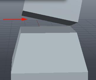
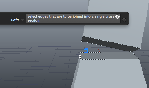
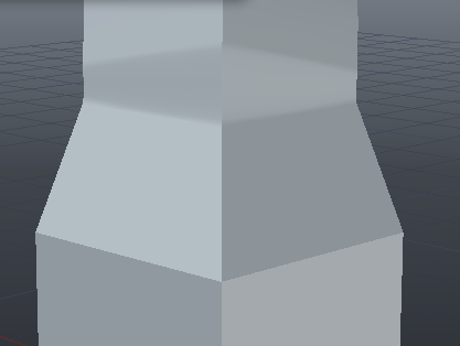
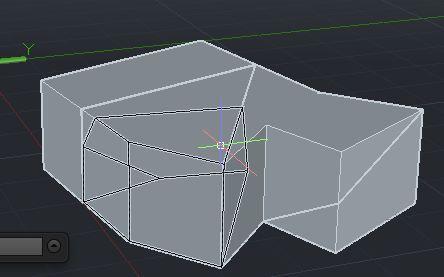
- If you have a gap between solids you could redo the path and extrusion or you could use LOFT to create a solid that joins the separate solids:
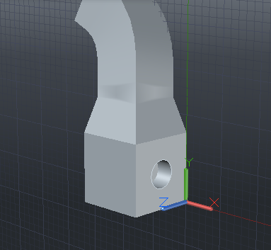
- Create a circle on the face and use PRESSPULL to create a hole:
- Another option for solidediting faces is copy. This lets you select a face and make a copy. The copied face becomes a region that can later be extruded:
- Save your drawing.
Modifying holes.
- Type f for face and press <RETURN>.
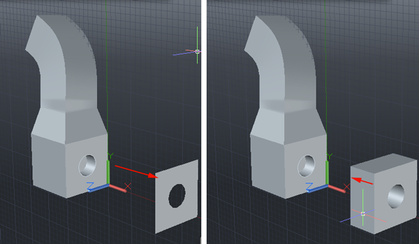
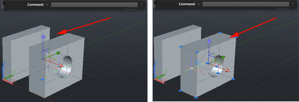
- Type m for move and press <RETURN>. Select the hole, a base point or displacement and a second point of displacement.
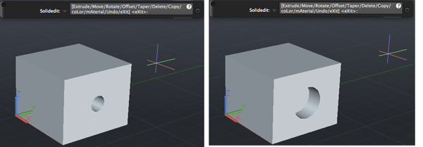
To change the diameter of a hole you can use SOLIDEDIT with faces and offset. A positive offset value will increase the size of the solid volume (making a smaller hole). A negative offset distance will decrease the volume of the solid (making a larger hole):
Solid Model Editing: Body
- Create a new drawing and use the acad3d.dwt template. Change the units to millimeters.
- Add a 20x20x20 box.
- Call SOLIDEDIT and press <RETURN>.
- Type b and press <RETURN> to select the body of the 3D object.
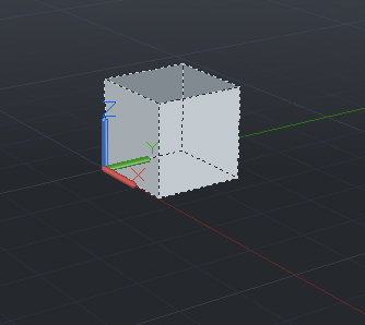
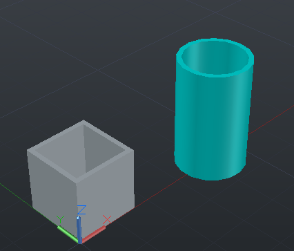
- Shelling is a way to make a solid hollow. To shell the BOX type Sh and press <RETURN>.
- Click once on the object to select it:
- Now click on the faces you want to remove. To create tubes, you need to select opposite faces (like the top and bottom). Then press <RETURN>:
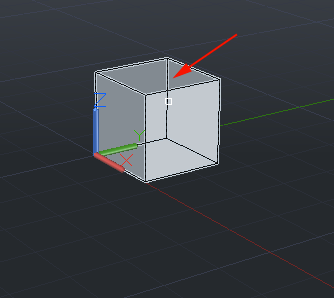
- Specify the amount to shell. Make the value 1.5 and press <RETURN>:

- Create a cylinder and use SOLIDEDIT to create a tube with a 1.5mm wall thickness.
- To change the color of an object you can also use SOLIDEDIT.
- Call SOLIDEDIT and press <RETURN>.
- Type f to select the faces of the 3D object and press <RETURN>.
- Type col to select color and press <RETURN>.
- Click on the object then type ALL and <RETURN>.
- Select a color and press OK:
- Another use of SOLIDEDIT with Body is separating solids. This command comes in handy when you are editing a solid that seems to have separate parts, but is actually one unified solid. You can use seParate solids to create separate solids:
Slice
Another way to separate parts or just cut a solid is with SLICE. Slice enables you to cut a solid into two pieces.- Create a new drawing and use acad3d.dwt template.
- Set the units to millimeters.
- On the command line type Z and press <RETURN> and then type A and <RETURN>. This will zoom you in so that you can get an overall view of your work.
- Create a box or extrude a polyline
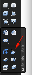
- Type Slice or SL and press <RETURN>:
- At the Select objects to slice: prompt, click the object you would like to slice and press <RETURN>.
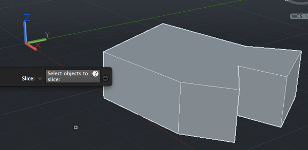
The Slice command would then slice all the solids through the plane indicated. - Select a point
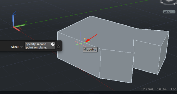
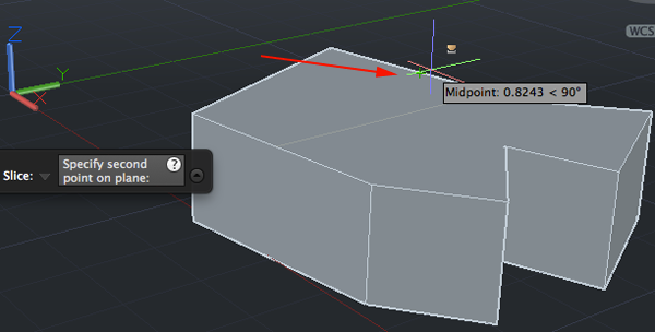
- Select another point
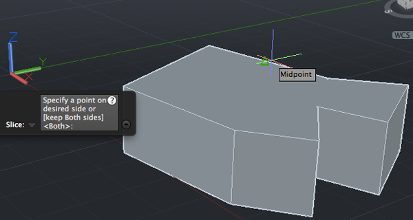
- Type both if not selected and press <RETURN> to keep both sides of the slice
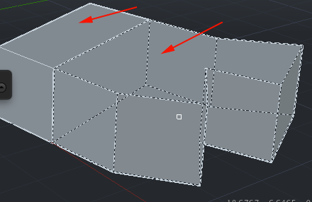
- Look at the command line and create a number of slices based on the options (3points, ZAxis, XY, etc)
Source:
Cross, Nigel. Engineering Design Methods. Chichester: Wiley, 1989.
Omura, George; Graham, Richard (Rick) (2010-11-09). Mastering AutoCAD for Mac (Kindle Location 18101). Wiley. Kindle Edition.
Shih, Randy H. AutoCAD 2014 Tutorial Second Level: 3D Modeling. Mission, KS: SDC Publications, 2013. Print.
Shumaker, Terence M., and David A. Madsen. AutoCad and Its Applications: Basics. Tinley Park, IL: Goodheart-Willcox, 2004. Print.
Watson, David. "Learn AutoCAD with Our Free Tutorials." AutoCAD Tutorials, Articles & Forums. N.p., n.d. Web. 05 Jan. 2015.