Blender
Blender's Extra Objects
While you could create an SVG file of a gear, Blender provides a very simple way to create gears and a few extra objects.
- Open Blender
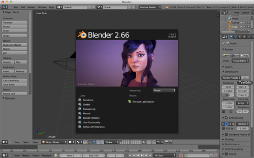
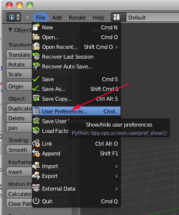
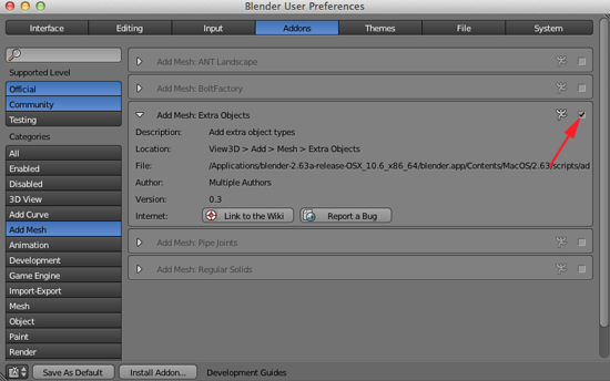
- If you have not enabled Extra Objects navigate to File>User Preferences or type (CMD+,).
- Click on Addons
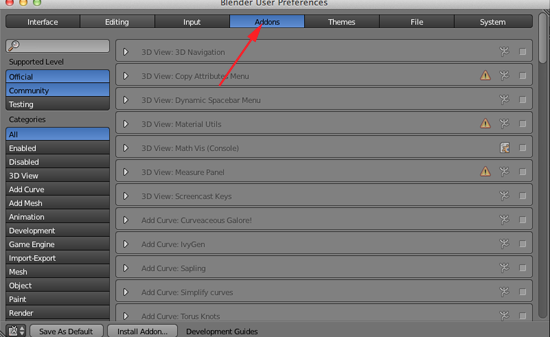
- Click on Add Mesh and toggle open Extra Objects and enable this Addon
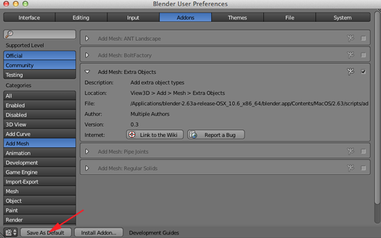
- Click on Save As Default
Gears
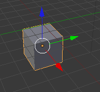
- If the cube is not selected (if there is not an orange line around it), RIGHT click on it to select it:
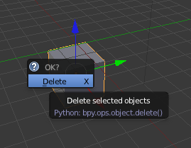
- Press X and click on Delete to delete the cube.
- Set your Viewport to Top Ortho (7,5)
- Place your 3D cursor in the center.
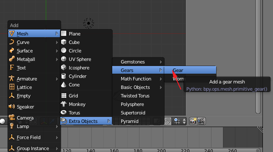
- Press SHIFT+A. Select Mesh>Extra Objects>Gears>Gear
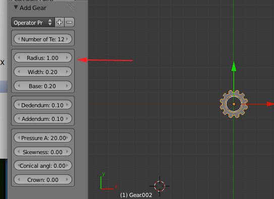
- Adjust the gear parameters in the tool shelf. You will have to make all the changes to the parameters before you make any transformations.
You use gears to slow down a motor and give it more strength.
Torque refers to rotating strength. If the input gear is smaller, your larger gear will move slower, but the torque will be stronger.
As the speed increases, the strength of the torque decreases (large input).
As speed decreases, strength increases (small input).
You also use gears when your mechanism that is controlled by a motor is separated from the motor by geometry. The gears allow you to transfer the rotation of the motor across this geometry. When designing, you will often work from mechanism back to motor.
You could use gears with the same number of teeth to move the rotation.
Gears are comparable to continuously applied levers; as one tooth is engaging, another is disengaging. The amount of teeth on each gear wheel affects the action on the gear wheel it engages or meshes with. The gear wheel being turned is called the input gear and the one it drives is called the output gear. Gears with unequal numbers of teeth alter the speed between the input and output. This is referred to as the gear ratio.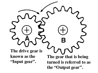
Gears also alter the direction of rotation. In the above example gear wheel A is rotating clockwise, but as it turns, gear wheel B is moved anti-clockwise.
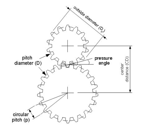
If you know any two things about a gear—outer diameter and number of teeth—you can use some simple equations to find everything else you need to know, including the correct center distance between them.- Number of Teeth (N)
- How many teeth are there in the gear
- Pitch Diameter (D):
- The circle on which two gears effectively mesh, about halfway through the tooth. The pitch diameters of two gears will be tangent when the centers are spaced correctly.
- Diametral Pitch (P):
- The number of teeth per inch of the circumference of the pitch diameter. Think of it as the density of teeth—the higher the number, the smaller and more closely spaced the teeth on a gear. Common diametral pitches for hobby-size projects are 24, 32, and 48. The diametral pitch of all meshing gears must be the same.
- Circular Pitch (p) = pi / P:
- The length of the arc between the center of one tooth and the center of a tooth next to it. This is just pi (ï€ = 3.14) divided by the diametral pitch (P). Although rarely used to identify off the shelf gears, you may need this parameter when modeling gears in 2D and 3D software like we're doing here. As with diametral pitch, the circular pitch of all meshing gears must be the same.
- Outside Diameter (Do):
- The biggest circle that touches the edges of the gear teeth. You can measure this using a caliper like Sparkfun.com's # TOL-00067.
Note: Gears with an even number of teeth are easiest to measure, since each tooth has another tooth directly across the gear. On a gear with an odd number of teeth, if you draw a line from the center of one tooth straight through the center across the gear, the line will fall between two teeth. So, just be careful using outside diameter in your calculations if you estimated it from a gear with an odd number of teeth. - Center Distance (C):
- Half the pitch diameter of the first gear plus half the pitch diameter of the second gear will equal the correct center distance. This spacing is critical for creating smooth running gears.
- Pressure Angle:
- The angle between the line of action (how the contact point between gear teeth travels as they rotate) and the line tangent to the pitch circle. Standard pressure angles are, for some reason, 14.5&Acir;° and 20°. A pressure angle of 20° is better for small gears, but it doesn't make much difference. It's not important to understand this parameter, just to know that the pressure angle of all meshing gears must be the same.
- Addendum:
- how much the tooth protudes beyond the pitch radius
- Dedendum:
- how deep goes the tooth before any fillet takes place
- Pressure angle:
- The angle between the radial direction and the tangent to the tooth at the pitch circle. 20 is a good value.
Some Rules
The value of the base circle is based on pressure angle.- The smaller the pressure angle, the smaller the base radius
- The addendum must be less than the dedendum
- The dedendum must be more than the difference between the pitch and the base radius.
All of these gear parameters relate to each other with simple equations.To Get You Have Equation Diametrical Pitch(P)
Number of teeth per unit lengthCircular Pitch(p)
Number of Teeth(N) & Pitch Diameter(D)
Number of Teeth(N) & Outside Diameter (Do)P=π/p
P=N/D
P=(N+2)/Do(approx)Circular Pitch(p)
Length of the arc from one tooth to the nextDiametrical Pitch (P) p=π/P Pitch Diameter(D) Number of Teeth(N) & Diametrical Pitch(P)
Outside Diameter (Do) &Diametrical Pitch(P)D=N/P
D=Do-2/PNumber of Teeth(N) Diametrical Pitch(P) & Pitch Diameter(D) N=P*D Center Distance(CD) Pitch Diameter(D)
Number of Teeth(N) & Diametrical Pitch(P)CD=(D1+D2)/2CD=(N1+N2)/2P
Stepping down has the advantage of producing more power although at a slower rate.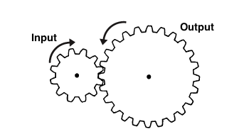
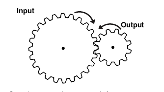 This
Stepping up produces a much faster output
speed, but mechanically delivers less power
CALCULATING RATIOS
If the input gear (A) has 10 teeth and the output gear (B) 30 teeth, then the ratio is termed 3 to 1 and is written down as 3:1Ratio = No. of teeth on the output gear B (30)> No. of teeth on the input gear A (10) = 3/1 and is written down as 3:1
Simply divide the amount of teeth from the output by the input gear to work out the ratio. In the above example, for every complete revolution of the input gear the output turns 1/3 of the way round. In other words it takes three turns of A to rotate B once. This means you are slowing down the action and is referred to in engineering terms as Stepping Down. If B were the input gear and A the output gear, then the opposite happens and we Step Up. Then with one turn of the input gear the output gear would turn three revolutions, giving a ratio of 1:3.
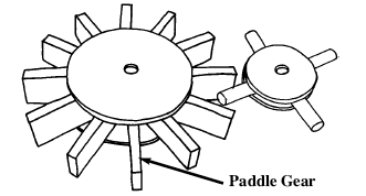
parallel gears work in a similar way to the In line ones but are much easier to construct. The larger one uses popsicle sticks instead of dowel and is referred to as a Paddle gear.
Designing
When designing and making gear wheels you need to apply a little common sense. For example, the load or pressure put on the gears in automata are usually very small compared to that of a car gear box. This allows you to get away with things that you couldn't in other machines. However, you still have to follow some simple engineering guidelines. You will need to identify what you want to get from the gears. Try running through this simple check list;- Do you want the gears to step up or
step down? (speed up or slow down
the performance).
- Do you want the gears to run
parallel, or at an angle of 90° to
change the direction of the drive?
- What size do you need to make
them? (small space means making
smaller gears and this can get tricky).
- You need to set your parameters before doing any transforms or using modifiers. Once you have your gears, scale them up in Blender
- RIGHT+click on the gear or gears and select File>Export>STL(.stl) Save the stl and open in MakerWare or ReplicatorG.
Gem Stones
- Create a new Bender document.
- If the cube is not selected (if there is not an orange line around it), RIGHT click on it to select it:

- Press X and click on Delete to delete the cube.

- Set your Viewport to Top Ortho (7,5)
- Place your 3D cursor in the center.
- Press SHIFT+A. Select Mesh>Extra Objects>Gemstones>Diamond.
- You will have to adjust the parameters before making any transformations. Adjust the gemstone parameters in the tool shelf
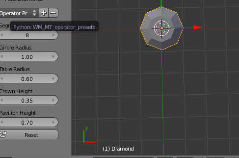
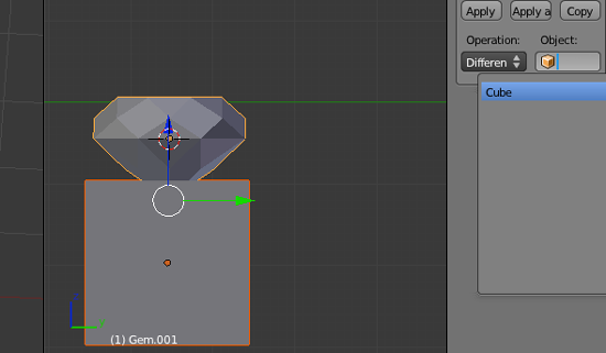
- If you want to attach the gemstone to a ring, you might want to take a cube and boolean difference the pointed part of the gemstone.
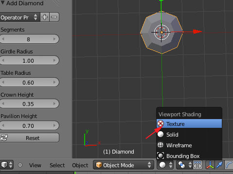
- If you add a a gem and modify the parameters, you might create problems with your mesh. To see the issues, switch from Solid to Texture viewport shading:
- If you see a problem like this:
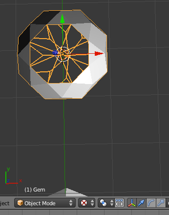
Toggle into Edit Mode
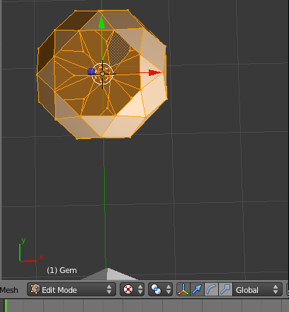
- Press CTRL+N or navigate to the Mesh>Normals>Recalculate Outside
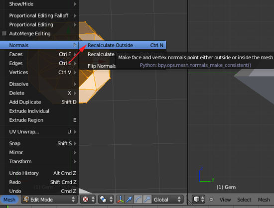
- RIGHT+click on the gem and select File>Export>STL(.stl) Save the stl and open in MakerWare or ReplicatorG.
Importing and Extruding .svg files
- Open Blender.
- Click on File>Import>Scalable Vector Graphic (.svg) and navigate to your .svg file and click on Import .SVG button in the top right corner.
- RIGHT+click on the imported file so that it is selected.
- In the left panel select Origin to Geometry
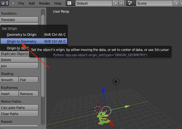
- Click on Object Data in the Right Panel:
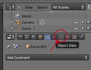
- This will open the Object Data panel:
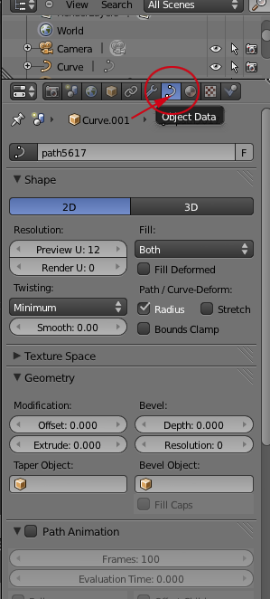
- If it isn't open, toggle open the Geometry panel

- CTRL+click on Extrude
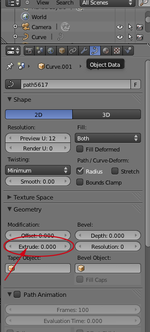
- Change the extrude value to 1
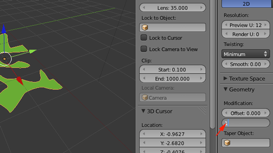
- In the Viewport press N. And resize your shape by pressing S and scaling up so that your width matches your your width from the original .svg file:
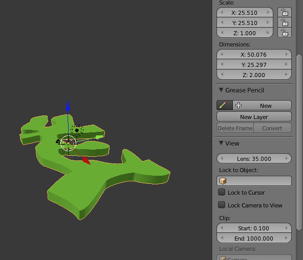
- Set the z to however high you want your tile.
- Convert the shape to a mesh by selecting Object>Convert To>Mesh from Curve
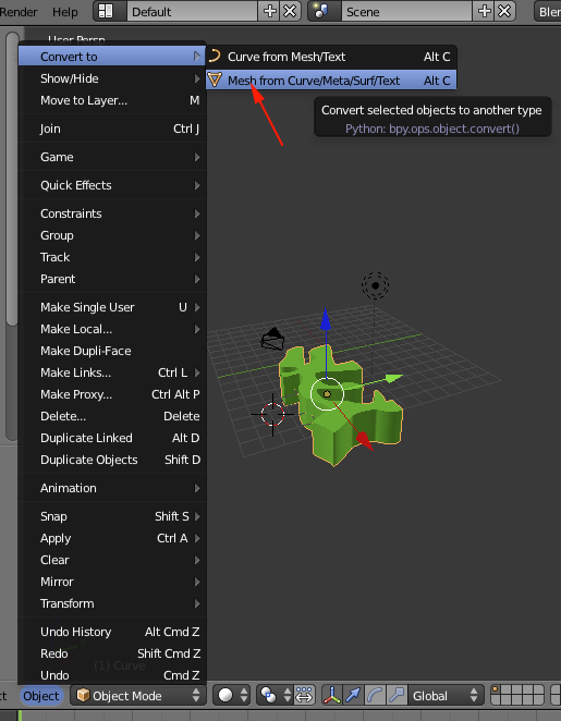
- Select the object if it is not selected and select File>Export>STL(.stl) Save the stl and open in MakerWare.
Spin Tool and Blender
Blender's Spin tool works by making copies of the selected vertices in a radial array around an axis indicated by the 3d cursor. Each copy of vertices are connected to previous vertices that corresponds to it with necessary geometry (edges and planes).Using a Profile
- Open Blender
- If the cube is not selected (if there is not an orange line around it), RIGHT click on it to select it

- Press X and click on Delete

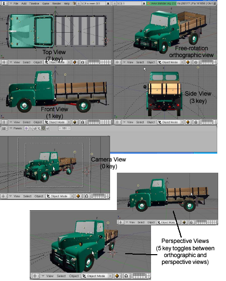
- Set your viewport to Front View by pressing the number 1 on your keyboard.
- Press Num 5 to switch out of perpective mode and into orthogonal mode.
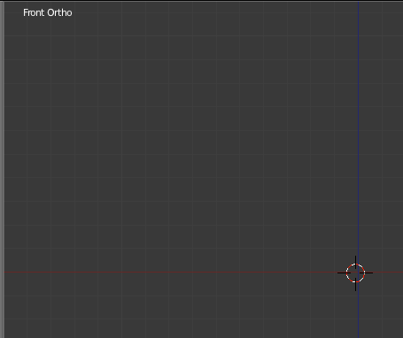
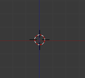
- Align the 3D cursor to the intersection of red and blue lines:
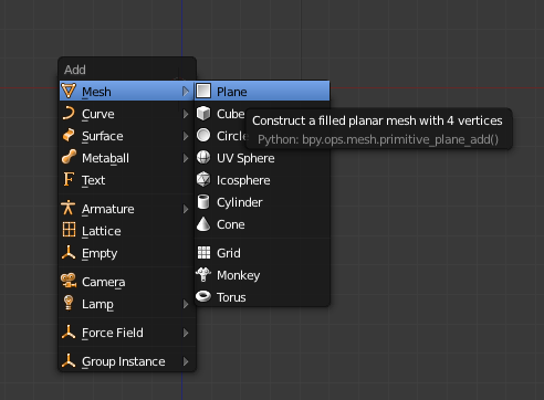
- Add a mesh that is a plane by pressing SHIFT+A.
- Press Tab to switch from Object Mode to Edit Mode.
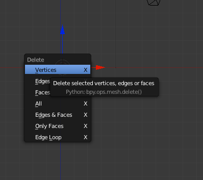
- Delete all the vertices by pressing X:
-
CTRL+LMB to add a new vertex point at the depth of the 3D cursor
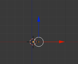
- If the axes bother you
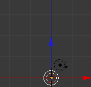
toggle off the 3D manipulator
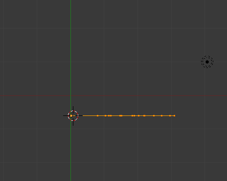
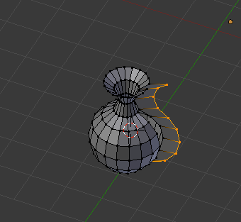
- Continue to use CTRL+LMB to drag out a profile of a vase:
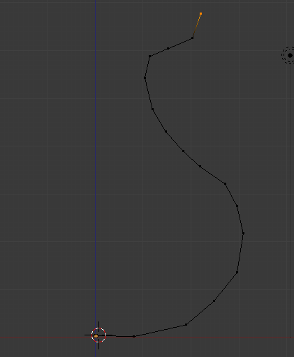
- Select all the points by press A to deselt all and A again to select all:
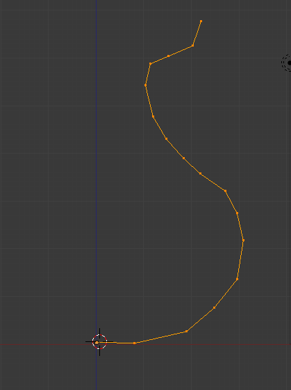
- Go to Top View (7)
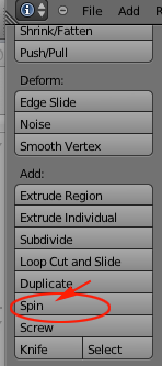
- Select spin:
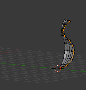
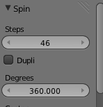
- Open up the Spin Menu and adjust rotation to 360 and segments to some value 16 or greater
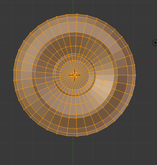
- You will have an extra set of vertices
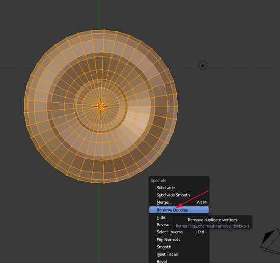
- Select All by pressing A and then press W to remove doubles
- Press A again to deselect.
- Edit as you see fit. To grab vertices, toggle the limit

-
Press B for boundary select and drag a box around what you want to edit, press G to grab and move your mouse in a direction
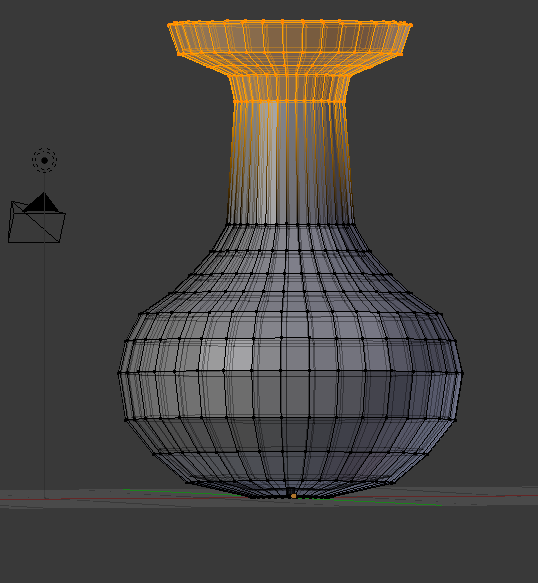
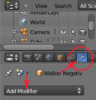
- Add a Modifier by clicking on the Wrench on the right hand side and selecting Add Modifier:
- Select the
solidify modifier and scrub to add thickness
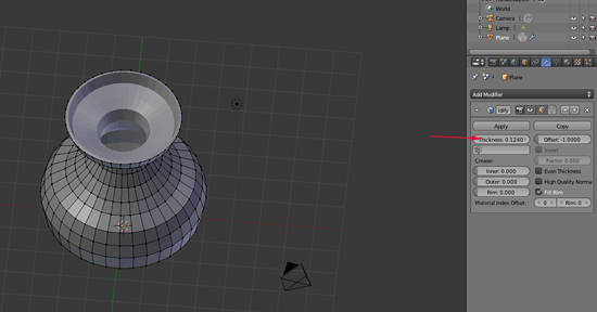
- Press Tab to toggle back to Object mode.
- Click Apply
- Add another Modifier. This time add Multiresolution
- Click on subdivide a few times:
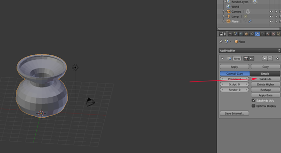
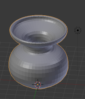
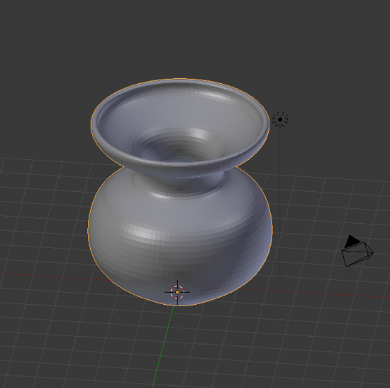
- Click Apply
- Select the model
- To export the model as an STL, select the model then choose File>Export>STL(stl).
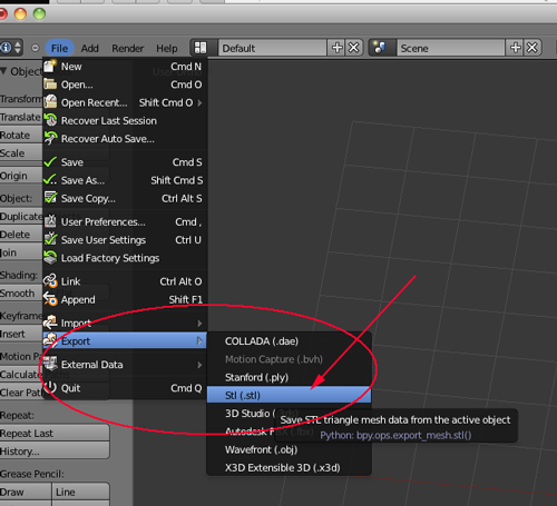
- Give the file a name with the .stl extension and save.
- Slice and print. You will need to scale the model up in MakerWare in order to get a decent vase.
Using BSurfaces with Blender
BSurfaces is a is a Blender add-on modeling tool that combines freehand strokes, beziér curves and loose edges to generate polygonal surfaces.- If you don't have Blender installed, download it from blender.org and install it.
- Download BSurfaces_v15_for_blender_263.zip
- Open Blender
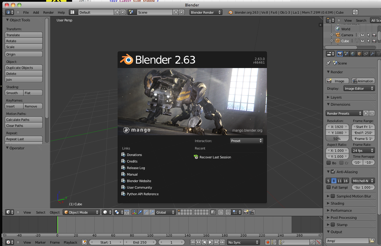
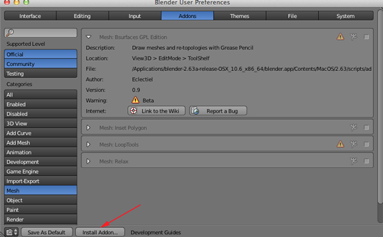
- Open User Preferences

- Navigate to Addons

- If you have BSurfaces GPL Edition vo.9 active, deactivate it
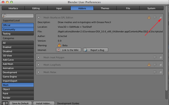
- Click Install Addon... to install the BSurfaces.py

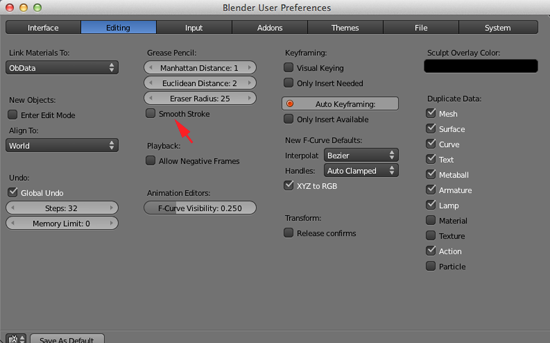
- Navigate to Editing
- Disable the option Smooth strokes if it is enabled.
- Click on Save As Default

- Create a New Document (File>New Document)
-
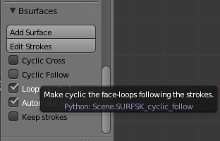
To find the BSurfaces panel, select a mesh object, go to Edit Mode, and navigate to the bottom of the 3D view toolshelf:
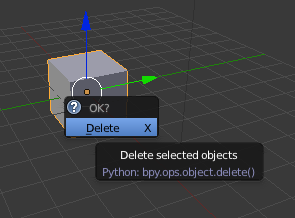
- Press X and click on Delete to delete the default cube
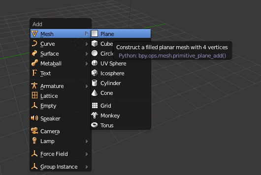
- Press SHIFT+A to add a mesh plane
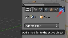
- Click on Object Modifiers
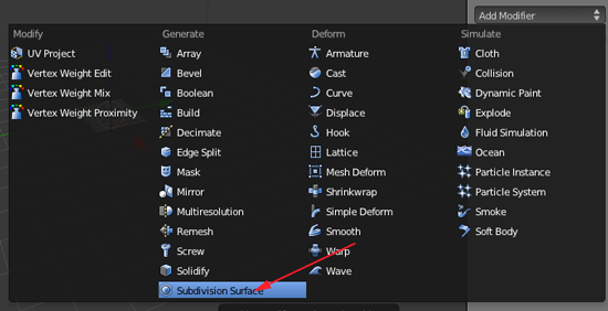
- Click on Add Modifier and add a Subdivision modifier
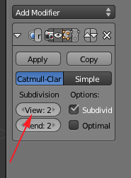
- Set View to 2:
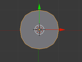
- Add a second viewport by dragging the upper right corner over to the left.
- Toggle off the Toolshelf by pressing T.
- Set the left side to Top Ortho (7,5)
- Set the right viewport to Right Ortho (3,5)
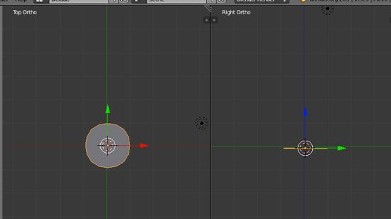
- In Top Ortho view add a Curve>Beziér Circle by pressing SHIFT+A
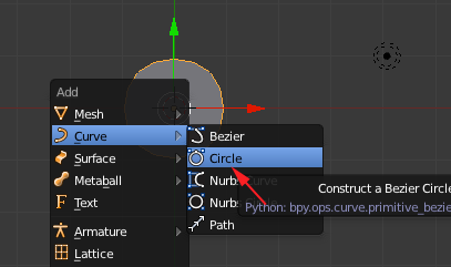
- Your circle will be slightly larger than your plane. Press S and scale the circle to fit the plane

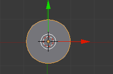
- Press Tab to go to Edit Mode
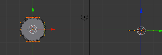
- Press SHIFT+D to duplicate the curve. Then press G and Z to move the duplicated curve up. Then press S to scale the curve

- Continue to duplicate, move and scale as desired:
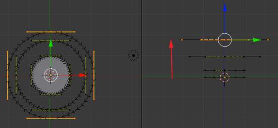
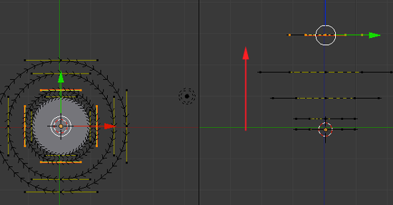
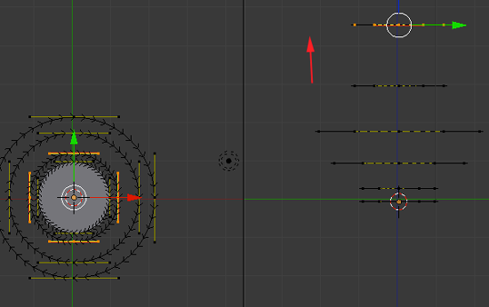
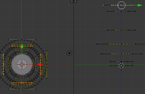
- Press Tab to go to Object Mode
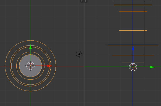
- You want to add the plane to the curve. RIGHT+click on the plane
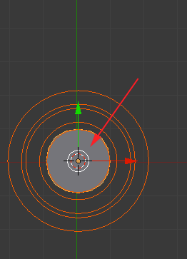
- Press Tab to go to Edit Mode
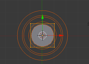
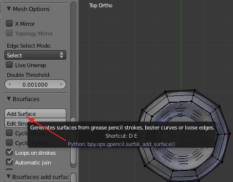
- Navigate to the Bsurface panel and select Add Surface
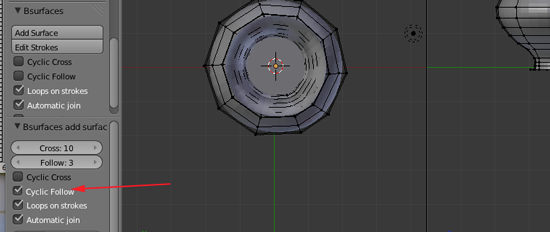
- In the new panel that appears enable Cyclic Follow
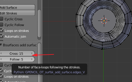
- In the new panel that appears adjust the Cross and the Follow values
- Press Tab to go to Object Mode
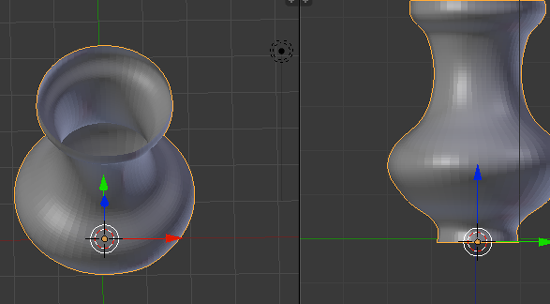
- Click on Object Modifiers

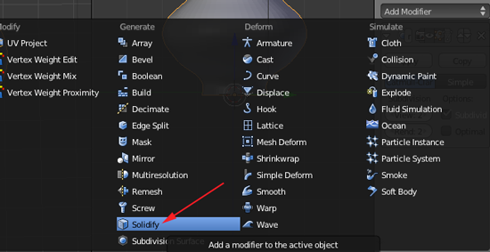
- Click on Add Modifier and add a Solidify modifier
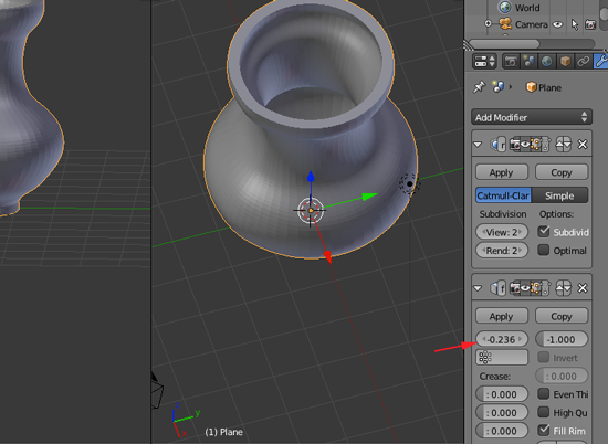
- Adjust the parameters of the modifier
- To export the model as an STL, select the model then choose File>Export>STL(stl).

- Give the file a name with the .stl extension and save.
- Slice and print. You will need to scale the model up in ReplicatorG or MakerWare in order to get a decent vase.
Using the Boolean Modifier with Blender
Constructive solid geometry (CSG) is a technique used in solid modeling. Using this typeof modeling allows you to create a complex objects by using Boolean operators to combine objects. Often CSG presents a model or surface that appears complex, but is actually little more than cleverly combined or decombined objects.The simplest solid objects used when modeling are called primitives—cubes, cylinders, pyramids, spheres, cones. These are Blender's primitives:
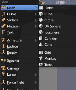
When using Constructive solid geometry , an object is constructed from primitives by means of combining operations. These operations are typically Boolean operations: union, intersection and difference.
Constructive solid geometry is used in cases where simple geometric objects are desired, or where mathematical accuracy is important.
Boolean Intersection
- You should have a document with the default Cube. If you do not have the cube, you can select File>Load Factory Settings. If you do reload the factory sttings, you'll have to reset your user preferences.
- Add a UV Sphere by pressing SHIFT+A
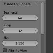
- In the left panel adjust the Sphere properties
- While the sphere is selected, RIGHT+click on the Cube.
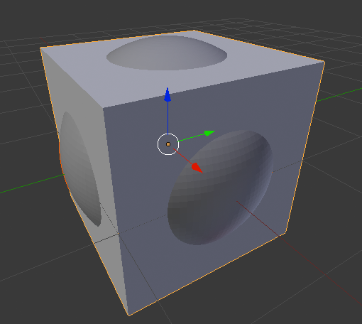
- Select Object Data Modifier

- Select Add Modifier and choose Boolean
- Select Intersection. Click on the Object icon and select Sphere
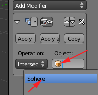
- Depending on the complexity of your mesh, you may have to wait for Blender to process the request
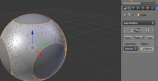
- Click Apply
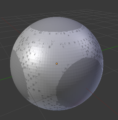
- Select the Sphere
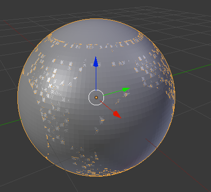
- Move the sphere by pressing G and X and dragging the Sphere along the X axis
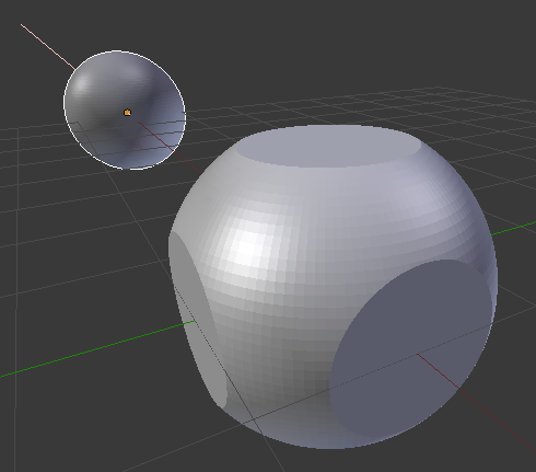
Boolean Union
- Select File>New. You should have a new document with the default Cube. If you do not have the cube, you can select File>Load Factory Settings. If you do reload the factory sttings, you'll have to reset your user preferences.
- Add a UV Sphere by pressing SHIFT+A
- In the left panel adjust the Sphere properties

- While the sphere is selected, RIGHT+click on the Cube.

- Select Object Data Modifier

- Select Add Modifier and choose Boolean
- Select Union. Click on the Object icon and select Sphere
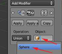
- Depending on the complexity of your mesh, you may have to wait for Blender to process the request
Press Apply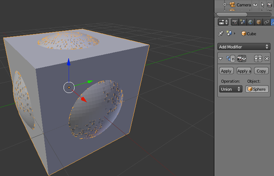
- Select the Sphere and move it by pressing G and X and dragging the Sphere along the X axis
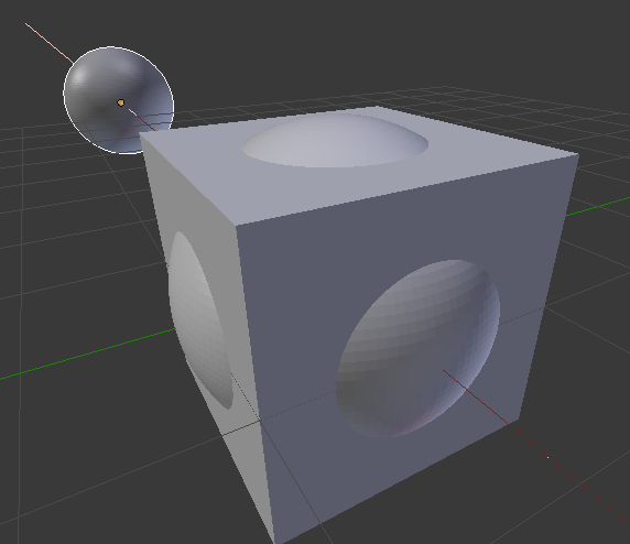
Boolean Difference
- Select File>New. You should have a new document with the default Cube. If you do not have the cube, you can select File>Load Factory Settings. If you do reload the factory sttings, you'll have to reset your user preferences.
- Add a UV Sphere by pressing SHIFT+A
- In the left panel adjust the Sphere properties

- While the sphere is selected, RIGHT+click on the Cube.

- Select Object Data Modifier

- Select Add Modifier and choose Boolean
- Select Difference. Click on the Object icon and select Sphere
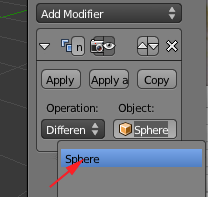
- Depending on the complexity of your mesh, you may have to wait for Blender to process the request
Press Apply. Select the Sphere and move it by pressing G and X and dragging the Sphere along the X axis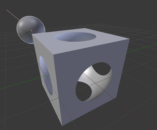
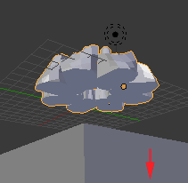
- I tend to use difference a lot. Not only do I use it to create holes, but I often use it to slice off sections of a mesh. This comes in handy when the bottom of a mesh is uneven and cannot lie flat on the build plate.
Here the cube was used to slice off the bottom of a mesh and then it was moved down along the Z axis
Using the Array Modifier with Blender
The Array modifier creates an array of copies of the base object, with each copy being offset from the previous one in a number of possible ways.This modifier can be useful for creating complex repetitive shapes.
Multiple array modifiers may be active for an object at the same time.
- Open Blender
- If the cube is not selected (if there is not an orange line around it), RIGHT click on it to select it:

- Move the cube along the x axis by pressing G and X and moving your cursor
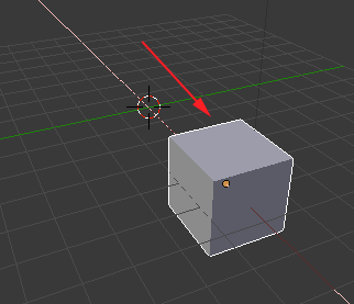
- Make sure the 3D cursor is positioned in the center

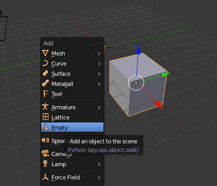
- Add an Empty object by pressing SHIFT+A
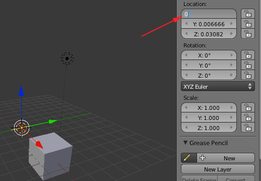
- Press N to open the right panel and make adjust the location so that the Empty is in the center
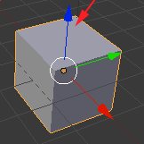
- RIGHT+click on the cube to select it
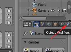
- Click on Object Modifier
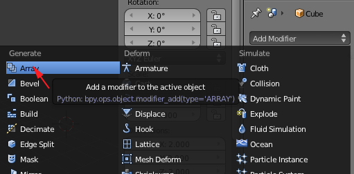
- Click on Add Modifier and select Array
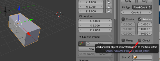
You can also use this modifier to create a matrix of your mesh which can then be printed. - Click on Object
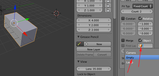
- Click on the cube icon and select Empty
- Deselect Relative
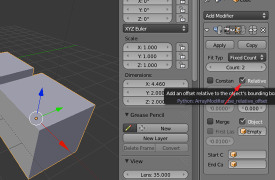
- Change count to 8
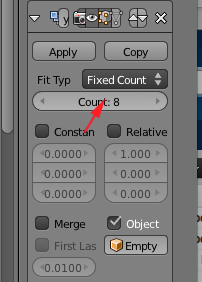
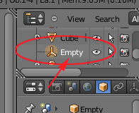
The original object used as a start is placed at the start of the array, as if it were in position -1, an array step before the first array copy. - Select Empty in the Scene panel
- Click on the Rotate manipulator
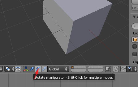
- Click and drag on the blue line to rotate the cubes around the Empty
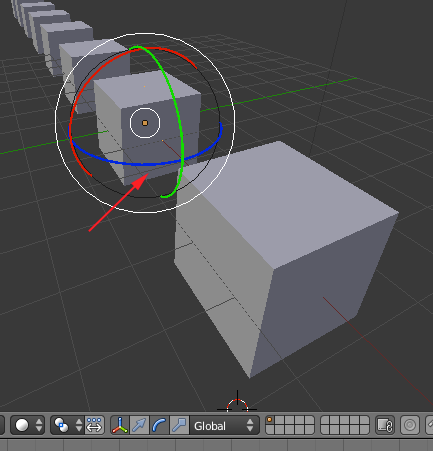
- You can adjust the rotation and the location to move the cubes.
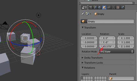
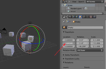
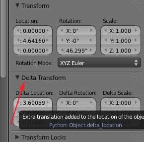
- You can adjust the Delta location to move the cubes
- Select the cube and adjust the Constant Offset

- Select Merge and first and Last
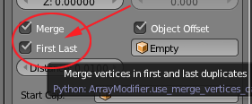
If enabled, vertices in each copy will be merged with vertices in the next copy that are within the given distance. If Merge is activated, and the Start cap is near enough of the first copy, they will be merged. - From Object Mode press Tab to go to Edit Mode

- In Edit Mode you can modify the original mesh and the copies will incorporate those changes.
You can subdivide the cube by pressing W and clicking on Subdivide:

You can turn on Proportional editing by pressing O:
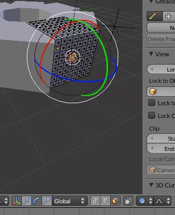
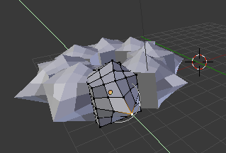
You can even add another mesh in Edit Mode: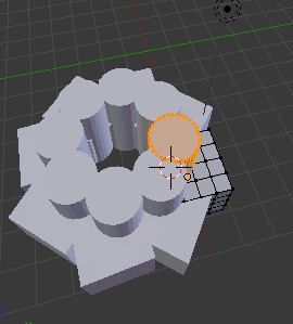
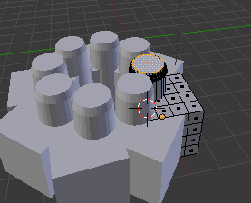
- When your object is complete, toggle back to Object Mode.
- Select the object if it is not selected and select File>Export>STL(.stl) Save the stl and open in MakerWare or ReplicatorG.
New York State Learning Standards
Mathematics, Science, and Technology
-
STANDARD 1
Analysis, Inquiry, and Design: ENGINEERING DESIGN
Key Idea 1: details
Engineering design is an iterative process involving modeling and optimization (finding the best solution within given constraints); this process is used to develop technological solutions to problems within given constraints. (Note: The design process could apply to activities from simple investigations to long-term projects.)Elementary 1.1 Describe objects, imaginary or real, that might be modeled or made differently and suggest ways in which the objects can be changed, fixed, or improved 1.2 Investigate prior solutions and ideas from books, magazines, family, friends, neighbors, and community members 1.3 Generate ideas for possible solutions, individually and through group activity; apply age-appropriate mathematics and science skills; evaluate the ideas and determine the best solution; and explain reasons for the choices 1.4 Plan and build, under supervision, a model of the solution using familiar materials, processes, and hand tools 1.5 Discuss how best to test the solution; perform the test under teacher supervision; record and portray results through numerical and graphic means; discuss orally why things worked or didn't work; and summarize results in writing, suggesting ways to make the solution better
Intermediate T1.1 Identify needs and opportunities for technical solutions from an investigation of situations of general or social interest. T1.1a Identify a scientific or human need that is subject to a technological solution which applies scientific principles √ T1.2 Locate and utilize a range of printed, electronic, and human information resources to obtain ideas. √ T1.2a Use all available information systems for a preliminary search that addresses the need. √ T1.3 Consider constraints and generate several ideas for alternative solutions, using group and individual ideation techniques (group discussion, brainstorming, forced connections, role play); defer judgment until a number of ideas have been generated; evaluate (critique) ideas; and explain why the chosen solution is optimal. √ T1.3a Generate ideas for alternative solutions √ T1.3b Evaluate alternatives based on the constraints of design √ T1.4 Develop plans, including drawings with measurements and details of construction, and construct a model of the solution, exhibiting a degree of craftsmanship. √ T1.4a Design and construct a model of the product or process √ T1.4b Construct a model of the product or process √ T1.5 In a group setting, test their solution against design specifications, present and evaluate results, describe how the solution might have been modified for different or better results, and discuss trade-offs that might have to be made. √ T1.5a Test a design √ T1.5b Evaluate a design √
Commencement 1.1 Initiate and carry out a thorough investigation of an unfamiliar situation and identify needs and opportunities for technological invention or innovation 1.2 identify, locate, and use a wide range of information resources including subject experts, library references, magazines, videotapes, films, electronic data bases and online services, and discuss and document through notes and sketches how findings relate to the problem 1.3 generate creative solution ideas, break ideas into the significant functional elements, and explore possible refinements; predict possible outcomes using mathematical and functional modeling techniques; choose the optimal solution to the problem, clearly documenting ideas against design criteria and constraints; and explain how human values, economics, ergonomics, and environmental considerations have influenced the solution 1.4 develop work schedules and plans which include optimal use and cost of materials, processes, time, and expertise; construct a model of the solution, incorporating developmental modifications while working to a high degree of quality (craftsmanship) 1.5 in a group setting, devise a test of the solution relative to the design criteria and perform the test; record, portray, and logically evaluate performance test results through quanitative, graphic, and verbal means; and use a variety of creative verbal and graphic techniques effectively and persuasively to present conclusions, predict impacts and new problems, and suggest and pursue modifications -
STANDARD 2
INFORMATION SYSTEMS
Key Idea 1: details
Information technology is used to retrieve, process, and communicate information as a tool to enhance learning.Elementary 1.1 Use computer technology,traditional paper-based resources,and interpersonal discussions to learn, do, and share science in the classroom √ 1.2 Select appropriate hardware and software that aids in wordprocessing, creating databases, telecommunications, graphing, data display, and other tasks √ 1.3 Use information technology to link the classroom to world events
Intermediate 1.1 Use a range of equipment and software to integrate several forms of information in order to create good-quality audio, video, graphic, and text-based presentations. 1.2 Use spreadsheets and database software to collect, process, display, and analyze information. Students access needed information from electronic databases and on-line telecommunication services. 1.3 Systematically obtain accurate and relevant information pertaining to a particular topic from a range of sources, including local and national media, libraries, muse- ums, governmental agencies, industries, and individuals. 1.4 Collect data from probes to measure events and phenomena. 1.4a Collect the data, using the appropriate, available tool 1.4b Organize the data 1.4c Use the collected data to communicate a scientific concept √ 1.5 Use simple modeling programs to make predictions.
Physics 1.1 Understand and use the more advanced features of word processing, spreadsheets, and database software. 1.2 Prepare multimedia presentations demonstrating a clear sense of audience and purpose. (Note: Multimedia may include posters, slides, images, presentation software, etc.) √ 1.2a Extend knowledge of physical phenomena through independent investigation, e.g., literature review, electronic resources, library research 1.2b Use appropriate technology to gather experimental data, develop models,and present results √ 1.3 Access, select, collate, and analyze information obtained from a wide range of sources such as research databases, foundations, organizations, national libraries, and electronic communication networks, including the Internet. 1.3a Use knowledge of physics to evaluate articles in the popular press on contemporary scientific topics 1.4 Utilize electronic networks to share information. √ 1.5 Model solutions to a range of problems in mathematics, science, and technology, using computer simulation software. √ 1.5a Use software to model and extend classroom and laboratory experiences,recognizing the differences between the model used for understanding and real-world behavior √ -
STANDARD 5
Technology: Engineering Design
Key Idea 1:
(See Standard 1:ENGINEERING DESIGN) -
STANDARD 5
Technology: Computer Technology
Key Idea 3: details
Computers, as tools for design, modeling, information processing, communication, and system control, have greatly increased human productivity and knowledge.Elementary 3.1 Identify and describe the function of the major components of a computer system. 3.2 Use the computer as a tool for generating and drawing ideas. √ 3.3 Control computerized devices and systems through programming. √ 3.4 Model and simulate the design of a complex environment by giving direct commands. √
Intermediate 3.1 Assemble a computer system including keyboard, central processing unit and disc drives, mouse, modem, printer, and monitor 3.2 Use a computer system to connect to and access needed information from various Internet sites √ 3.3 Use computer hardware and software to draw and dimension prototypical designs √ 3.4 Use a computer as a modeling tool √ 3.5 Use a computer system to monitor and control external events and/or systems √
Commencement 3.1 Understand basic computer architecture and describe the function of computer subsystems and peripheral devices 3.2 Select a computer system that meets personal needs 3.3 Attach a modem to a computer system and telephone line, set up and use communications software, connect to various online networks, including the Internet, and access needed information using email, telnet, gopher, ftp, and web searches √ 3.4 Use computer-aided drawing and design (CADD) software to model realistic solutions to design problems √ 3.5 Develop an understanding of computer programming and attain some facility in writing computer programs √ -
STANDARD 5
Technology: Technological Systems
Key Idea 4: details
Technological systems are designed to achieve specific results and produce outputs, such as products, structures, services, energy, or other systems.Elementary 4.1 Identify familiar examples of technological systems that are used to satisfy human needs and wants, and select them on the basis of safety, cost, and function. 4.2 Assemble and operate simple technological systems, including those with interconnecting mechanisms to achieve different kinds of movement. 4.3 Understand that larger systems are made up of smaller component subsystems.
Intermediate 4.1 Select appropriate technological systems on the basis of safety, function, cost, ease of operation, and quality of post-purchase support 4.2 Assemble, operate, and explain the operation of simple open- and closed-loop electrical, electronic, mechanical, and pneumatic systems 4.3 Describe how subsystems and system elements (inputs, processes, outputs) interact within systems 4.4 Describe how system control requires sensing information, processing it, and making changes √
Commencement 4.1 Explain why making tradeoffs among characteristics, such as safety, function, cost, ease of operation, quality of post-purchase support, and environmental impact, is necessary when selecting systems for specific purposes 4.2 Model, explain, and analyze the performance of a feedback control system 4.3 Explain how complex technological systems involve the confluence of numerous other systems -
STANDARD 6
Interconnectedness: Common Themes SYSTEMS THINKING:
Key Idea 1: details
Through systems thinking, people can recognize the commonalities that exist among all systems and how parts of a system interrelate and combine to perform specific functions.Elementary 1.1 Observe and describe interactions among components of simple systems. √ 1.2 Identify common things that can be considered to be systems (e.g., a plant population, a subway system, human beings).
Intermediate 1.1 Describe the differences between dynamic systems and organizational systems. 1.2 describe the differences and similarities between engineering systems, natural systems, and social systems. 1.3 Describe the differences between open- and closed-loop systems. 1.4 Describe how the output from one part of a system (which can include material, energy, or information) can become the input to other parts.
Commencement 1.1 Explain how positive feedback and negative feedback have opposite effects on system outputs. 1.2 Use an input-process-output-feedback diagram to model and compare the behavior of natural and engineered systems. 1.3 Define boundary conditions when doing systems analysis to determine what influences a system and how it behaves. -
STANDARD 6
Interconnectedness: Common Themes MODELS:
Key Idea 2: details
Models are simplified representations of objects, structures, or systems used in analysis, explanation, interpretation, or design.Elementary 2.1 Analyze,construct,and operate models in order to discover attributes of the real thing √ 2.2 Discover that a model of something is different from the real thing but can be used to study the real thing √ 2.3 Use different types of models, such as graphs,sketches,diagrams,and maps,to represent various aspects of the real world
Intermediate 2.1 Select an appropriate model to begin the search for answers or solutions to a question or problem. 2.2 Use models to study processes that cannot be studied directly (e.g., when the real process is too slow, too fast, or too dangerous for direct observation). √ 2.3 Demonstrate the effectiveness of different models to represent the same thing and the same model to represent different things.
Physics 2.1 Revise a model to create a more complete or improved representation of the system. 2.2 Collect information about the behavior of a system and use modeling tools to represent the operation of the system. √ 2.2a Use observations of the behavior of a system to develop a model 2.3 Find and use mathematical models that behave in the same manner as the processes under investigation. 2.3a Represent the behavior of real-world systems,using physical and mathematical models √ 2.4 Compare predictions to actual observations, using test models. √ 2.4a Validate or reject a model based on collated experimental data √ 2.4b Predict the behavior of a system,using a model √ -
STANDARD 7
Interdisciplinary Problem Solving STRATEGIES:
Key Idea 2: details
Solving interdisciplinary problems involves a variety of skills and strategies, including effective work habits; gathering and processing information; generating and analyzing ideas; realizing ideas; making connections among the common themes of mathematics, science, and technology; and presenting results.Physics 2.1 Collect,analyze,interpret,and present data,using appropriate tools √ 2.2 When students participate in an extended,culminating mathematics,science,and technology project, then students should: Work effectively—Contributing to the work of a brainstorming group, laboratory partnership, cooperative learning group, or project team; planning procedures; identify and managing responsibilities of team members; and staying on task, whether working alone or as part of a group. √ Gather and process information —Accessing information from printed media, electronic data bases, and community resources and using the information to develop a definition of the problem and to research possible solutions. √ Generate and analyze ideas — Developing ideas for proposed solutions, investigating ideas, collecting data, and showing relationships and patterns in the data. √ Observe common themes—Observing examples of common unifying themes, applying them to the problem, and using them to better understand the dimensions of the problem. √ Realize ideas—Constructing components or models, arriving at a solution, and evaluating the result. √ Present results—Using a variety of media to present the solution and to communicate the results. √
CDOS
Standard 2: Integrated Learning
details
Students will demonstrate how academic knowledge and skills are applied in the workplace and other settings.
Integrated learning encourages students to use essential academic concepts, facts, and procedures in applications related to life skills and the world of work. This approach allows students to see the usefulness of the concepts that they are being asked to learn and to understand their potential application in the world of work.
Elementary 2.1 Identify academic knowledge and skills that are required in specific occupations 2.2 Demonstrate the difference between the knowledge of a skill and the ability to use the skill √ 2.3 Solve problems that call for applying academic knowledge and skills. √
Intermediate 2.1 Apply academic knowledge and skills using an interdisciplinary approach to demonstrate the relevance of how these skills are applied in work-related situations in local, state, national, and international communities 2.2 Solve problems that call for applying academic knowledge and skills √ 2.3 Use academic knowledge and skills in an occupational context, and demonstrate the application of these skills by using a variety of communication techniques (e.g., sign language, pictures, videos, reports, and technology).
Commencement 2.1 Demonstrate the integration and application of academic and occupational skills in their school learning, work, and personal lives. 2.2 Use academic knowledge and skills in an occupational context, and demonstrate the application of these skills by using a variety of communication techniques (e.g., sign language, pictures, videos, reports, and technology) 2.3 Research, interpret, analyze, and evaluate information and experiences as related to academic knowledge and technical skills when completing a career plan. Standard 3a: Universal Foundation Skills
details
Students will demonstrate mastery of the foundation skills and competencies essential for success in the workplace.
Thinking skills
Thinking skills lead to problem solving, experimenting, and focused observation and allow the application of knowledge to new and unfamiliar situations.
Elementary 3.2.1 Use ideas and information to make decisions and solve problems related to accomplishing a task. √
Intermediate 3.2.1 Evaluate facts, solve advanced problems, and make decisions by applying logic and reasoning skills. √
Commencement 3.2.1 Demonstrate the ability to organize and process information and apply skills in new ways. √
- Technology
Technology is the process and product of human skill and ingenuity in designing and creating things from available resources to satisfy personal and societal needs and wants.
Elementary 3.5.1 Demonstrate an awareness of the different types of technology available to them and of how technology affects society.
Intermediate 3.5.1 Select and use appropriate technology to complete a task. √
Commencement 3.5.1 Apply their knowledge of technology to identify and solve problems. √
- Managing Resources
Using resources includes the application of financial and human factors, and the elements of time and materials to successfully carry out a planned activity.Elementary 3.7.1 Demonstrate an awareness of the knowledge, skills, abilities, and resources needed to complete a task. √
Intermediate 3.7.1 Understand the material, human, and financial resources needed to accomplish tasks and activities. √
Commencement 3.7.1 Allocate resources to complete a task. √
- Systems
Systems skills include the understanding of and ability to work within natural and constructed systems.Elementary 3.8.1 Demonstrate understanding of how a system operates and identify where to obtain information and resources within the system. √
Intermediate 3.8.1 Understand the process of evaluating and modifying systems within an organization. √
Commencement 3.8.1 Demonstrate an understanding of how systems performance relates to the goals, resources, and functions of an organization. √
Standard 3b: Career Majors
details
Students who choose a career major will acquire the career-specific technical knowledge/skills necessary to progress toward gainful employment, career advancement, and success in postsecondary programs.- Engineering/Technologies
Core, Specialized and Experiential 3b.1 Foundation Development—Develop practical understanding of engineering technology through reading, writing, sample problem solving, and employment experiences. 3b.2 Technology—Demonstrate how all types of engineering/technical organizations, equipment (hardware/software), and well-trained human resources assist and expedite the production/distribution of goods and services 3b.3 Engineering/Industrial Processes—Demonstrate knowledge of planning, product development and utilization, and evaluation that meets the needs of industry.
- Engineering/Technologies
Using Blender

Blender's interface may seem different from any other program you have used, but in time with some practice, things will make sense:
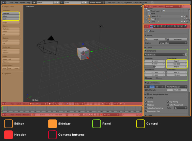
To maximize a window, place the cursor in the window and press SHIFT+spacebar:
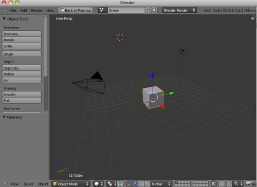
To revert back, press SHIFT and spacebar again.
To toggle the Tool Shelf Panel, press T
To toggle the Properties panel, press N
In addition to creating your own layouts, you can call up premade arrangements from a drop-down list at the top of the screen
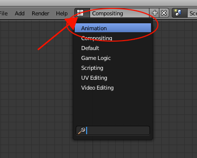
To undo a step, press CTRL+Z. To redo a step, press Shift+CTRL+Z
OPT+G resets the location to the global center
OPT+R resets the rotation so the object stands pright in global coordinates
OPT+S resets the scale to the object's original size
Resizing Windows
- Hold your mouse over the diagonal strips at the top-right or bottom-left corner, the mouse pointer will change to a cross).

- Hold down the LMB (meaning Left Mouse Button) and drag towards the center of the window, or up and to the right.
- As you increase the size of one window, you decrease the size of the other. Blender does not allow the windows to overlap, as they would in other programs. This is why Blender's interface is known as a non-overlapping window interface.
Layers
Blender works with layers much like other programs where objects can be placed in different layers and displayed as needed. It's a good idea to get comfortable with layers because as your scenes get bigger, turning layers on and off can help with the speed of your work and ability to see things better.
The Layer menu can be found on the header strip of the 3D view. If you can't see it, toggle the Show Pull Down Menu button


To move things between layers, select the object with the Right Mouse Button (RMB) and type M for move, then click on the appropriate layer button.
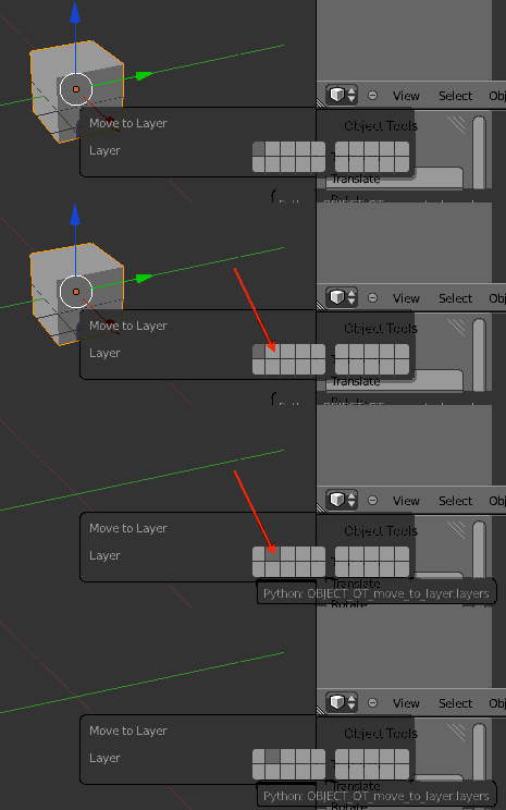
You can select a layer through the numpad. 1 for layer 1, 2 for layer 2, OPT+1 for layer 11, etc
You can turn on layers by clicking on the layer menu:
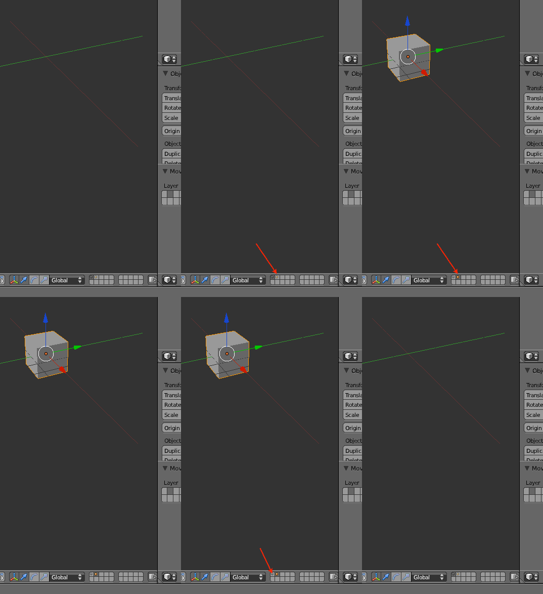
To turn on multiple layers, hold down Shift and click on the buttons.
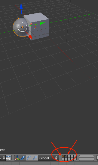
Default Objects
As you move the view around, you will see that there are four objects in your 3D scene by default:
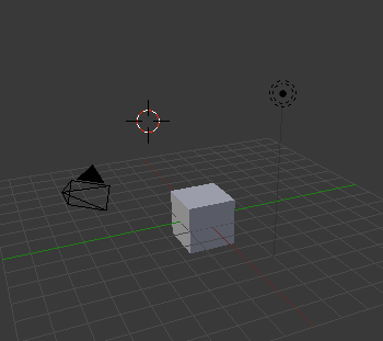
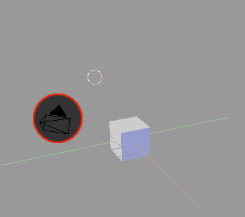
The camera location and rotation will determine what you will see at render time. To see in your 3D viewport what the camera will see, activate that window by pressing NUM0 (remember the 0KEY is different). To switch out of the camera view, drag the MMB.
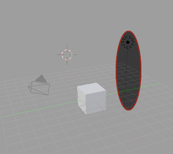
A lamp is simply a light source. It will not be rendered, but the light it provides to the scene will be rendered.

3) A Cube
This object will be rendered. The camera should be pointing at the cube so that you will see it at rendertime.
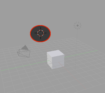
4) The 3D Cursor (works like an 'insertion point')
This is not an object, but a tool for the artist to use to choose where to put new objects in the scene, much like the cursor when you're typing on a word processor (the 'insertion point').
Rotating the view
- Place the mouse pointer over the object in the 3D window.
- Hold down the MMB and drag the mouse from side to side or up and down.
- Hold ALT+LMB
Pressing ZKEY will toggle back and forth between Wireframe Mode and Solid Mode. Pressing NUM5 will toggle between Orthographic and Perspective (perspective looks more natural). This does not affect how your final product will appear, only the way you see your scene while you're creating it.
The Numpad
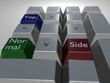
Hold the mouse over your 3D Viewport and press one of the numpad hotkeys:
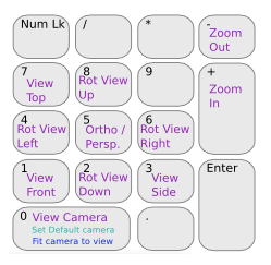
| . |
| The object the viewport orbits around can be changed to a new object by first selecting it with the RMB |
Using CTRL:
|
|
NUM 9 | ||||||
|
|
|
||||||
|
|
|
||||||
[NOTE: selecting an object with the RMB will only work if your viewport is set to 'Object Mode'. Press the TAB key to toggle between 'Edit Mode' and 'Object Mode'.]
In Blender there is a big difference between the number keys on your numberpad and the number keys along the top of the keyboard. For example, NUM7 refers to the number 7 on the numberpad, while 7KEY refers to the number 7 that's above the YKEY and UKEY on the standard US keyboard. If you accidentally pressed 1KEY, 3KEY, or 7KEY during this step and it appears that everything disappeared, you have been changing the layer that you are viewing instead, press the 'key(apostrophe key on the top left) to return to viewing all the layers, or press the 1KEY to get back to viewing layer 1 which should have been originally active.
[NOTE: the 1KEY through 0KEY and alt-1KEY through alt-0KEY switch layers. Hold shift to select more than one layer. `KEY selects all 20 layers.]
Panning the View
To pan the view, you have your choice of alternatives:
- SHIFT+MMB
- SHIFT+ALT+LMB
- and move your mouse.
Alternatively, use the scroll wheel
| SHIFT+Scroll | CTRL+Scroll |
| pan up and down | pan left and right |
Note that you must press SHIFT before MMB, otherwise your view will rotate instead of panning.
Also note, that in Windows XP the simultaneous pressing of SHIFT+ALT is used to switch the keyboard layout (for example QWERTY becomes AZERTY and vice versa). So when you find your keyboard layout all messed up, press SHIFT+ALT again, until it fits.
Using SHIFT+MMB instead is recommended.
If you are on a laptop, you made need to go to User Preferences:Input:Emulate Numpad. Save as Default.Zooming the View
Zooming in and out the view is also important. Again, Blender offers you several ways to do what you need to do:
- If your mouse has a scroll wheel, scroll it.
- CTRL+ALT+LMB and scroll up and down (not left or right)
- NUM+ and NUM-
Placing the 3D cursor
Click the LMB somewhere in the 3D window. The red and white circle (the 3D cursor) moves to where you clicked. Orbit the view again and notice that the 3D cursor marks a point in 3D space.
In any given rotational perspective, the set of possible 3D points where you can place the cursor is defined by the plane of your screen. If you're looking at the standard plane straight-on (meaning the standard plane is exactly parallel to your screen), you will place the cursor at the same height above or below the standard plane no matter where you click. Don't worry, you'll understand this point soon enough.
Adding and Deleting Objects
Make sure you are in Object Mode. If not, press TAB. The tab key switches between the edit and object modes. A status bar at the top-right of the window will indicate the current mode by displaying 'Ob' or 'Ed' depending on the currently toggled mode. Another way to check which view you are in is to check the bottom of the 3D view.

For laptop users: the num lock
You can temporarily activate the numpad behavior by holding the FN key (lower left corner of the keyboard) and using the keys as a numpad until you release FN. This allows convenient use of the numpad camera controls without interfering with the normal use of that set of keys. Also you may pull down the User Preferences window, at the top (menu bar window), choose the System and OpenGL button, and click on Emulate Numpad to use the normal numbers as if they were the number keys on the pad (NUM0 == 0 KEY at that point).
For simply rotating around the object, press Alt+LMB and drag.
If you envision using your laptop for this kind of work, or indeed any work involving numeric data inputting, it may be worth investing in a USB Numeric Keypad, as Blender uses the numeric keypad quite a bit. Prices range from between $15 to $20 for a basic keypad.
Window Types
Blender has a variety of different window types and every window can be set to any type. For example, your initial screen has 3 windows, the top one with the toolbars, the 3D window, and the bottom buttons window. The various window types are as follows:
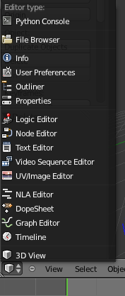 The window types that we are most interested in right
now are:
The window types that we are most interested in right
now are:- File Browsers- comes up automatically on demand in most cases
- User Preferences- menus and options
- UV/Image Editor- for applying game textures
- Video Sequence Editor- for animations
- 3D View- to see our work and model items
The User Preferences Window
If you place your mouse on the line between the 3D window and the User Preferences window (at the top), hold down the Left Mouse Button (LMB) and drag down, you will expose a number of setting options at the top of the screen.
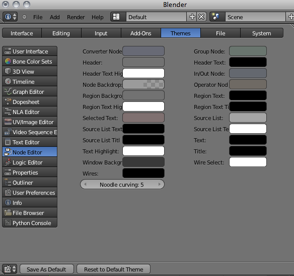
Settings of interest -
- Interface- tool tips and mouse settings
- Editing- how things are linked and duplicated
- Addons- how things are linked and duplicated
Save, Open, Append
Open/Append
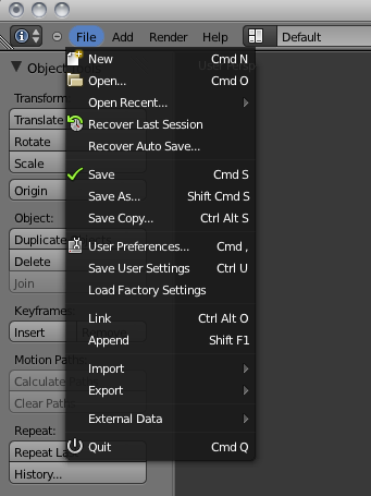 Blender utilizes commands similar
to other programs when it comes
to saving and opening your work
with a few exceptions. Other
programs use "import" and "insert"
commands to bring other files
together. Blender just uses Open
and Append. If you are bringing
elements in from another Blender
(.blend) file, you use Append. If
you are bringing other types of files
into Blender, you only need to use
the Open command and this will
insert the other file types into your
Blender file. Blender accepts
VRML (.wrl) and .DXF files into the
program.
The Save Command
With the old Blender it seemed almost impossible to figure out how to save your work. The file interface resembled old MS-DOS. The new interface is much more intuitive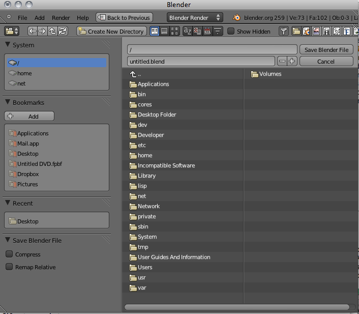
The Append Command
When you need to insert elements from one Blender (.blend) file into another one, you need to use the Append command from the file pull-down menu. While in Append, you need to navigate to the Blender file you wish to insert from, then select what you want to append into the open file. You can append anything from cameras, lights meshes, materials, textures, scenes and objects. For most purposes, use the Object option. By appending objects, any materials, textures and animations that are linked to that object will automatically come in with it. Right Mouse Button (RMB-⌘+click) clicking on objects will select/deselect them. Typing A will select them all. After you select all objects to append, click the Load Library button in the upper right corner of the screen.Packing Data
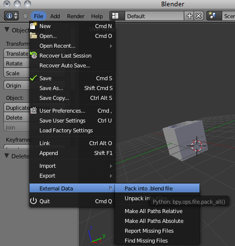 If you plan to open this file on other
computers, you will need to select the
Pack Data option in the file menu.
Textures and sounds are not
automatically included in your Blender
file in order to keep the file size down.
Every time your file opens, it looks for
the textures and sounds and places
them into your model. If it can't find
the files, you won't have any textures
and sounds. If you pack data, those
files are included with the .blend file
so they can be opened anywhere,
however, your file size may explode.
When data is packed, a small package
shows up on the top of your screen
letting you know that the file is packed.
You can also unpack data to bring the
file size back down.
Manipulators
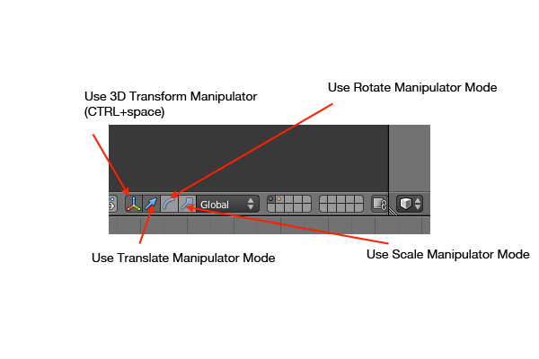
You can use the manipulators instead of the hotkeys to manipulate your objects.
Make sure you are in object mode and that the pivot mode is set to median point or bounding box center:
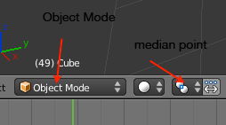
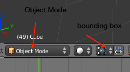
To move the object, hold the LMB on one of the arrows and drag in the direction you want your object to move in.
To use keyboard shortcuts:
G for move
R for rotate
S for scale
You can constrain the movement in specific directions by pressing X,Y or Z
Global X,Y and Z are world space. Z is always up, no matter which way the object is rotated. In local space, Z is up only in terms of the object itself.
To the right of the manipulator tool buttons is a drop-down list where you can change whether the manipulator arrows work on global or local coordinates. Changing between the two modes will change the direction of the arrows.
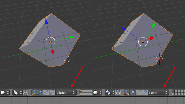
Press N to reveal the Properties Panel:

You can specify your transformations through numbers.
OPT+G resets the location to the global center
OPT+R resets the rotation so the object stands pright in global coordinates
OPT+S resets the scale to the object's original size
If you want to change an object's rested position, make the changes, then lock in its new positioning by selecting Object>Apply>Location/Rotation/Scale from the bottom menu.
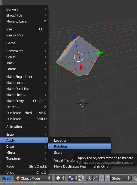
Typical Views
