FreeCad
FreeCAD is an amazing program, and this introduction will barely touch on all that you are capable of accomplishing with it. FreeCAD is a general all-purpose 3D modeling application. The interface is divided into a series of
Workbenches, which allows you to change the interface contents to display all or only the tools necessary for your specific task, or group of tasks.
Think of the interface as a container, with a menu bar, a 3D view area, and side panels for displaying the scene contents or object properties. All the contents of these panels can also be modified depending on the workbench.
When you first open the application, you will see the
general workbench, or the
complete workbench. The
complete workbench is very handy for discovering FreeCAD more easily.
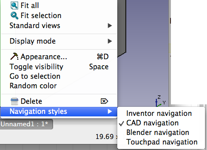
The default
Navigation is
CAD Navigation, where navigating the space is similar to other CAD programs, with the exception of rotating. Left mouse click lets you select the object. Holding CTRL lets you add to the selection. The middle mouse allows you to pan and zoom. To rotate, hold the middle mouse button down then add the left mouse down then drag to rotate.
You can also CTRL click to select a view from the context menu:
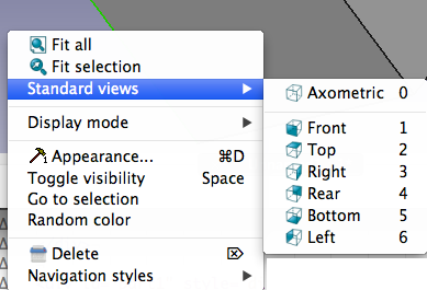
You can also select
Inventor Navigation. Here to select an object hold CTRL+LEFT mouse click. Click the left mouse button to move the object around. Zoom in and out with the scroll wheel or hold the middle mouse button then click the left mouse button. Click and drag with the left mouse button to rotate
The third navigation object is
Blender Navigation. Left mouse button to select an object. Hold shift and click the middle mouse button to pan. Mouse wheel to zoom. Click and drag with the middle mouse button to rotate.
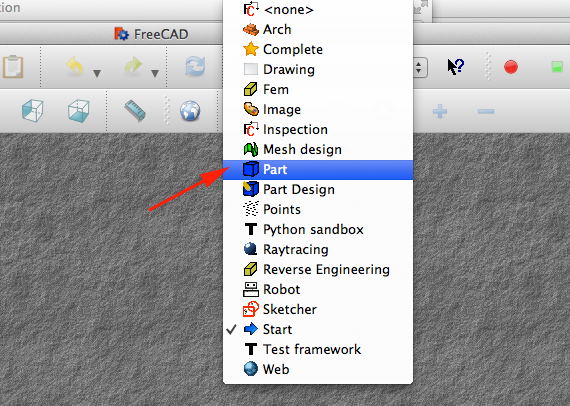
Part Module
- Download FreeCad and install
- Select the Part Module from the Start dropdown menu at the top
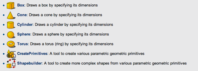
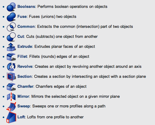
Here are the tools associated with the Part Module Workbench
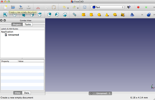
- Select a New Empty Document

- This is the new view:
- The Part Workbench uses solid modeling. You work with primitive shapes like cubes, cylinders, spheres and cones to construct your geometry by combining them, subtracting one shape from the other, or intersecting them. You can also apply transformations on shapes, like applying rounds or chamfers on edges. These tools are also in the Part Workbench.
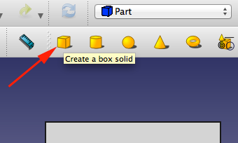
Click on the Box Button
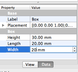
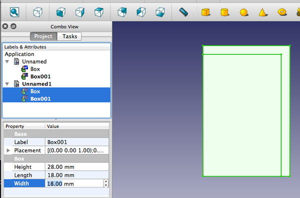
- You can change the dimensions by selecting it either in the 3D space, or by clicking it in the Project tab to the left, then
Click on the Data tab at the bottom, and change values for Height, Length and Width to 30mm, 20 and 20
- To see the changes you can rotate the cube. Hold down the center button, then add the left and drag to rotate.
-
- Create a second box the same way, but with values 28, 18 and 18mm. By default this box will be superimposed on the first one.

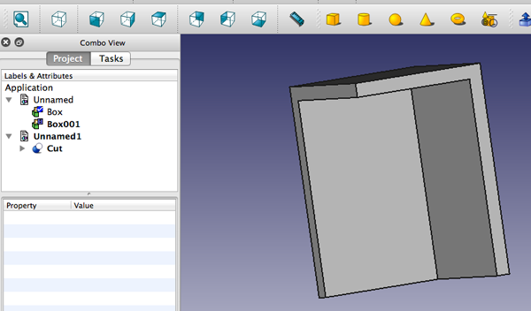
- You'll now subtract the second box from the first. Select the first shape first (named Box), then the second one (named Box001), the selection order is important!
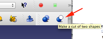
- On the Part Workbench toolbar, click on the Cut tool
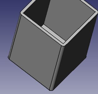
- Rotate to see the Boolean difference
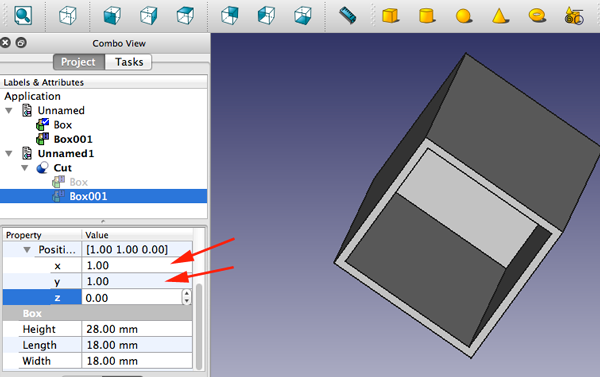
- You can toggle open the cut, select one of the boxes and make modifications to the properties.
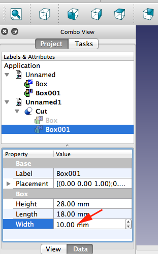
- Want the cut from the center, adjust the position
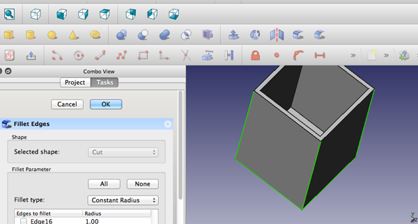
- To add a fillet, select the fillet tool, click the appropriate edges and press the OK button
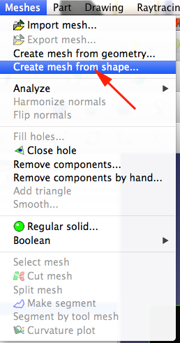
- To be able to print the form you'll have to convert it to a mesh and then export it:
- Once it is a mesh, you can analyze it:
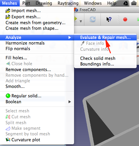
- Then you can export as an stl

New York State Learning Standards
Mathematics, Science, and Technology
-
STANDARD 1
Analysis, Inquiry, and Design: ENGINEERING DESIGN
Key Idea 1: details
Engineering design is an iterative process involving modeling and optimization (finding the best solution within given constraints); this process is used to develop technological solutions to problems within given constraints. (Note: The design process could apply to activities from simple investigations to long-term projects.)
Elementary
| 1.1 | Describe objects, imaginary or real, that might be modeled or made differently and suggest ways in which the objects can be changed, fixed, or improved | |
| 1.2 | Investigate prior solutions and ideas from books, magazines, family, friends, neighbors, and community members | |
| 1.3 | Generate ideas for possible solutions, individually and through group activity; apply age-appropriate mathematics and science skills; evaluate the ideas and determine the best solution; and explain reasons for the choices | |
| 1.4 | Plan and build, under supervision, a model of the solution using familiar materials, processes, and hand tools | |
| 1.5 | Discuss how best to test the solution; perform the test under teacher supervision; record and portray results through numerical and graphic means; discuss orally why things worked or didn't work; and summarize results in writing, suggesting ways to make the solution better | |
Intermediate
| T1.1 | Identify needs and opportunities for technical solutions from an investigation of situations of general or social interest. | |
| T1.1a | Identify a scientific or human need that is subject to a technological solution which applies scientific principles | √ |
| T1.2 | Locate and utilize a range of printed, electronic, and human information resources to obtain ideas. | √ |
| T1.2a | Use all available information systems for a preliminary search that addresses the need. | √ |
| T1.3 | Consider constraints and generate several ideas for alternative solutions, using group and individual ideation techniques (group discussion, brainstorming, forced connections, role play); defer judgment until a number of ideas have been generated; evaluate (critique) ideas; and explain why the chosen solution is optimal. | √ |
| T1.3a | Generate ideas for alternative solutions | √ |
| T1.3b | Evaluate alternatives based on the constraints of design | √ |
| T1.4 | Develop plans, including drawings with measurements and details of construction, and construct a model of the solution, exhibiting a degree of craftsmanship. | √ |
| T1.4a | Design and construct a model of the product or process | √ |
| T1.4b | Construct a model of the product or process | √ |
|
T1.5 | In a group setting, test their solution against design specifications, present and evaluate results, describe how the solution might have been modified for different or better results, and discuss trade-offs that might have to be made. | √ |
| T1.5a | Test a design | √ |
| T1.5b | Evaluate a design | √ |
Commencement
| 1.1 | Initiate and carry out a thorough investigation of an unfamiliar situation and identify needs and opportunities for technological invention or innovation | |
| 1.2 | identify, locate, and use a wide range of information resources including subject experts, library references, magazines, videotapes, films, electronic data bases and online services, and discuss and document through notes and sketches how findings relate to the problem | |
| 1.3 | generate creative solution ideas, break ideas into the significant functional elements, and explore possible refinements; predict possible outcomes using mathematical and functional modeling techniques; choose the optimal solution to the problem, clearly documenting ideas against design criteria and constraints; and explain how human values, economics, ergonomics, and environmental considerations have influenced the solution | |
| 1.4 | develop work schedules and plans which include optimal use and cost of materials, processes, time, and expertise; construct a model of the solution, incorporating developmental modifications while working to a high degree of quality (craftsmanship) | |
| 1.5 | in a group setting, devise a test of the solution relative to the design criteria and perform the test; record, portray, and logically evaluate performance test results through quanitative, graphic, and verbal means; and use a variety of creative verbal and graphic techniques effectively and persuasively to present conclusions, predict impacts and new problems, and suggest and pursue modifications | |
-
STANDARD 2
INFORMATION SYSTEMS
Key Idea 1: details
Information technology is used to retrieve, process, and communicate information as a tool to enhance learning.
Elementary
| 1.1 | Use computer technology,traditional paper-based resources,and interpersonal discussions to learn, do, and share science in the classroom | √ |
| 1.2 | Select appropriate hardware and software that aids in wordprocessing, creating databases, telecommunications, graphing, data display, and other tasks | √ |
| 1.3 | Use information technology to link the classroom to world events | |
Intermediate
| 1.1 | Use a range of equipment and software to integrate several forms of information in
order to create good-quality audio, video, graphic, and text-based presentations. | |
| 1.2 | Use spreadsheets and database software to collect, process, display, and analyze information. Students access needed information from electronic databases and on-line telecommunication services. | |
| 1.3 | Systematically obtain accurate and relevant information pertaining to a particular topic from a range of sources, including local and national media, libraries, muse- ums, governmental agencies, industries, and individuals. | |
| 1.4 | Collect data from probes to measure events and phenomena. | |
| 1.4a | Collect the data, using the appropriate, available tool | |
| 1.4b | Organize the data | |
| 1.4c | Use the collected data to communicate a scientific concept | √ |
| 1.5 | Use simple modeling programs to make predictions. | |
Physics
| 1.1 | Understand and use the more advanced features of word processing, spreadsheets,
and database software. | |
| 1.2 | Prepare multimedia presentations demonstrating a clear sense of audience and
purpose. (Note: Multimedia may include posters, slides, images, presentation software, etc.) | √ |
| 1.2a | Extend knowledge of physical phenomena through independent investigation,
e.g., literature review, electronic resources, library research | |
| 1.2b | Use appropriate technology to gather experimental data, develop models,and
present results | √ |
| 1.3 | Access, select, collate, and analyze information obtained from a wide range of
sources such as research databases, foundations, organizations, national libraries, and electronic communication networks, including the Internet. | |
| 1.3a | Use knowledge of physics to evaluate articles in the popular press on
contemporary scientific topics | |
| 1.4 | Utilize electronic networks to share information. | √ |
| 1.5 | Model solutions to a range of problems in mathematics, science, and technology, using computer simulation software. | √ |
| 1.5a | Use software to model and extend classroom and laboratory experiences,recognizing the differences between the model used for understanding and real-world behavior | √ |
-
STANDARD 5
Technology: Engineering Design
Key Idea 1:
(See Standard 1:ENGINEERING DESIGN)
-
STANDARD 5
Technology: Computer Technology
Key Idea 3: details
Computers, as tools for design, modeling, information processing, communication, and system control, have greatly increased human productivity and knowledge.
Elementary
| 3.1 | Identify and describe the function of the major
components of a computer system. | |
| 3.2 | Use the computer as a tool for generating and drawing
ideas. | √ |
| 3.3 | Control computerized devices and systems through
programming. | √ |
| 3.4 | Model and simulate the design of a complex environment
by giving direct commands. | √ |
Intermediate
| 3.1 | Assemble a computer system including keyboard, central processing unit and disc drives, mouse, modem, printer, and monitor | |
| 3.2 | Use a computer system to connect to and access needed information from various Internet sites | √ |
| 3.3 | Use computer hardware and software to draw and dimension prototypical designs | √ |
| 3.4 | Use a computer as a modeling tool | √ |
| 3.5 | Use a computer system to monitor and control external events and/or systems | √ |
Commencement
| 3.1 | Understand basic computer architecture and describe the function of computer subsystems and peripheral devices | |
| 3.2 | Select a computer system that meets personal needs | |
| 3.3 | Attach a modem to a computer system and telephone line, set up and use communications software, connect to various online networks, including the Internet, and access needed information using email, telnet, gopher, ftp, and web searches | √ |
| 3.4 | Use computer-aided drawing and design (CADD) software to model realistic solutions to design problems | √ |
| 3.5 | Develop an understanding of computer programming and attain some facility in writing computer programs | √ |
-
STANDARD 5
Technology: Technological Systems
Key Idea 4: details
Technological systems are designed to achieve specific results and produce outputs, such as products, structures, services, energy, or other systems.
Elementary
| 4.1 | Identify familiar examples of technological systems that
are used to satisfy human needs and wants, and select
them on the basis of safety, cost, and function. | |
| 4.2 | Assemble and operate simple technological systems,
including those with interconnecting mechanisms to
achieve different kinds of movement. | |
| 4.3 | Understand that larger systems are made up of smaller
component subsystems. | |
Intermediate
| 4.1 | Select appropriate technological systems on the basis of safety, function, cost, ease of operation, and quality of post-purchase support | |
| 4.2 | Assemble, operate, and explain the operation of simple open- and closed-loop electrical, electronic, mechanical, and pneumatic systems | |
| 4.3 | Describe how subsystems and system elements (inputs, processes, outputs) interact within systems | |
| 4.4 | Describe how system control requires sensing information, processing it, and making changes | √ |
Commencement
| 4.1 | Explain why making tradeoffs among characteristics, such as safety, function, cost, ease of operation, quality of post-purchase support, and environmental impact, is necessary when selecting systems for specific purposes | |
| 4.2 | Model, explain, and analyze the performance of a feedback control system | |
| 4.3 | Explain how complex technological systems involve the confluence of numerous other systems | |
-
STANDARD 6
Interconnectedness: Common Themes
SYSTEMS THINKING:
Key Idea 1: details
Through systems thinking, people can recognize the commonalities that exist among all systems and how parts of a system interrelate and combine to perform specific functions.
Elementary
| 1.1 | Observe and describe interactions among components of
simple systems. | √ |
| 1.2 | Identify common things that can be considered to be
systems (e.g., a plant population, a subway system, human beings). | |
Intermediate
| 1.1 | Describe the differences between dynamic systems and
organizational systems. | |
| 1.2 | describe the differences and similarities between
engineering systems, natural systems, and social systems. | |
| 1.3 | Describe the differences between open- and closed-loop
systems. | |
| 1.4 | Describe how the output from one part of a system
(which can include material, energy, or information) can become the input to other parts. | |
Commencement
| 1.1 | Explain how positive feedback and negative feedback
have opposite effects on system outputs. | |
| 1.2 | Use an input-process-output-feedback diagram to model
and compare the behavior of natural and engineered
systems. | |
| 1.3 | Define boundary conditions when doing systems analysis to determine what
influences a system and how it behaves. | |
-
STANDARD 6
Interconnectedness: Common Themes
MODELS:
Key Idea 2: details
Models are simplified representations of objects, structures, or systems used in analysis, explanation, interpretation, or design.
Elementary
| 2.1 | Analyze,construct,and operate models in order to discover attributes of the real thing | √ |
| 2.2 | Discover that a model of something is different from the real thing but can be used to study the real thing
| √ |
| 2.3 | Use different types of models, such as graphs,sketches,diagrams,and maps,to represent various aspects of the real world | |
Intermediate
| 2.1 | Select an appropriate model to begin the search for answers or solutions to a question or problem. | |
| 2.2 | Use models to study processes that cannot be studied directly (e.g., when the real
process is too slow, too fast, or too dangerous for direct observation).
| √ |
| 2.3 | Demonstrate the effectiveness of different models to represent the same thing and
the same model to represent different things. | |
Physics
| 2.1 | Revise a model to create a more complete or improved representation of the
system. | |
| 2.2 | Collect information about the behavior of a system and use modeling tools to
represent the operation of the system.
| √ |
| 2.2a | Use observations of the behavior of a system to develop a model | |
| 2.3 | Find and use mathematical models that behave in the same manner as the
processes under investigation. | |
| 2.3a | Represent the behavior of real-world systems,using physical and mathematical
models | √ |
| 2.4 | Compare predictions to actual observations, using test models.
| √ |
| 2.4a | Validate or reject a model based on collated experimental data | √ |
| 2.4b | Predict the behavior of a system,using a model | √ |
-
STANDARD 7
Interdisciplinary Problem Solving
STRATEGIES:
Key Idea 2: details
Solving interdisciplinary problems involves a variety of skills and strategies, including effective work habits; gathering and processing information; generating and analyzing ideas; realizing ideas; making connections among the common themes of mathematics, science, and technology; and presenting results.
Physics
| 2.1 | Collect,analyze,interpret,and present data,using appropriate tools | √ |
| 2.2 | When students participate in an extended,culminating mathematics,science,and
technology project, then students should: |
| | Work effectively—Contributing to the work of a brainstorming group, laboratory partnership, cooperative learning group, or project team; planning procedures; identify and managing responsibilities of team members; and staying on task, whether working alone or as part of a group.
| √ |
| | Gather and process information —Accessing information from printed media, electronic data bases, and community resources and using the information to develop a definition of the problem and to research possible solutions. | √ |
| | Generate and analyze ideas — Developing ideas for proposed solutions, investigating ideas, collecting data, and showing relationships and patterns in the data. | √ |
| | Observe common themes—Observing examples of common unifying themes, applying them to the problem, and using them to better understand the dimensions of the problem. | √ |
| | Realize ideas—Constructing components or models, arriving at a solution, and evaluating the result.
| √ |
| | Present results—Using a variety of media to present the solution and to communicate the results. | √ |
CDOS
Standard 2: Integrated Learning
details
Students will demonstrate how academic knowledge and skills are applied in the workplace and other settings.
Integrated learning encourages students to use essential academic concepts, facts, and procedures in applications related to life skills and the world of work. This approach allows students to see the usefulness of the concepts that they are being asked to learn and to understand their potential application in the world of work.
Elementary
| 2.1 | Identify academic knowledge and skills that are required
in specific occupations | |
| 2.2 | Demonstrate the difference between the knowledge of a
skill and the ability to use the skill | √ |
| 2.3 | Solve problems that call for applying academic
knowledge and skills. | √ |
Intermediate
| 2.1 | Apply academic knowledge and skills using an interdisciplinary approach to demonstrate the relevance of how these skills are applied in work-related situations in local, state, national, and international communities | |
| 2.2 | Solve problems that call for applying academic knowledge and skills | √ |
| 2.3 | Use academic knowledge and skills in an occupational context, and demonstrate the application of these skills by using a variety of communication techniques (e.g., sign language, pictures, videos, reports, and technology). | |
Commencement
| 2.1 | Demonstrate the integration and application of academic
and occupational skills in their school learning, work,
and personal lives. | |
| 2.2 | Use academic knowledge and skills in an occupational
context, and demonstrate the application of these skills by using a variety of communication techniques (e.g., sign language, pictures, videos, reports, and technology) | |
| 2.3 | Research, interpret, analyze, and evaluate information and experiences as related to academic knowledge and technical skills when completing a career plan. | |
Standard 3a: Universal Foundation Skills
details
Students will demonstrate mastery of the foundation skills and competencies essential for success in the workplace.
Thinking skills
Thinking skills lead to problem solving, experimenting, and focused observation and allow the application of knowledge to new and unfamiliar situations.
Elementary
| 3.2.1 | Use ideas and information to make decisions and solve
problems related to accomplishing a task.
| √ |
Intermediate
| 3.2.1 | Evaluate facts, solve advanced problems, and make
decisions by applying logic and reasoning skills.
| √ |
Commencement
| 3.2.1 | Demonstrate the ability to organize and process
information and apply skills in new ways.
| √ |
- Technology
Technology is the process and product of human skill and ingenuity in designing and creating things from available resources to satisfy personal and societal needs and wants.
Elementary
| 3.5.1 | Demonstrate an awareness of the different types of
technology available to them and of how technology affects society.
| |
Intermediate
| 3.5.1 | Select and use appropriate technology to complete a task.
| √ |
Commencement
| 3.5.1 | Apply their knowledge of technology to identify and solve
problems.
| √ |
- Managing Resources
Using resources includes the application of financial and human factors, and the elements of time and materials to successfully carry out a planned activity.
Elementary
| 3.7.1 | Demonstrate an awareness of the knowledge, skills,
abilities, and resources needed to complete a task.
| √ |
Intermediate
| 3.7.1 | Understand the material, human, and financial resources
needed to accomplish tasks and activities.
| √ |
Commencement
| 3.7.1 | Allocate resources to complete a task.
| √ |
- Systems
Systems skills include the understanding of and ability to work within natural and constructed systems.
Elementary
| 3.8.1 | Demonstrate understanding of how a system operates
and identify where to obtain information and resources within the system.
| √ |
Intermediate
| 3.8.1 | Understand the process of evaluating and modifying
systems within an organization.
| √ |
Commencement
| 3.8.1 | Demonstrate an understanding of how systems
performance relates to the goals, resources, and functions of an organization.
| √ |
Standard 3b: Career Majors
details
Students who choose a career major will acquire the career-specific technical knowledge/skills necessary to progress toward gainful employment, career advancement, and success in postsecondary programs.
- Engineering/Technologies
Core, Specialized and Experiential
| 3b.1 | Foundation Development—Develop practical understanding of engineering
technology through reading, writing, sample problem solving, and employment experiences.
| |
| 3b.2 | Technology—Demonstrate how all types of engineering/technical
organizations, equipment (hardware/software), and well-trained human resources assist and expedite the production/distribution of goods and services
| |
| 3b.3 | Engineering/Industrial Processes—Demonstrate knowledge of planning, product
development and utilization, and evaluation that meets the needs of industry.
| |
