/ / Introduction
The capSense library turns two or more 'duino pins into a capacitive sensor, which can sense the electrical capacitance of the human body. All the sensor setup requires is a medium to high value resistor and a piece of wire and a small (to large) piece of aluminum foil on the end. At its most sensitive, the sensor will start to sense a hand or body inches away from the sensor.
The current version of the library (03) has been updated to C++ and supports multiple inputs. It also includes some utility functions to make it convenient to change timeout values.
Applications
Capacitive sensing may be used in any place where low to no force human touch sensing is desirable. A 'duino and the library may be used to sense human touch through more than a quarter of an inch of plastic, wood, ceramic or other insulating material (not any kind of metal though), enabling the sensor to be completely visually concealed.
A capacitive sensor covered with paper or other insulator also acts as fairly good (human touch) pressure sensor with an approximately logarithmic response. In this regard it may surpass force sensing resistors in some applications.
How it works
The capSense method toggles a microcontroller send pin to a new state and then waits for the receive pin to change to the same state as the send pin. A variable is incremented inside a while loop to time the receive pin's state change. The method then reports the variable's value, which is in arbitrary units.
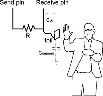
The physical setup includes a medium to high value (100K - 50M) resistor between the send pin and the receive (sensor) pin. The receive pin is the sensor terminal. A wire connected to this pin with a piece of foil at the end makes a good sensor. For many applications, a more useful range of values is obtained if the sensor is covered with paper, plastic, or another insulating material, so that users do not actually touch the metal foil.
When the send pin changes state, it will eventually change the state of the receive pin. The delay between the send pin changing and the receive pin changing is determined by an RC time constant, defined by R * C, where R is the value of the resistor and C is the capacitance at the receive pin, plus any other capacitance (e.g. human body interaction) present at the sensor (receive) pin.
Library Methods
The library contains three main methods and some utility methods:
CapSense CapSense(byte sendPin, byte receivePin)
CapSense creates an instance of the library (please note the capital letters, this is not the same method as below)
long capSenseRaw(byte samples)
capSenseRaw requires one parameter, samples, and returns a long containing the absolute capacitance, in arbitrary units. The samples parameter can be used to increase the returned resolution, at the expense of slower performance. The returned value is not averaged over the number of samples, and the total value is reported.
capSenseRaw will return -2 if the capacitance value exceeds the value of CS_Timeout_Millis (in milliseconds).
The default value for CS_Timeout_Millis 2000 milliseconds (2 seconds).
long capSense(byte samples)
capSense requires one parameter, samples, and returns a long containing the added (sensed) capacitance, in arbitrary units. capSense keeps track of the lowest baseline (unsensed) capacitance, and subtracts that from the sensed capacitance, so it should report a low value in the unsensed condition.
The baseline is value is re-calibrated at intervals determined by CS_Autocal_Millis. The default value is 200000 milliseconds (20 seconds). This re-calibration may be turned off by setting CS_Autocal_Millis to a high value with the set_CS_AutocaL_Millis() method.
void set_CS_Timeout_Millis(unsigned long timeout_millis);
The set_CS_Timeout_Millis method may be used to set the CS_Timeout_Millis value, which determines how long the method will take to timeout, if the receive (sense) pin fails to toggle in the same direction as the send pin. A timeout is neccessary because a while loop will lock-up a sketch unless a timeout is provided. CS_Timeout_Millis' default value is 2000 (2 seconds).
void reset_CS_AutoCal()
reset_CS_AutoCal may be used to force an immediate calibration of capSense function.
void set_CS_AutocaL_Millis(unsigned long autoCal_millis)
The method set_CS_AutocaL_Millis(unsigned long autoCal_millis) may be used to set the timeout interval of the capSense function. Re-calibration may be turned off by using set_CS_AutocaL_Millis to set CS_AutocaL_Millis to "0xFFFFFFFF".
Resistor Choice
Here are some guidelines for resistors but be sure to experiment for a desired response.
- Use a 1 M (megohm) resistor (or less maybe) for absolute touch to activate.
- With a 10 M resistor the sensor will start to respond 4-6 inches away.
- With a 40 M resistor the sensor will start to respond 12-24 inches away (dependent on the foil size). Common resistor sizes usually end at 10Meg so you may have to solder four 10M resistors end to end.
The only tradeoff with larger resistors is that the sensor's increased sensitivity means that it is slower. Also if the sensor is exposed metal, it is possible that the send pin will never be able to force a change in the receive (sensor) pin, and the sensor will timeout.
Note that the hardware can be set up with one sPin and several resistors and rPin's for calls to various capacitive sensors. See the example sketch.
Grounding and other known issues
The grounding of the 'duino board is very important in capacitive sensing. The board needs to have some connection to ground, even if this is not a low-impedance path such as a wire attached to a water pipe.
Capacitive sensing has some quirks with laptops unconnected to mains power. The laptop itself tends to become sensitive and bringing a hand near the laptop will change the returned values.
Connecting the charging cord to the laptop will usually be enough to get things working correctly. Connecting the arduino ground to an earth ground (e.g.water pipe) could be another solution.
Another solution that seems to have worked well on at least one installation, is to run a foil ground plane under the sensor foil (insulated by plastic, paper etc), and connected by a wire to ground. This worked really well to stabilize sensor values and also seemed to dramatically increase sensor sensitivity.
Scroll Wheels (well, slide pots anyway)
Experiments with a slide pot type linear sensor have been successful with just two pins and a resistance ladder. The basic layout is shown in the Quantum Scrollwheel sensor datasheet.
The code uses this type of arrangement
CapSense Left32  = CapSense(3, 2); // wire from pin 2 to left side of resistor ladder\
CapSense Right23 = CapSense(2, 3); // wire from pin 3 to right side of resistor ladder
Where the pins switch their send and receive positions. With a linear resistance ladder, a finger closer to the send pin will report lower values because resistance downstream from the capacitance is basically out of the circuit.
So in this manner when a finger is moved from one pin to the other the two calls to capSenseRaw will report complementary values that have an approximately constant value to them. The complication comes in when trying to deal with how much contact (capacitance) is present, which raises (or lowers) both values, but not necessarily in a linear manner.
At some point I'll get the sketch posted here.
Error Messages
capSense and capSenseRaw will return -1 with an invalid choice of pin parameter, but it appears that this feature is not working at this writing. Engineers are working on this, stand by...
capSense and capSenseRaw will return -2 if the methods timeout. This is caused by the count exceeding the value of CS_Timeout_Millis, which is set at a default value of 2000 milliseconds (2 seconds). This is most often caused by a missing resistor or the resistor in the wrong pin. It could also be caused by a sensor that is grounded or connected to +5V.
A timeout is necessary because the while loop that does the timing in the CapSense method, will lock-up the sketch (the function will never return) if, for example, the resistor between sendPin and receivePin becomes disconnected.
Installation
- Download CapacitiveSense003.zip
- Unzip, and add to Arduino/hardware/libraries/
- To add capSense to a new sketch choose Sketch->Import Library->CapSense
Demo Sketch
#include <CapSense.h>

/*
 * CapitiveSense Library Demo Sketch
 * Paul Badger 2008
 * Uses a high value resistor e.g. 10M between send pin and receive pin
 * Resistor effects sensitivity, experiment with values, 50K - 50M. Larger resistor values yield larger sensor values.
 * Receive pin is the sensor pin - try different amounts of foil/metal on this pin
 * Best results are obtained if sensor foil and wire is covered with an insulator such as paper or plastic sheet
 */


CapSense   cs_4_2 = CapSense(4,2);        // 10M resistor between pins 4 & 2, pin 2 is sensor pin, add wire, foil
CapSense   cs_4_5 = CapSense(4,5);        // 10M resistor between pins 4 & 6, pin 6 is sensor pin, add wire, foil
CapSense   cs_4_8 = CapSense(4,8);        // 10M resistor between pins 4 & 8, pin 8 is sensor pin, add wire, foil

void setup()
{

   cs_4_2.set_CS_AutocaL_Millis(0xFFFFFFFF);     // turn off autocalibrate on channel 1 - just as an example
   Serial.begin(9600);

}

void loop()
{
    long start = millis();
    long total1 =  cs_4_2.capSense(30);
    long total2 =  cs_4_5.capSense(30);
    long total3 =  cs_4_8.capSense(30);

    Serial.print(millis() - start);        // check on performance in milliseconds
    Serial.print("\t");                    // tab character for debug windown spacing

    Serial.print(total1);                  // print sensor output 1
    Serial.print("\t");
    Serial.print(total2);                  // print sensor output 2
    Serial.print("\t");
    Serial.println(total3);                // print sensor output 3

    delay(10);                             // arbitrary delay to limit data to serial port
}
Adafruit boards
This breakout board is the simplest way to create a project with mutiple capacitive touch sensors. No microcontroller is required here - just power with 1.8 to 5.5VDC and connect up to 5 conductive pads to the 5 left-hand pins. When a capacitive load is detected (e.g. a person touches one of the conductive contacts) the corresponding LED on the right lights up and the output pin goes low. You can use this to update an existing normal-button project where buttons connect to ground when pressed.
Note that only one contact will be detected at once (this is to protect against having a hand brush against two or more contacts at once.
Comes with a fully assembled board, and a stick of 0.1" header so you can plug it into a breadboard. For contacts, we suggest using copper foil, then solder a wire that connects from the foil pad to the breakout.
Standalone Toggle Capacitive Touch Sensor Breakout
The Toggle version of the sensor turns on when you touch it once, then turns off when you touch it again. The on-board LED indicates the state of the switch.
Adafruit 12-Key Capacitive Touch Sensor Breakout - MPR121
Add lots of touch sensors to your next microcontroller project with this easy-to-use 12-channel capacitive touch sensor breakout board, starring the MPR121. This chip can handle up to 12 individual touch pads.
The MPR121 has sup
port for only I2C, which can be implemented with nearly any microcontroller. You can select one of 4 addresses with the ADDR pin, for a total of 48 capacitive touch pads on one I2C 2-wire bus. Using this chip is a lot easier than doing the capacitive sensing with analog inputs: it handles all the filtering for you and can be configured for more/less sensitivity.
This sensor comes as a tiny hard-to-solder chip so we put it onto a breakout board for you. Since it's a 3V-only chip, we added a 3V regulator and I2C level shifting so its safe to use with any 3V or 5V microcontroller/processor like Arduino. We even added an LED onto the IRQ line so it will blink when touches are detected, making debugging by sight a bit easier on you. Comes with a fully assembled board, and a stick of 0.1" header so you can plug it into a breadboard. For contacts, we suggest using copper foil or pyralux, then solder a wire that connects from the foil pad to the breakout.
Standalone Momentary Capacitive Touch Sensor BreakoutThe momentary touch sensor works just like a momentary switch. It is on when you touch it and off when you move away. The on-board LED indicates the state of the switch.
For more information see
Adafruit's PDF
/ / Old chips
QT113
The QT113 is a capacitive touch sensor that operates like a switch.
Here are the parts you will need:
- QT113 touch sensor
- one Board
- one 8 pin socket
- one polarized 1uf capacitor
- arduino code sample
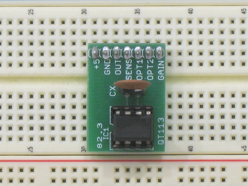
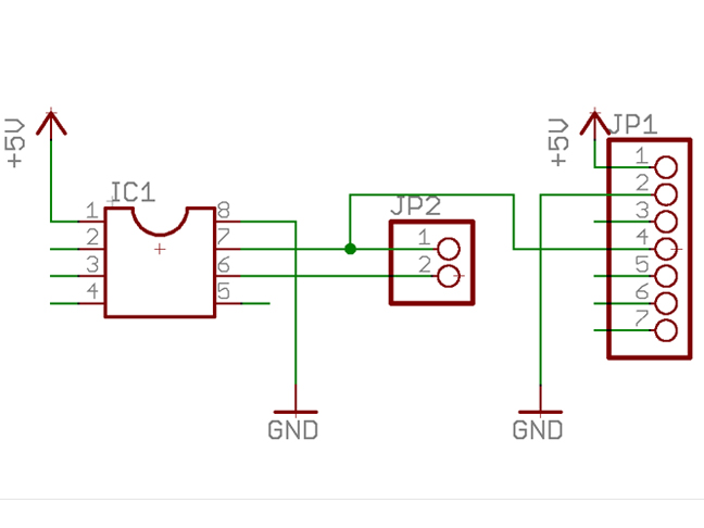
The QT113 is a touch sensor. From the pin labeled OUT, the QT113 sends a digital HIGH when a touch is detected and a digital LOW when there is none. The OUT pin is connected to an input pin on a microprocessor.
The SENS pin is the input. For testing, a simple wire can be used on this pin. Later when the application is fully realized, Other materials can be used. Copper mesh, metal plates, and conductive fabric are examples. Just about aby conductive material connected to the SENS pin will become part of the sensor.
there are two OPT pins OPT1 and OPT2. These option pins, when set to a combination of power and ground, determine the behavior of the output signal.
The following chart described the behavior of the sensor. The MAX on duration refers to the amount of time the sensor stays active once touched
- OPT1 OPT2 MAX on duration
- pwr pwr 10 sec
- pwr Gnd 60 sec
- Gnd Gnd Toggle
- Gnd pwr infinite
The GAIN pin sets the sensitivity with a digital HIGH or LOW depending on preference.
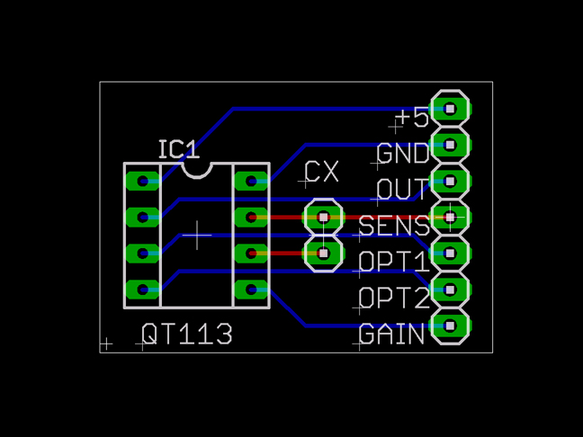
In examining the board, notice the pads labeled CX. This is for a .1uf ceramic disk capacitor. The capacitor can be switched with other values depending on your situation. The more capacitance, the more sensitive it will be. We are using female headers here. They are acting as a socket so that we can swap out capacitors.
Pin description:
- +5 this is the logic supply for the chip, connected to a 5 volt power supply
- GND this is connected to ground
- OUT this is connected to a digital input on your micro controler
- SENS this is the sensor pin. Connect one end of a a wire to this pin for testing
- OPT1 this is an option pin - see above chart
- OPT2 this is an option pin - see above chart
- GAIN this is the gain, it has 2 settings, HIGH and LOW.
Projects a proximity field through the air or any insulator to detect near-proximity or touch, specifically
designed for human interfaces (panels, appliances, toys, or lighting controls).
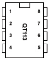
8-pin PDIP Integrated Circuit (IC)
- Power (2.45V – 5.25V)
- Out (To PIC)
- Option 1 (See Strap Option)
- Option 2 (See Strap Option)
- Gain (Changes Sensitivity)
- Electrode Connect 1
- Electrode Connect 2
- Ground
Schematic
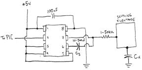
- A 100nF (0.1 uF) capacitor must be placed between Vdd & Vss (yes, power and ground)
for the IC to work properly.
- A capacitor (Cs) (10 – 500 nF) should be placed between Sns1 & Sns2.
- A resistor (1 – 50K?) should be placed between Sns2 & the electrode (sensor).
- Gain should be connected to power or ground (see Gain).
How it works
The IC continuously discharges ‘bursts’ storing voltage in Cs. As the electrode is touched,
voltage dumps from CS, which is recognized by the IC, sending a message through its ‘OUT’ pin.
Utilizes HeartBeat™ Output, a built-in feature that constantly checks for the ‘health’ of the IC
(this feature can be sampled by using a pull-down resistor on out & feeding the resulting
pulse to a counter).
Detection Integrator
The IC requires three (3) successive detections to create an output. This prevents an
accidental trigger by stray energy.
Timer
If a detection exceeds the timer setting, the timer forces a full recalibration. This allows for full functionality even if the conditions change (e.g., if something falls on the electrode).
Strap Option
These are read only on power up.
Note: Option pins should never be floating
DC Mode Output – active-low on detection, or until Max On-Duration expires
Toggle Mode Output – on/off mode (for power loads), fixed at 10s
Gain
Gain affects the sensor’s sensitivity. Connected to power (Vdd), sensitivity will increase. Sensitivity can also be increased by using a larger electrode or a larger capacitor (Cs). Likewise, sensitivity will decrease when gain is connected to ground (Vss), using a smaller electrode or a smaller capacitor (Cs).Remember, though, that increasing Cs decreases response time but increases resolution.
Experimentation will be helpful.
Electrode Design
There is no restriction to the design of the electrode, provided you use common sense.
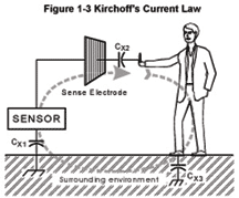
Kirchoff’s Current Law should be considered when creating your electrode. It states that a sensor’s field current must complete a loop, returning to its source for the capacitance to be sensed. Remember that the human body naturally has several picofarads of ‘free space’ capacitance to the local environment, which is two times more than needed. A field can be shaped by limiting it with ground wire (a grounded wire will prevent the
capacitance field from extending beyond it).
Questions
What does “>>” mean (as in "Cs >> Cx")???
It means Cs is an order of magnitude or more greater than Cx"
QT301
QT301 Capacitance to Analog Converter Data Report by Min Lee; Spring 2006
Min's ITP blog
QT113, 1 channel touch sensor, Datasheet Study
Touch lighting up the QT113
Toggle mode
movie demo
Analog QT301
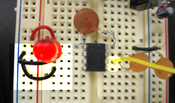
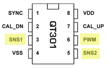
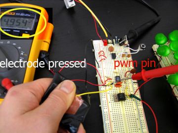
Unlike the QT113, the one-channel, touch sensor, the QT301 works off of the capacitance and outputs an analog signal. It has a PWM pin as oppsed to a digital OUT pin on the sensor.
Quantum Research's QT300 family QProx programmable capacitive ICs are suitable for touch, proximity, fluid, and material sensing.
What is it?
- The QT301 QProx™ programmable capacitive IC is suitable for fluid, and material sensing. It can project sense fields through up to 100mm (4”) of insulation or air. It is an 8-pin device available in SOIC or DIP.
- Its only output is raw, unprocessed data in filterable PWM form that can be translated into an analog voltage.
- PWM signal is a eight bits in resolution.
How is it different from other Touch Qprox sensors?
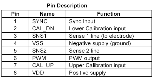
- Rescaleable PWM: PWM is set by two inputs that control the starting and the end point of the range. (Calibration pins) The PWM range can be optimized for the zone of interest for the user.
- Sync input is present to avoid external noise sources.
- Sensor's Internal Operation : QT301 has an EEPROM to store the two calibration points.
Basic Operations
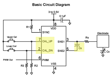
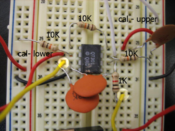
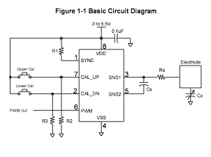
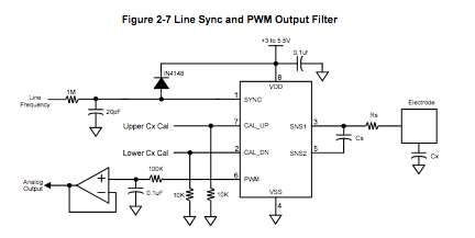
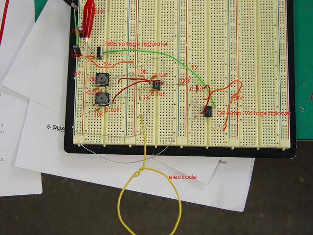
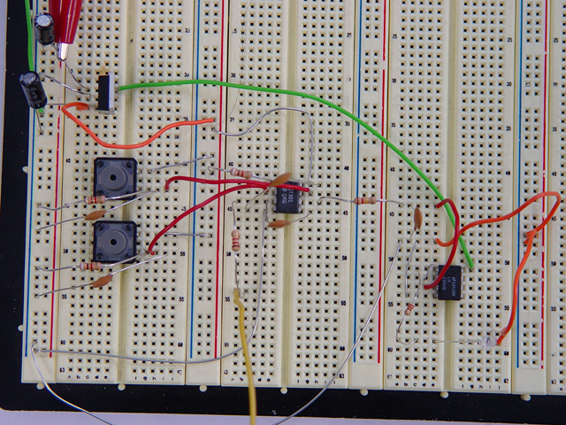
- In the circuit above, R1, R2, R3 are all 10K resistors and the C1 is 100nF.
- power-up delay of 300ms.
Cs/Cx Dependency
- The signal value depends directly on the Cs and Cx, where the Cs is the fixed capacitor, Cx is the unknown.
- The two values influence the sensitivity, resolution and response time of the electrode.
- Sensitivity and resolution are also a function of the size, shape and composition of the electrode.
PWM Output
- output is 100KHZ +- 7% square wave
- may not be 100% linear with changes in Cx
- during CAL, PWM output value is locked with the value just before the CAL process
Calibration
- CAL PINs are inputs used to trigger CAL process on the upper and lower Cx
- pins go through a pull down resistor to prevent damage (Note: NEVER BE driven low. will short circuit the chip)
- calibrated to have an effective properly scaled PWM output
- CAL_DN should be used to calibrate when the signal of the electrode is at its lowest
- CAL_UP should be used to calibrate when the signal of the electrode is at its max
- does not matter whether CAL_DN or CAL_UP are applied first
- after calibration, i can be calibrated again for adjustment
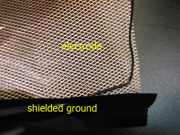
Like in the QT113, I found out that shielding the electrode with a ground around it gave it more focus for the part that was sensing.
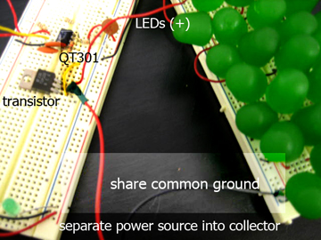
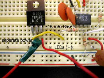
For my Living Art Project, I am using about 80 LEDs per candy jar to add movement and light to the LEDs. Hence, I attempted at trying to get as many LEDs to work off the PWM QT301 PIN. I had to go through a TIP120 transistor to be able to power all the 54 LEDs all at once to PWM according to the electrode off of the QT301.
/ / QT301
QT301 Touch Sensor
Sol HuhApril 18, 2006
I bought this QProx QT301 from DigiKey. Since
QT301 data sheet
Note: On VDD(8), 0.1nF capasitor is required. For Cs, 0.1nF capasitor is a good start before testing different size of capasitors.When Cs is small, the sensor gets more sensitive but unstable.
When calibrating, for the upper calibration, hold the electrode tight and connect the switch for 1 second. For lower calibration, do not touch the electrode and swtich on for a second.
I made a mistake understanding Cx at the begginning. I thought the CX is a distance of the electrode and finger when it is touched, but it was actually the distance between the finger and the electrode when it is not touched and it goes to the ground.
PWM & Low Pass Filter
Output of many chips is PWM because it can have similar output with analog in the digital IC.
For example, digital IC cannot get the 2.5V output. In this case, give the sign below.
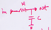
The average is 2.5. This averaging filter is low pass filter, also known as integrator.
Integrator adds the signal.
Cut Off frequency (Hz)=1/2pi *Rc = 100/2pi = 15Hz
QT301 has 100kHz which is much bigger than 15 Hz.
It cannot pass but it adds to the effective voltage.
Low voltage=0, high voltage=5, Average 2.5
Detail
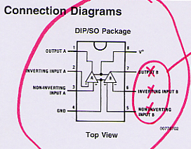
LM2904 Op Amp
Issue1. Electrode Design
How to control the detecting direction which goes every direction?
Experiment
Measure the amount of water in the cup.
The sensor must detect only water in the cup.
When I hold the cup, the sensor should not detect my hand.
How can I do?
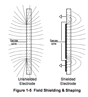
Reference from QT320
The electrode spread out its field to the all direction. Field must come out to the inside of the cup where the water is.
Place the sheilding material(metal) on the direction where the sensor should not detect. Then connect the metal to the ground.
I attatched the sheiding material(metal) to the outside of the cup and connected to the ground.
Planning
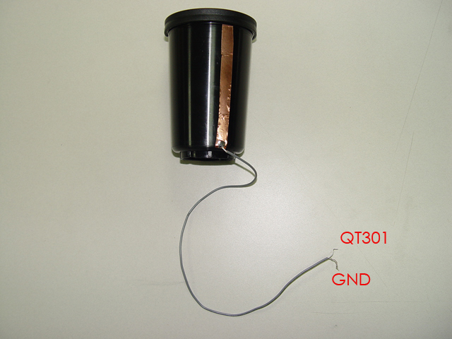 1. Coopper tape on the outside of the cup.
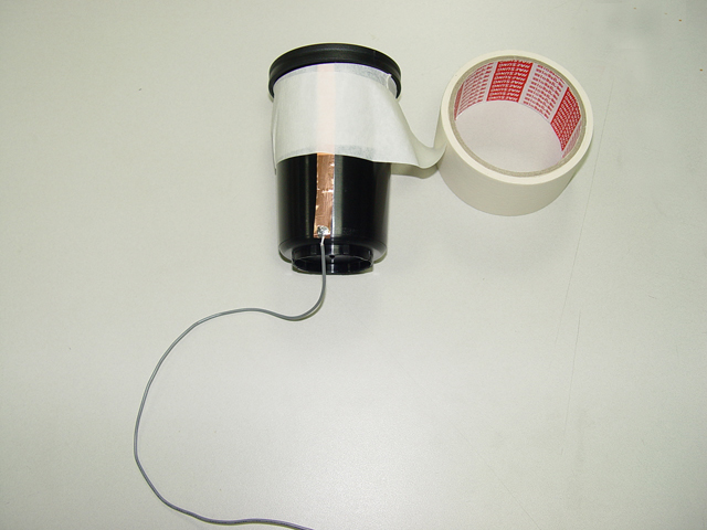 2. Wrapping up the paper tape
 3.
3.
 4. Surrounding metal is connected to the ground.
 5.
5.
Result
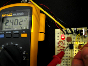
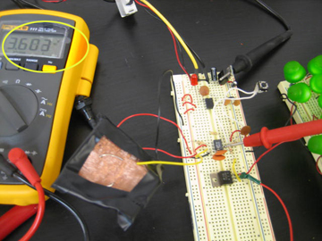
When the cup is full of water, voltage is 5V. When it is empty, the voltage is 0. The level of water and the voltage in between was unlinear.
Application for the other touch sensors
Systems using lower voltage is recommended t use QT118. It the voltage doesn't matter, using QT113 is recommended.
QT112: Fast responding use, such as a joystick for game machine.
QT113:Very sensitive When PCB is stable and voltage is 5, it senses about 3 inches. Voltage uses is 900uA , the highest.
QT115: In the several QT115 sensors, it can pass only the highest one signal by composing.
QT118: It has direct PIEZO connection pin. It's good for a battery using system.
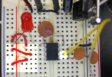
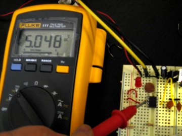



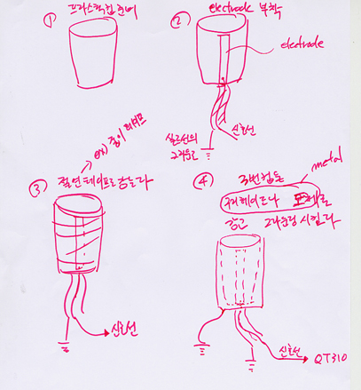
 1. Coopper tape on the outside of the cup.
 2. Wrapping up the paper tape
 3.
3. 4. Surrounding metal is connected to the ground.
 5.
5.