/ / Introduction
This synthesizer mixes two octaves together. The straight signal produced by the oscillator (CD4093) is pot A and is mixed with the tone one octave lower (pin 9 of the CD4040) and the two octaves lower(pin 7 of the CD4040).
/ / Parts
- CD4093 IC (Quad NAND Schmitt Trigger)
- CD4040 IC (12-bit Binary/Ripple Counter)
- One 14-pin socket
- One 16-pin socket
- One 0.1µF ceramic disk capacitor
- One 10µF electrolytic capacitor
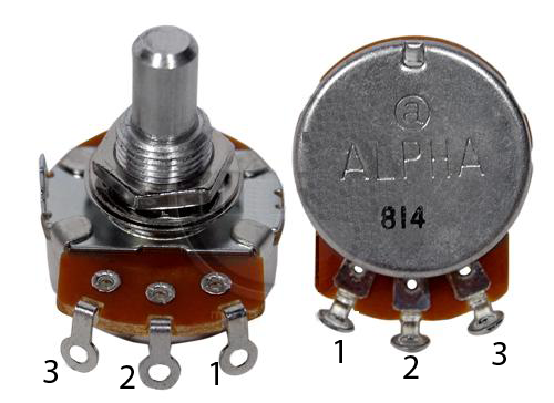
- One 100KΩ variable resistor (linear taper)
- Three 10KΩ variable resistor (audio taper)
- Four Control Knobs
- Three 10KΩ resistor (brown,black, brown)
- One 8Ω speaker
- One 470Ω resistor (yellow,purple, orange)
- One audio phone jack
- One Momentary Push Button
- 9 volt battery clip
- 9 volt battery
- hook-up wire
- Circuit Board
- Double sided foam tape
- Cigar box
/ / Instructions

- Insert the 14 pin IC socket into the top of the protoboard

- Insert the 16 pin IC socket into the bottom of the protoboard
(Consider offsetting the sockets by aligning the 7th pin of the 14 pin socket to be opposite the 11th pin of the 16pin socket
- Solder the sockets to the board


- Strip some wire and use it to connect pins 1 and 2 of the 14 pin socket together

- Solder pins 1 and 2

- Connect pins 3 and 5 of the 14 pin socket together

- Solder pins 3 and 5


- Connect pins 5 and 6


- Connect pin 7 of the 14 pin socket to pin 11 of the 16 pin socket (Be careful not to cross bare wires)


- Attach an insulated black wire from pin 7 of the 14 pin socket to pin 8 of the 16 pin socket. These will connect these pins to common ground:


- Add another insulated piece of wire from pin 8 to somewhere else on the board


- Add two wires to the 100KΩ potentiometer.

Add a yellow wire to the center pin and a red wire to pin 3.
- Solder the yellow wire to pin 1 of the the 14 pin socket
- Solder the red wire to pin 3 of the the 14 pin socket
- Solder a yellow wire to pin 1 of each 10KΩ potentiometer and then a 10KΩresistor to the center pin. Attach the other side of the resistor to a black wire:


- Label the backs of the pots A, B and C with a sharpie:

- Solder the three ends of the black wire together

- Solder the three leads to the anode of the 10µF capacitor

- Solder the GND lead of the 10µF capacitor to the tip lug of the audio jack:

- Connect the yellow wire of the 100KΩ potentiometer to pin 1 of the 14 pin IC socket.
- Connect the red wire of the 100KΩ potentiometer to pin 3 of the 14 pin IC socket.
- Cut a piece of insulated wire 1.25 inches long. This wire will carry the audio signal. Strip both ends.
-
Carefully connect pin 4 of the 14 pin socket (don't let it touch 3 or 5) to pin 10 of the 16 pin socket. You do not want to create a short:


- Connect the input of pot A (1) to pin 10 of the 16 pin IC socket.


- Solder the input of pot B (1) to pin 9 of the 16 pin socket and the input of C (1) to pin 7 of the 16 pin socket:
- Cut two strips of insulated red wire. One should be about 1.5 inches long, the other should be a few inches.
- Solder one lead of the 1.5 inch long red wire to pin 16 of the 16 pin socket. The other end should be connected to pin 14 of the 14 pin socket.

-
Solder the end of the long wire to pin 14 and the other side to the toggle button:


- Solder the other side of the push button to the red lead of your 9 volt battery clip:

- Connect the black lead from the 9 volt battery clip to common ground:
- Connect the 0.1µF capacitor between pin 1 of the 14 pin IC socket and common ground.
This capacitor sets the range of pitch the oscillator will produce. If you attached a smaller capacitor, you would produce a higher pitch. - Connect pin 1 of each of the pots (A,B and C) together and then connect that wire to common ground on the board.
-

- Solder the negative lead of the 10µF capacitor to the tip lug of the audio jack:
-

- Drill holes for the pots. Set the pitch controller on top and A,B and C on the side.
- Drill a hole for the trigger button, place that on the top
- Drill a hole for the audio jack
- Use double-sided tape to fix the board to the enclosure
- Attach knobs
- Fit the board and components in your enclosure.
- Connect a cable from your guitar to the input jack
- Turn it on and adjust the potentiometer. Rock out!
Source:David Erik Nelson, Snip, Burn, Solder, Shred and Ranjit Bhatnagar