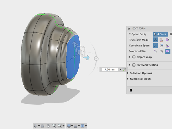
Challenge
ATLAS design challenge
During the preparation week, we are organizing an ATLAS-wide one-day design challenge. One of the ideas of such a challenge is to promote vertical integration within the college; hence, all classes are invited to participate.The theme of this year's design challenge is
Future of design: Freeform & Collaborative
Lizabeth Arum from Ultimaker is joining us. As an Education Community Manager, she has a track record that involves a.o. educational practices for freeform design (for 3D printing). At the start of the day, she will give an introduction into freeform modelling using Autodesk FUSION 360 modeling environment. You will be introduced to the sculpting mode, the patch environment, and how to work collaboratively on one design.After that you will work in small groups on a specific design challenge, namely Design of a smart seat supporting multiple parts of the body in which you can practice with the FUSION 360 modelling environment in a team setting. Details of the design challenge will be given on Monday; however, to make an effective start it is important to collect a number of reference images (jpeg/png/etc.) of possible seats beforehand. For instance:

At the end of the day, all groups present their results to each other and to a jury.
To prepare yourselves for the day, we would ask you to:- Install the FUSION 360 software from the Autodesk website on your laptop beforehand: http://www.autodesk.com/products/fusion-360/free-trial or Fusion 360 for education
- Gather a number of reference images (jpeg/png) of possible seats as mentioned above. You can use these as a starting point for your design in the software environment.
Time table for Monday January 30th (RA2520)
- 10.30h Start with FUSION 360 introduction by Lizabeth Arum
- ~12.00h Start of group work (you are free to plan your activities during this part)
- 16.30h Presentation of group results (including jury feedback)
- 17.30h End of the day
Design of a smart seat supporting multiple parts of the body
After the FUSION 360 introduction, you will work in small groups on a specific design challenge, namely Design of a smart seat supporting multiple parts of the body in which you can practice with the FUSION 360 modelling environment in a team setting.The challenge is to think of a novel idea to make a seat smart(er); i.e. incorporating intelligence through sensors and/or actuators. You are free to decide upon the type of seat and its purpose; however, the seat should support multiple parts of the body.
You should give shape and present your idea using the FUSION 360 modelling environment. Concerning FUSION 360, you are encouraged to make valuable use of the techniques introduced.
Evaluation criteria
- Application of Fusion 360 techniques
- Novelty of concept idea
- Quality of presentation
- Comfort Level
Fusion 360 Basics
Fusion 360 Gallery
Sign up for an Autodesk account and download and install Fusion360. Get Fusion 360 for education
Getting Your Feet Wet
Fusion 360 is a cloud-based CAD/CAM tool for collaborative product development.
1 Application Bar
| Data Panel | |
| File | |
| Save | |
| Undo/Redo |
3 Tool Bar
4 View Cube
This allows you to orbit around the drawing.5 Browser
This allows you to show and hide as well as select objects in your sketch.6 Canvas and marking menu
By CTRL-clicking on the canvas the marking menus appear.7 Timeline
Lists operations performed on your design. Right-click operations in the timeline to make changes8 Navigation
The navigation bar contains commands used to zoom, pan, and orbit your design. The display settings control the appearance of the interface and how designs are displayed in canvas.CTRL-click in an empty area of the canvas to bring up the Marking Menu:
- Open Fusion 360.
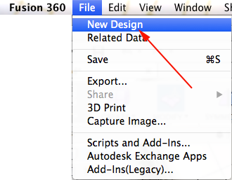
- Fusion 360 will open a new design. However if you are in a design and want to create another one, select File→New Design:
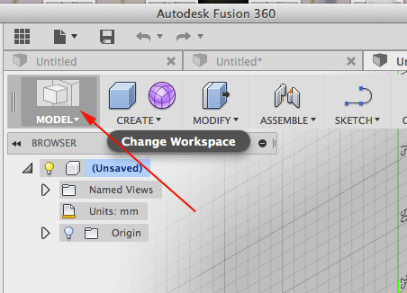
- Select Model mode:
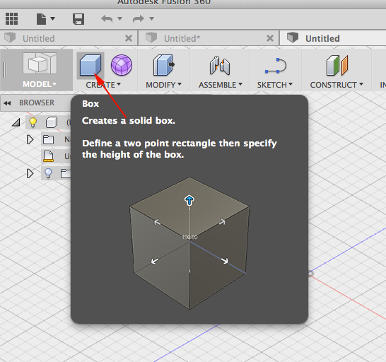
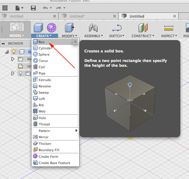
- Click on Box:
- Select Box from the pulldown menu:
- Select the ground plane by clicking on the blue red plane:

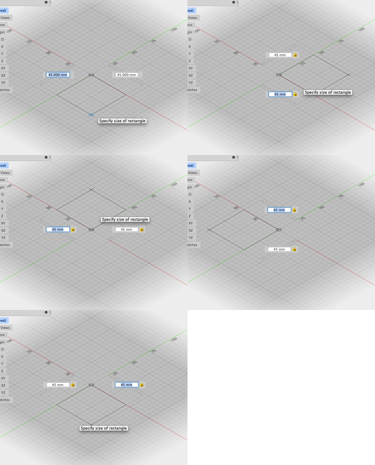
- Click on the center to start drawing.
- Enter a dimension in the field, press Tab and enter the other. Press tab once more and move the cursor into the different quadrants. click to accept parameters:
- Adjust height in the text entry field or in the box window:
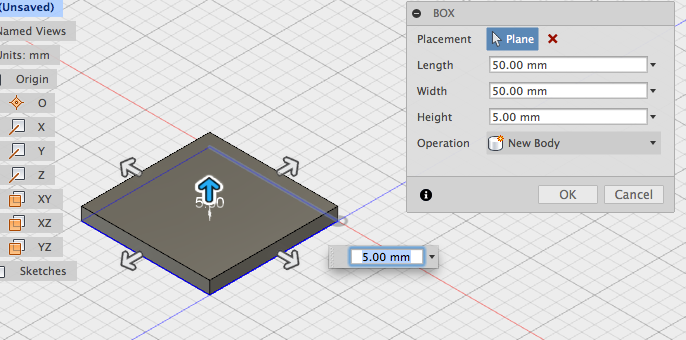
- Press ENTER or click OK to create the box
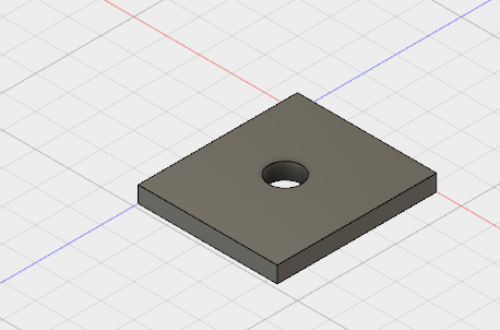
Make a hole
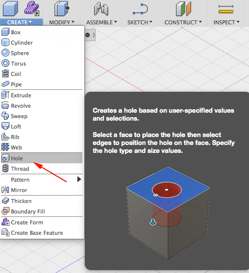
- Click Model → Create → Hole:
- Select the top face of the box:
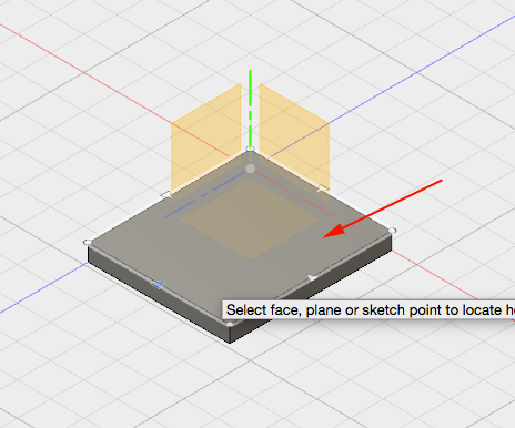
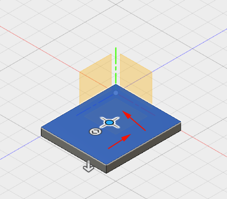
- Drag the center of the hole to the
center of the box:
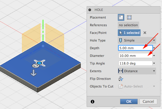
- Set Diameter and height:
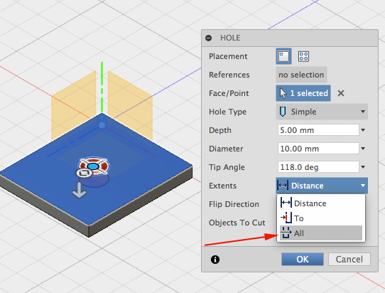
- Change Extents to All:
- Click OK:
Display the Data Panel
- Click in the upper left corner to display the Data Panel:

- The active project name is displayed at the top. Thumbnails of all the designs in the project are listed. All data is stored in A360 in the cloud:
- Click again to hide the Data Panel.>
- Click next to Origin to display
the origin planes:

- Click the light bulb again to turn the origin planes off.
- Click the arrow next to Bodies in the browser to expand the folder. There is one body in this design.

- Find the timeline:

- Left+Click on the fillet to select it. Right +Click to bring up the menu. Select Edit Feature:
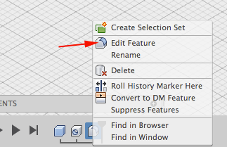
- Change the value of the radius:
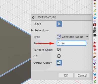
- Click OK:
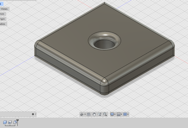
- Select File→3D print or click on the Make Icon.
- Select and export the file.
- Click OK
Keyboard Shortcuts
| Command | Windows | Mac |
|---|---|---|
| Undo | Ctrl + Z | Command + Z |
| Redo | Ctrl + Y | Command + Y |
| Copy | Ctrl + C | Command + C |
| Paste | Ctrl + V | Command + V |
| Cut | Ctrl + X | Command + X |
| Sculpt Workspace Selection | Windows | Mac |
|---|---|---|
| Grow selection | Shift + Up arrow | Shift + Up arrow |
| Shrink selection | Shift + Down arrow | Shift + Down arrow |
| Loop selection | Alt + P | Control + P |
| Loop grow selection | Alt + O | Control + O |
| Ring selection | Alt + L | Control + L |
| Ring grow selection | Alt + K | Control + K |
| Ring shrink selection | Alt + J | Control + J |
| Previous U | Alt + Left arrow | Control + Command + Left arrow |
| Next U | Alt + Right arrow | Control + Command + Right arrow |
| Previous V | Alt + Down arrow | Control + Command + Down arrow |
| Next V | Alt + Up arrow | Control + Command + Up arrow |
| Range selection | Alt + M | Command + M |
| Invert selection | Alt + N | Command + N |
| Toggle box mode | Ctrl + 1 | Ctrl + 1 |
| Toggle control frame mode | Ctrl + 2 | Ctrl + 2 |
| Toggle smooth mode | Ctrl + 3 | Ctrl + 3 |
| Select edge ring | Double-click an edge | Double-click an edge |
| Select face ring | Select two faces then double-click a third face | Select two faces then double-click a third face |
| Edit Form Command | Windows | Mac |
|---|---|---|
| Add geometry | Alt + Drag | Option + Drag |
| Add geometry and keep creases | Alt + Ctrl + Drag | Option + Command + Drag |
Sculpting in Fusion 360: The Sculpt Workspace
Sculpting in Fusion 360 allows for the intuitive freeform creation of organic solid bodies and surfaces by leveraging the T-Splines technology. You can explore forms by pressing and pulling on subdivided surfaces. Sculpted forms are easily converted to solid bodies, and can be used in conjunction with Fusion 360's solid modeling commands.
One of the main advantages of T-Splines is the ability to add detail only where necessary - a single T-Spline surface can be smooth, while still having areas of high detail and remaining easy to manipulate. T-Splines allows designers to: Add detail only where necessary
Create non-rectangular topology
Easily edit complex freeform models
Maintain NURBS compatibility
When in the Sculpt Workspace you have access to the Gizmo, which lets you manipulate vertices, edges and faces. The Gizmo has this name because twenty years ago 3D Studio Max called this tool the Gizmo.
The Gizmo allows you to translate a face, vertex, edge along an axis or a plane, and lets you scale and rotate your selection. If you double click on a single edge, Fusion will select the whole chain, or tangential lines.
When working in the Sculpt environment, the only option undo a step is to go back through through the last twenty or so steps. The number of undos is based on your RAM and how much cache space is left.
In addition to extruding and revolving, you can also generate a T-Spline body by sweeping a profile. Sweeping is commonly done with circles, however any closed shape can be used in conjunction with a line in a sweep to produce a solid.
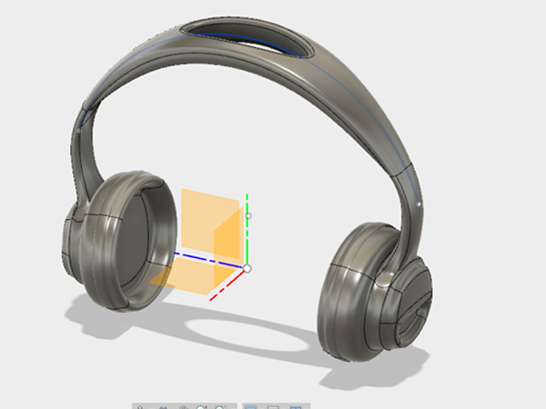
This tutorial is based on "Overview of how to design your own headphones"
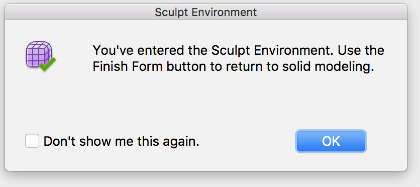
- Open the Sculpt Workspace. A dialog box will appear telling you to click Finish Form to return to the model workspace when you are finished sculpting. Select OK:
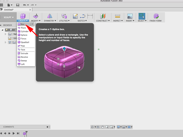
- Select the drop-down arrow under Create to expand the list of creation commands. Select Box under the Create menu to create a T-spline box:
- When you create a new primitive you first need to indicate which plane you want to build on and then enter the dimensions of the primitive. Select the YZ Plane :
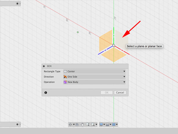
- Select the origin to specify the center point of the box 2D profile. Drag the mouse and click on the plane again to specify the initial size of the rectangle. Create a box with symmmetry across the length:
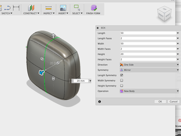
- Rotate the workspace to face the top of the box:
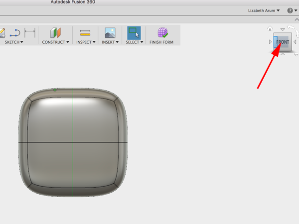
- Select edge and pull corner of gizmo to round box:
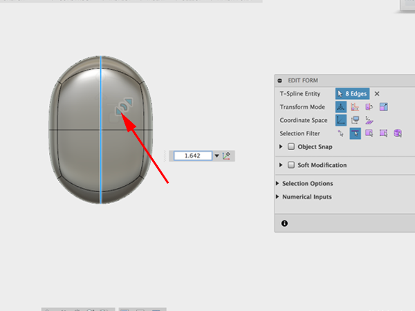
- Select other edge and drag gizmo to round:
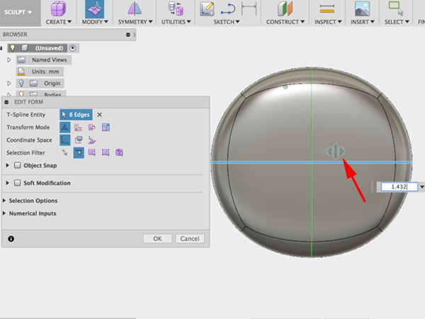
- Select the four faces and while holding down on the alt key, drag to the left. You should create new faces:
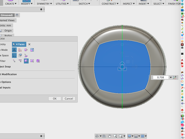
- Select the faces, hold alt while dragging to make smaller new faces and hold down alt while you extrude:
- Select the two bottom faces and hold alt while dragging to create new faces. Then hold alt while pushing in:
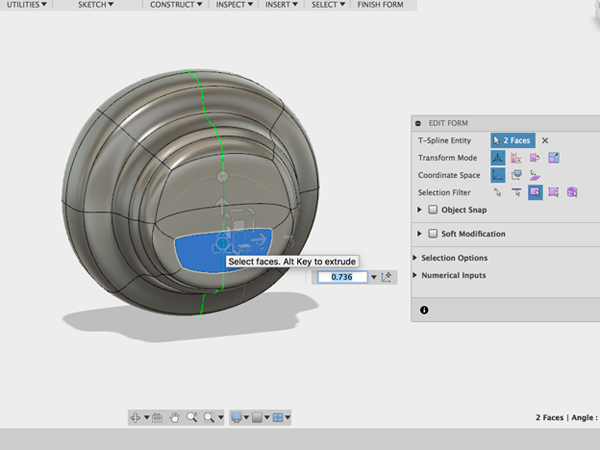
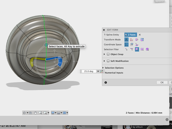
- Select the two faces and rotate:
- Rotate around to the other side of the model and select the four faces. Then hold alt and drag to the left:
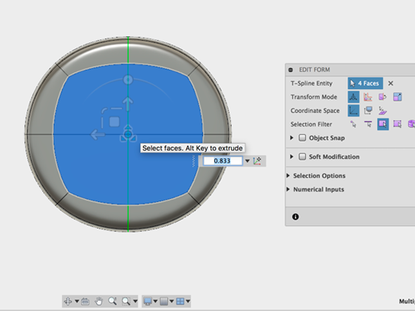
- Holding alt, move the new faces inward:
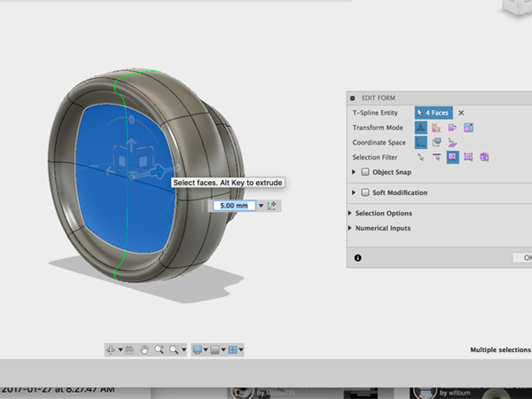
- Continue to edit until you get what you want:
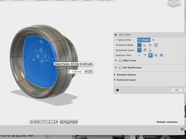
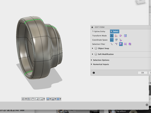
- Select Insert edgeClick on the center edge:
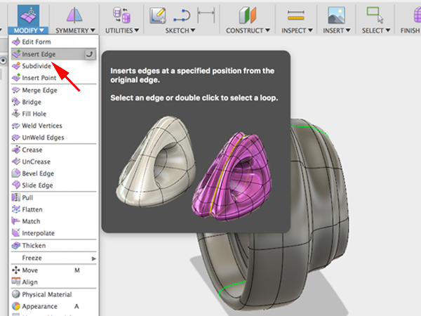
- Move the green edge forward:
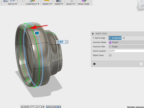
- Select the faces between the center edge and the new edge you made:
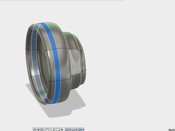
- Holding alt scale the faces up a little:
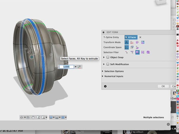
- Now using the gizmo, thicken the selection:
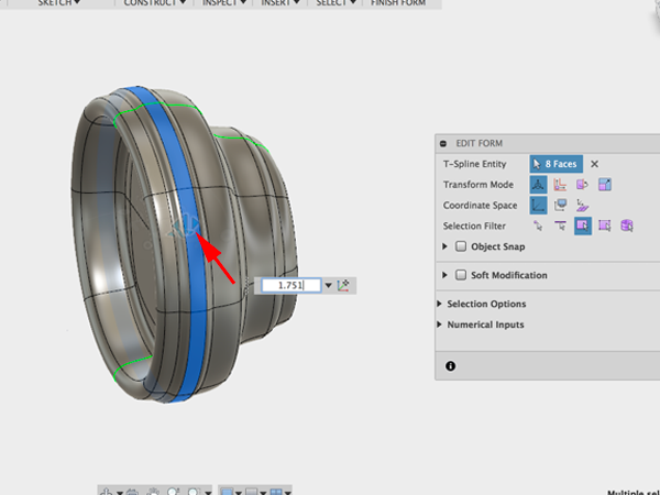
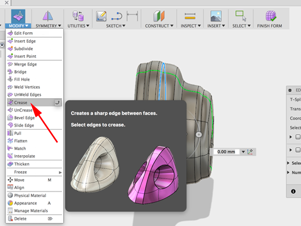
- Select the edge behind the center edge. You are going to make a hard edge:
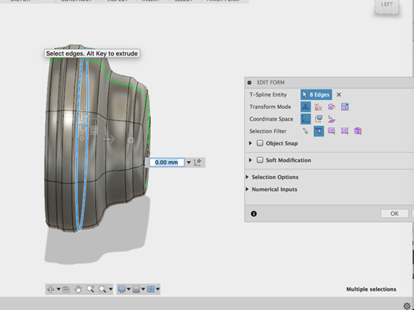
- To create a hard edge, Select Crease:
- Sculpt the back part until you get the shape you are after:
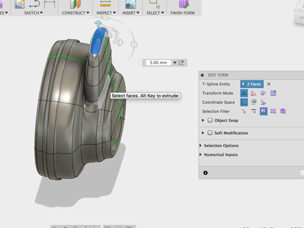
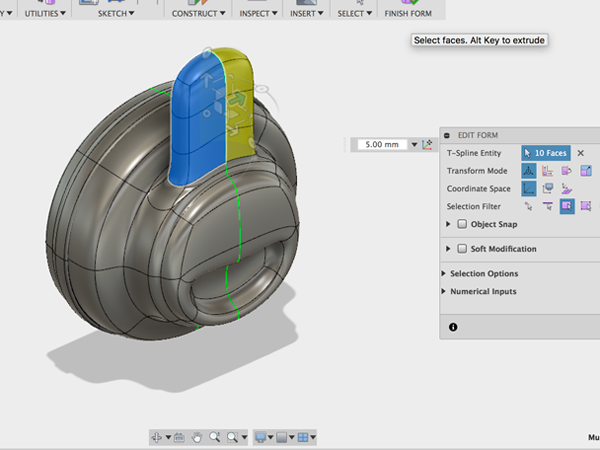
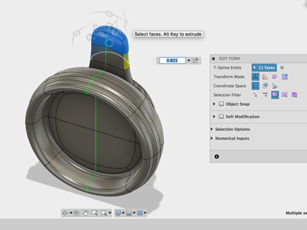
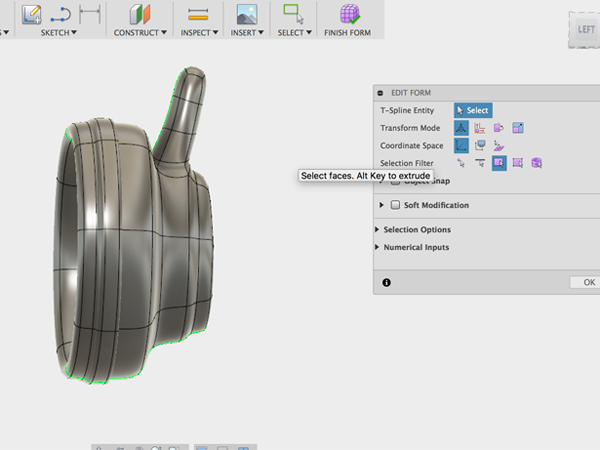
- Using the gizmo, move the entire form over and rotate slightly:
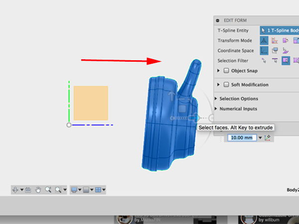
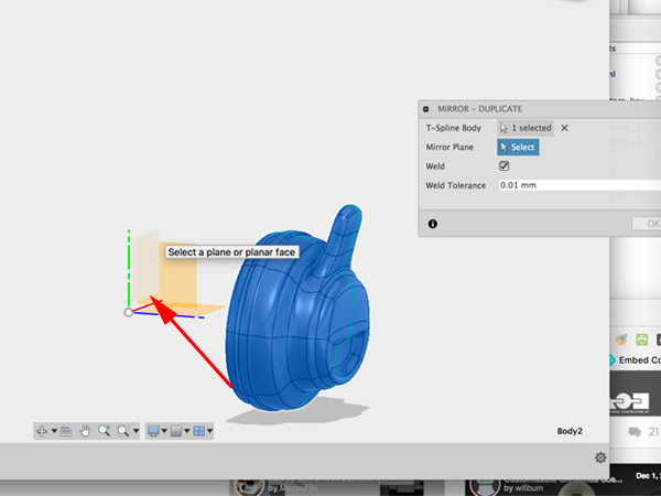
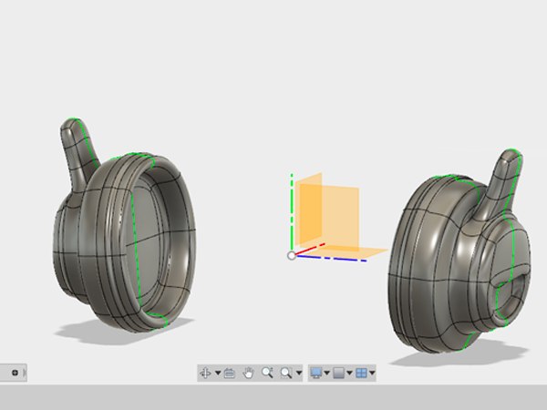
- To make the other side of the headphones, you can use Mirror - Duplicate:
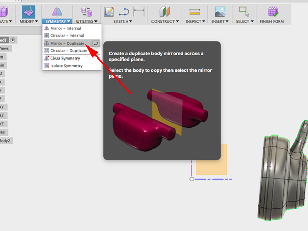
- For the Axis to mirror over, select the XY plane:
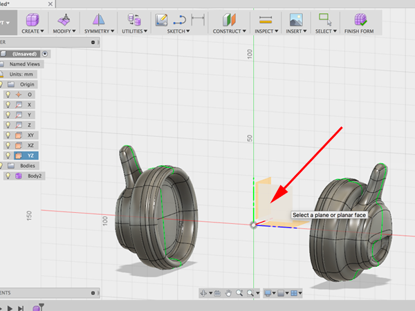
- Create a Sketch and select the YZ plane:
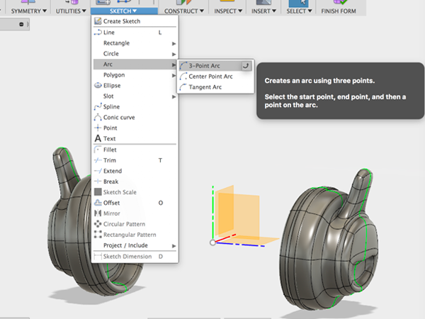
- Select 3-Point Arc:
- Create the starting and ending points:
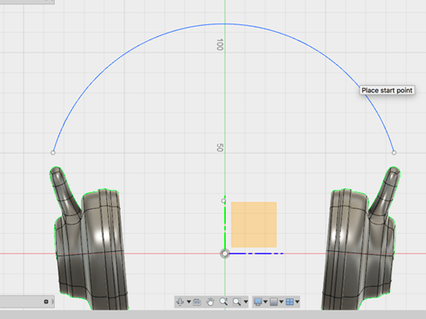
- Select Bridge:
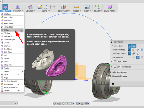
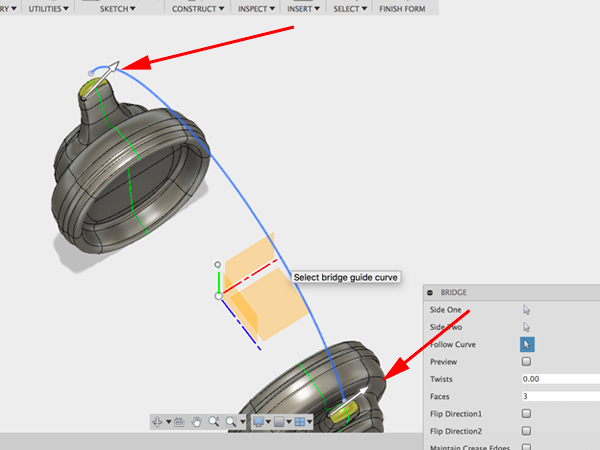
- First click on the top faces of one side, then select the top faces of the other side. Select the arc as the curve to follow:
- Adjust the properties so that the preview is positioned in the right direction:
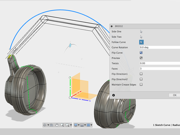
- Press OK:
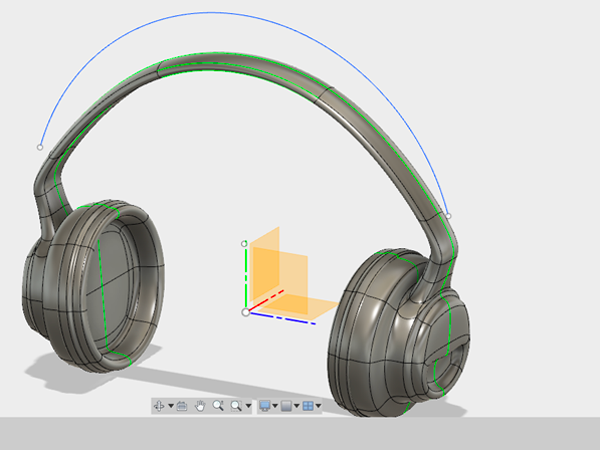
- Edit the top section using the gizmo. When you have the shape you want, CTRL+click on the surface in the browser and select Convert. This will convert your form from a surface to a solid body.
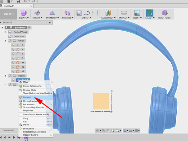
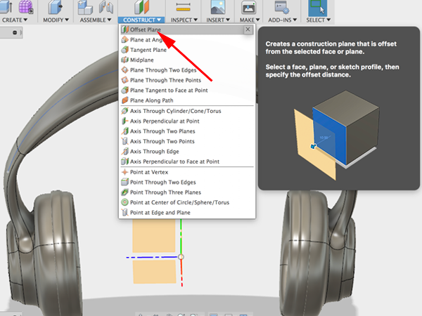
- Notice that you are now in Model mode. Seelct Offset plane:
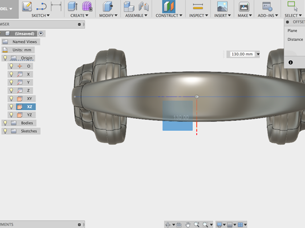
- Click on the XY plane and raise the offset plane above your form:
- Select Create sketch:
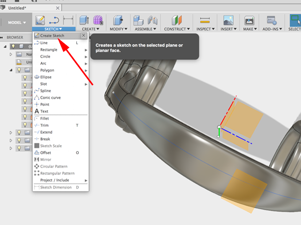
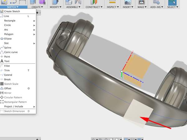
- Select the offset plane:
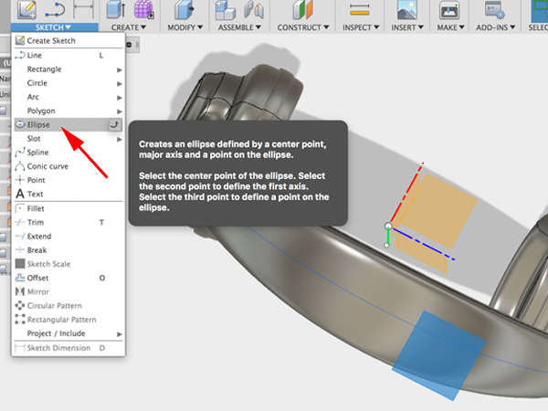
- Select Ellipse:
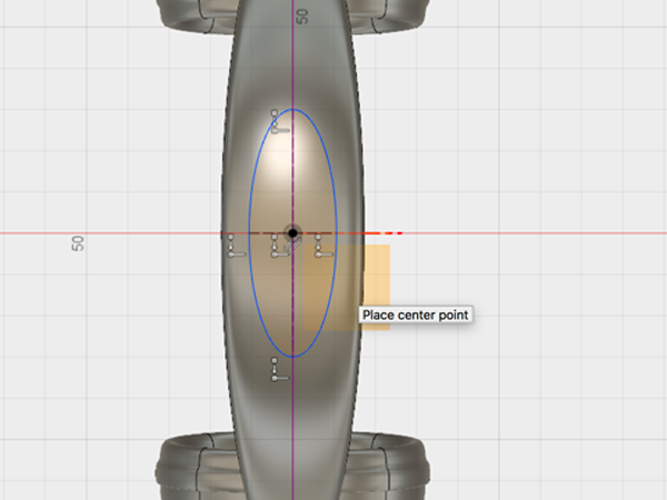
- Draw a centered ellipse:
- Use Extrude to cut a hole:
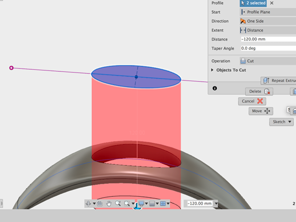
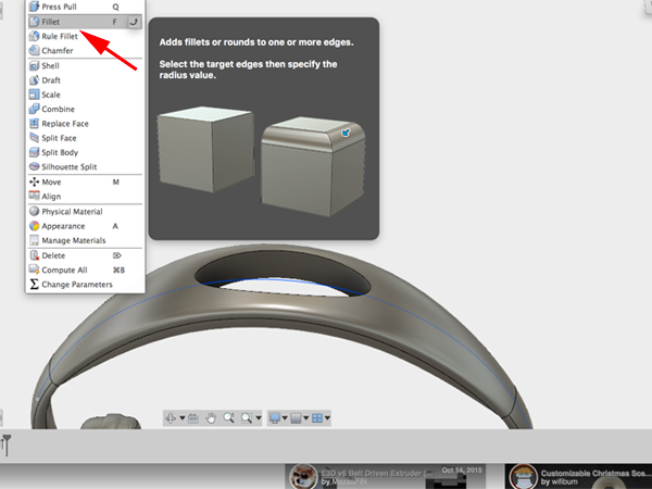
- Select Fillet and add fillets to the top and bottom of your hole:
- Save your work
Reference Images
When sculpting a shape with T-Splines it is helpful to have a reference image to guide you. Reference images can be sketches or photographs that are set in the background of the workspace to model from. In Fusion 360 you can attach an image to a work plane and then calibrate the image so that you are modeling in the correct scale.- Select Insert:Attached Canvas
- Select a plane to indicate which plane the image should be attached to.
- In the dialog window, click the Select Image button and navigate to your image
- Lower the opacity to around 85. Check the box for Display Through to ensure that the canvas can be seen through your T-Spline form. Click OK: Note: You don't need to be concerned about the size and scale of the image at this point. You will adjust the scale using the Calibrate tool. Calibrating the image ensures that you are modeling in the correct scale in the workspace
- In the Browser, click the drop-down arrow next to the Canvases folder
- CTRL-click on the image and select Calibrate.
- Click on the ViewCube to change the view.
- Click a point on one side of what you know the dimension of. Then click on the other side. Enter the measurement. The attached referenmce image will scale up accordingly
This tutorial is based on Surface Modeling with Fusion 360
- Download this image:

- Select Insert:Attached Canvas and navigate to the image you downloaded:
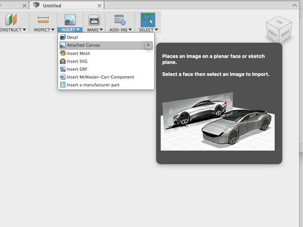
- Select the XY plane to attach the image to.
- Lower the opacity to around 85. Check the box for Display Through to ensure that the canvas can be seen through your T-Spline form.
- Click OK.
- In the Browser, click the drop-down arrow next to the Canvases folder
- CTRL-click on the image and select Calibrate.
- Click on the ViewCube to change the view.
- Click a point on the top. Then click a point on the bottom. Enter the measurement of 100. The attached referenmce image will scale up accordingly
- CTRL-click on the image in the Canvases menu and select Edit Canvas.
- Move the canvas to align with the axis:

- Open the Sculpt environment:
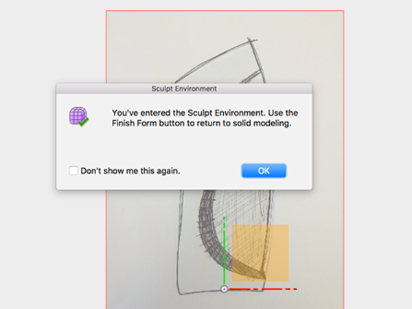
- In the Sculpt Environment add a cylinder to the XZ plane:
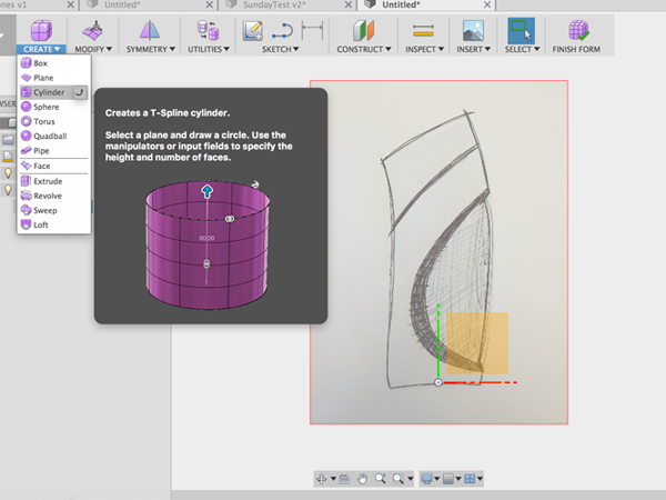
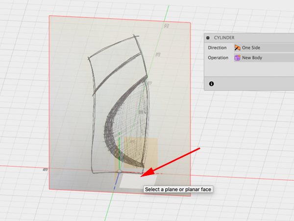
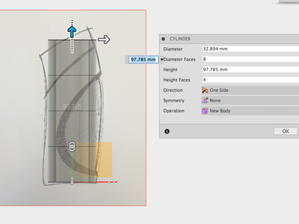
- Adjust properties of cylinder:
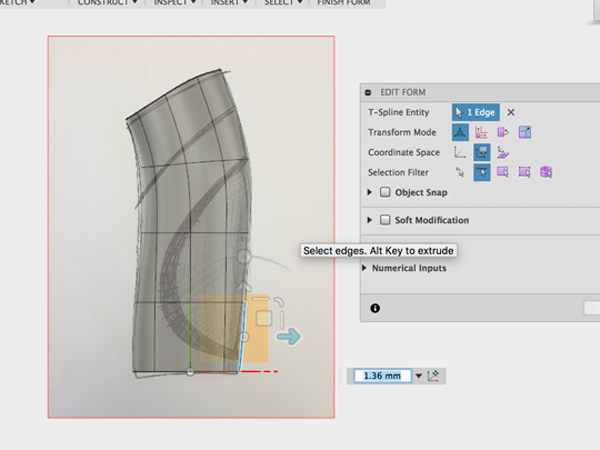
- Edit the form to match the sketch:
- Finish the form and enter the Patch environment:
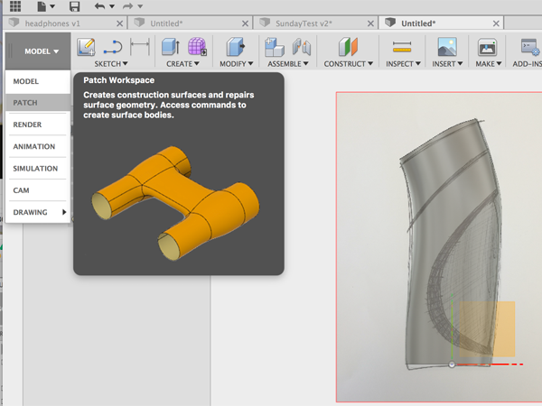
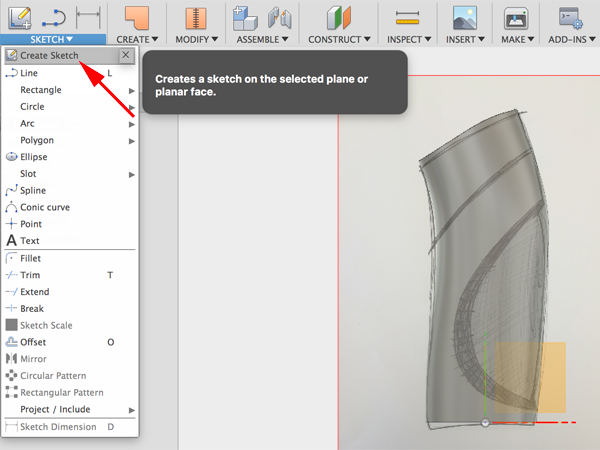
- Select Create Sketch:
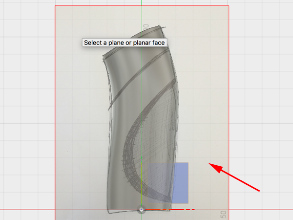
- Select the canvas to sketch on:
- Select spline:
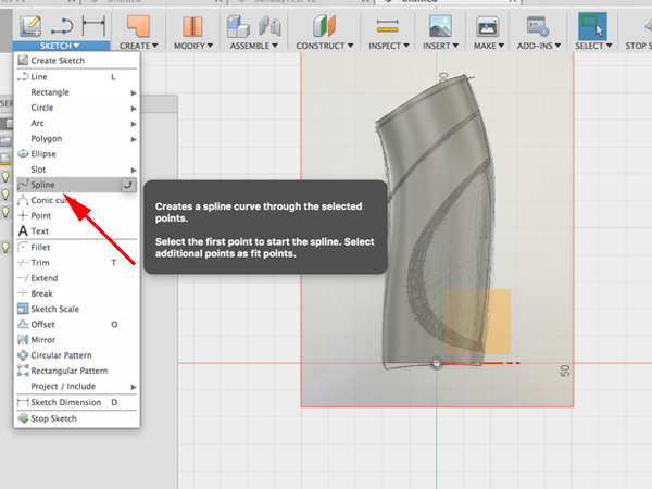
- Draw splines to matc the sketch:
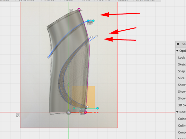
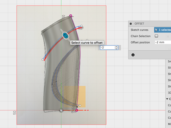
- Select offset to the top spline:
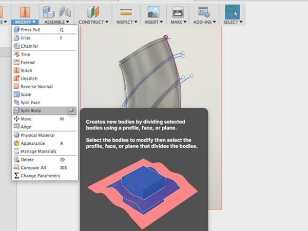
- Select Split Body:
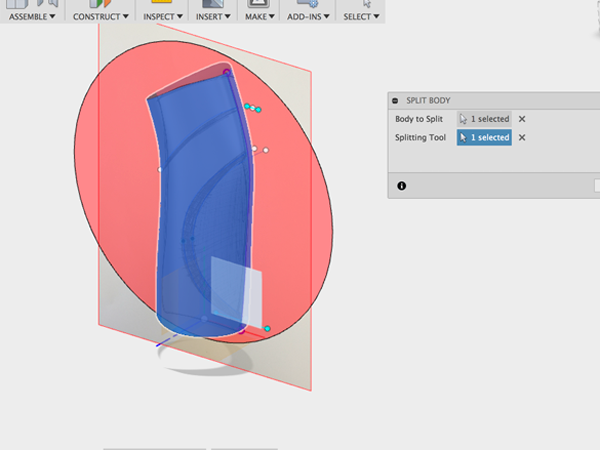
- Click on body to split and plane to cut with:
- Turn off the back:
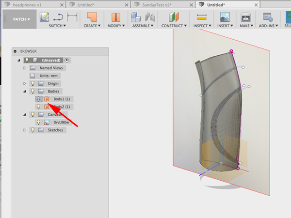
- Select Split Body again:
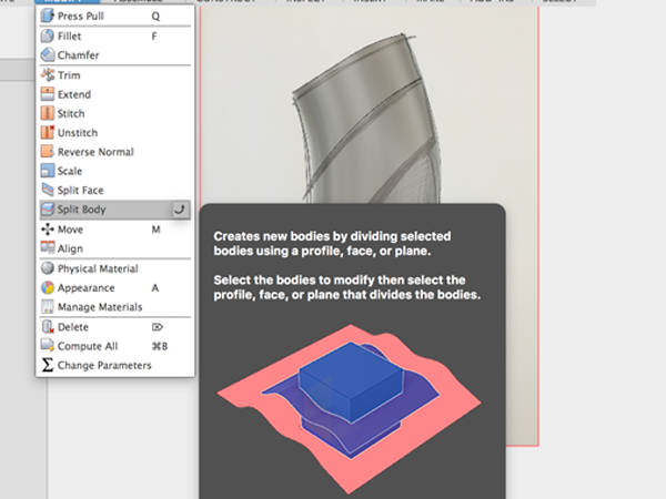
- Click on the body to split and the top spline to cut with:
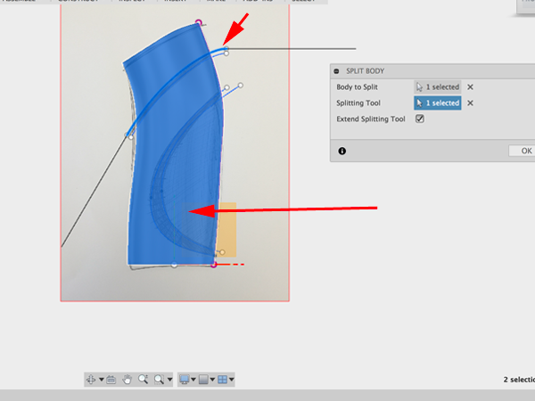
- Make another split of the body and the top spline of the second group to cut with:
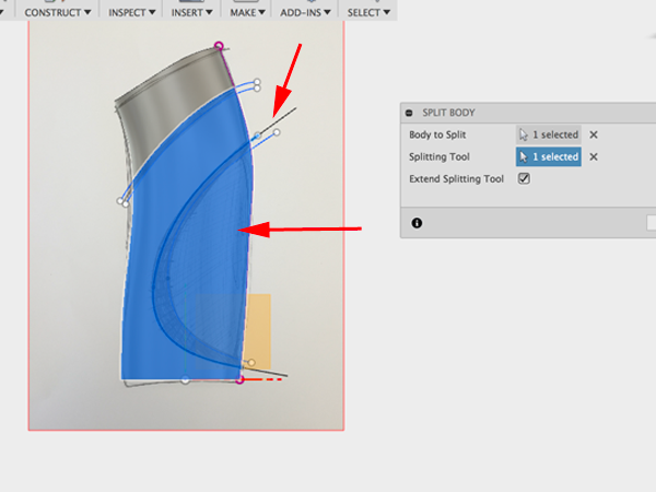
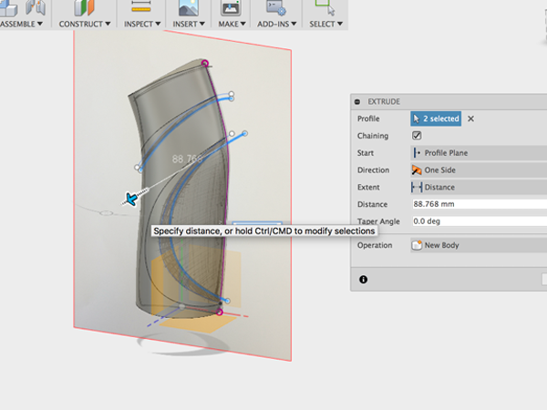
- Extrude the offset line and the second spline:
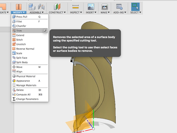
- Select Trim:
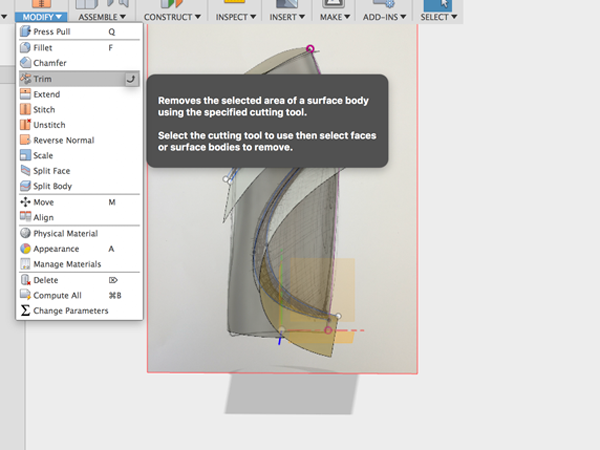
- Select the extruded surface and the small piece below the first split:
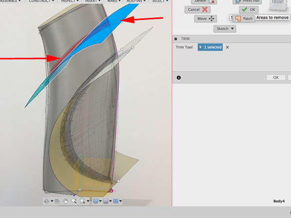
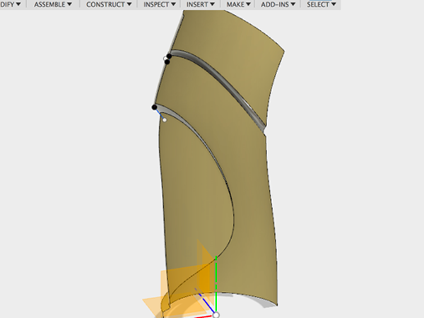
- Select Trim again:
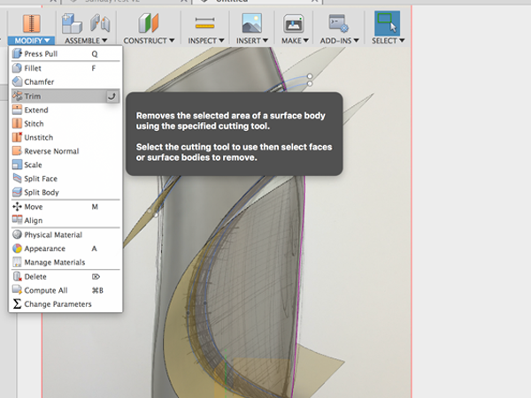
- Select the surface and the small piece above it:
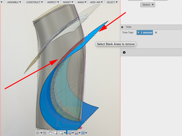
- Turn off the canvas:
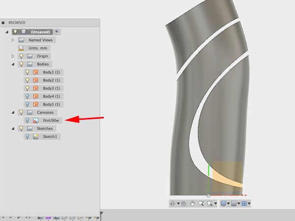
- Select Offset from the Create menu and select third piece:
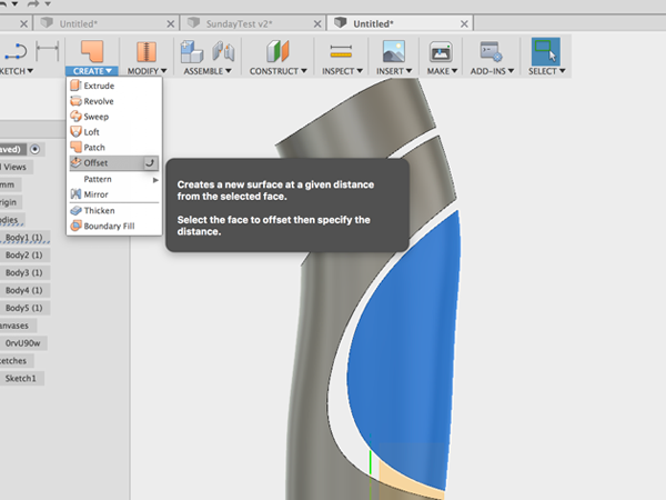
- Move the piece:
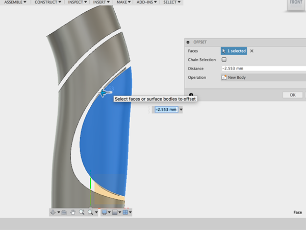
- Turn off the original piece:
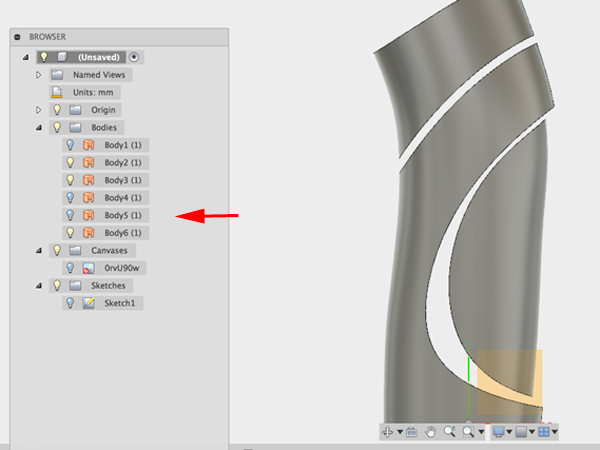
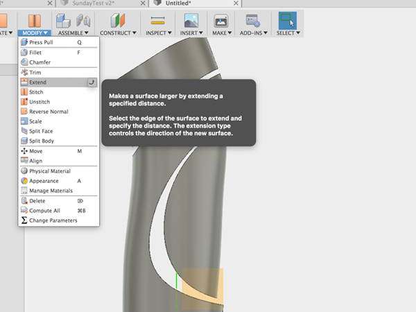
- Select Extend and select the edge of the offset piece:
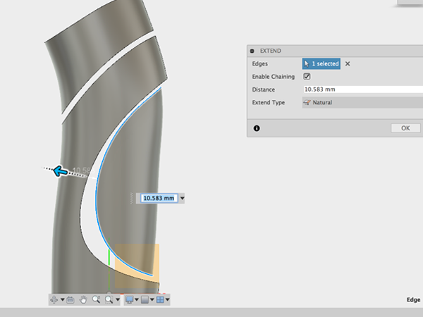
- Move the edge so that it completely extends through the body:
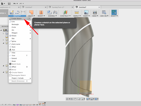
- Create a sketch:
- Select the plane:
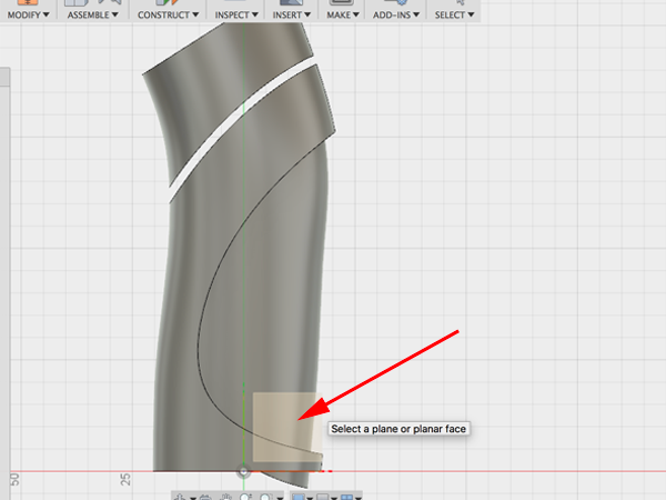
- Select Project:Intersect:
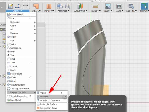
- Select the three points:
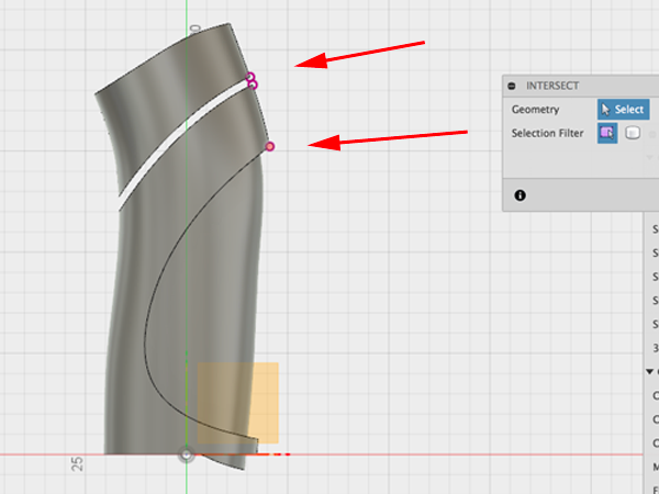
- Make a small line:
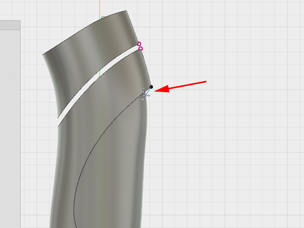
- Select 3-Point Arc:
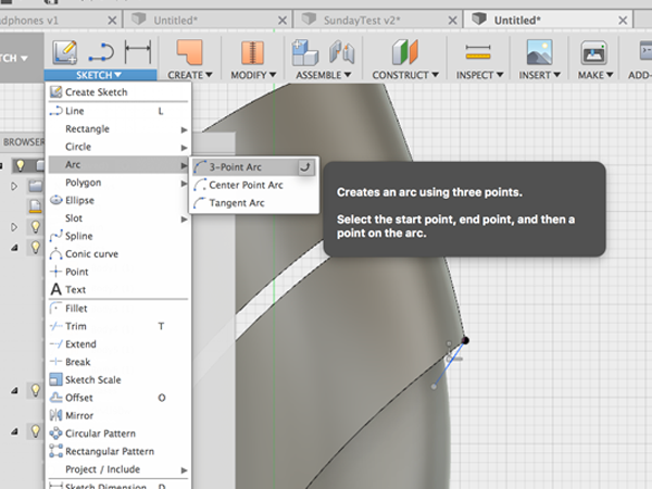
- Create the arc between the 2 points:
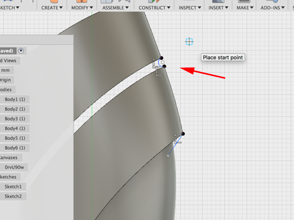
- Click Sweep and select the arc as the profile:
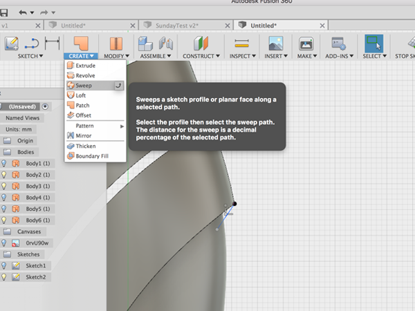
- Click on the top line for the path:
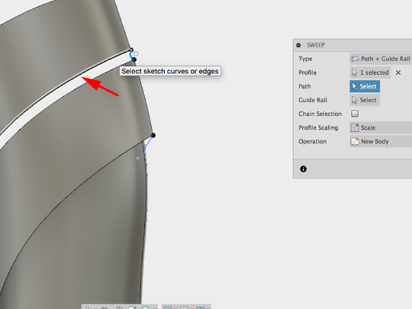
- Click on the bottom line for the rail:
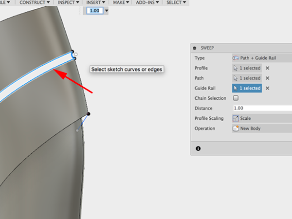
- Select Sweep:
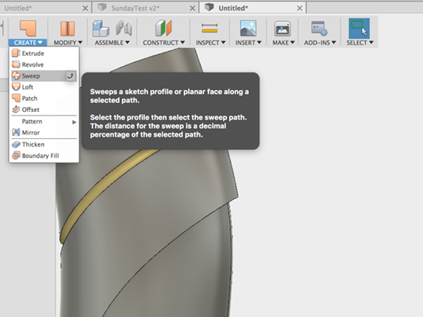
- Click on the small line for the profile:
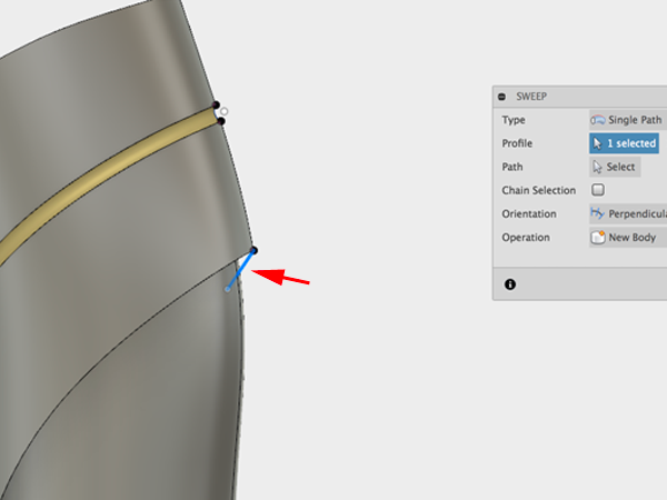
- Click on the line for the guide:
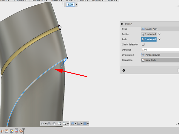
- Turn and trim:
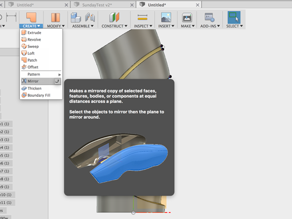
- Select Mirror:
- Select all the parts:
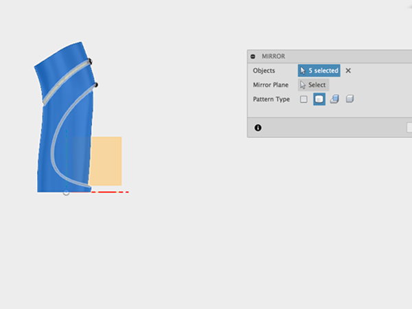
- Select the plane to mirror over:
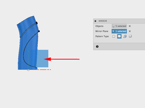
- Select Patch:
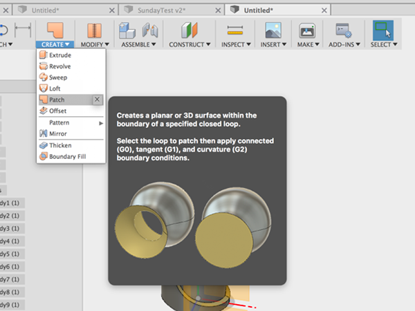
- Select the top edges:
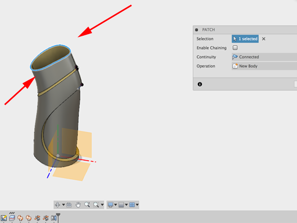
- Patch the bottom:
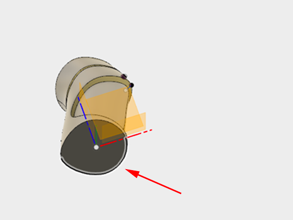
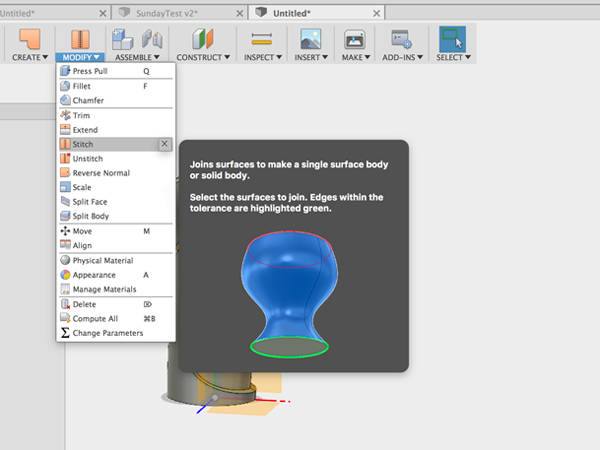
- Select Stitch:
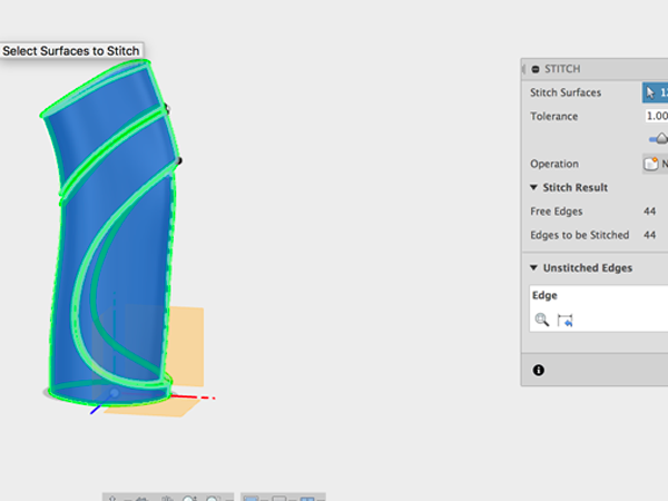
- Select all to stitch:
Parametric Modeling and Sculpting: The Patch Environment
Creating a bend
The following information was derived from x's y tutorial.- Open Fusion 360:

- Open Patch mode:

- Create a spline:

- Select your plane:

- Draw your spline:

- Adjust your spline:

- Stop the sketch:

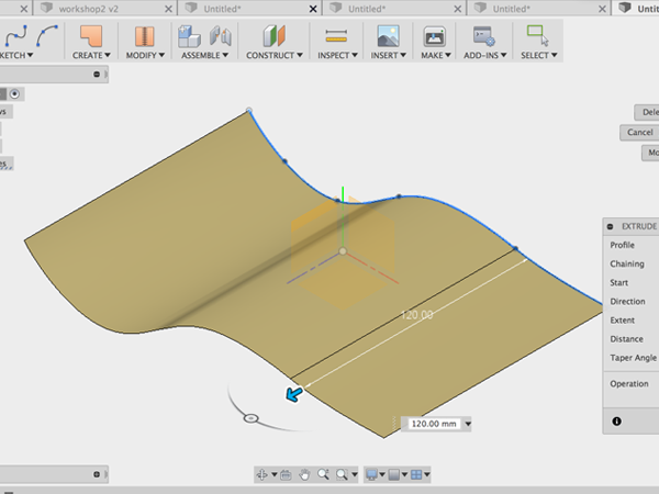
- Select Extrude:

- Extrude the spline:
- Create a new sketch and select the XY plane:

- Rotate to see that the bottom sketch is completely underneath the curved surface:

- Ctrl+click on the closed profile and select model extrude:

- Be sure to turn on intersect:


- In the Create menu, select Thicken and thicken the surface:

- In Model mode, select the top face:

- From Modify menu, select Fillet Rule:

- Add the fillet:

- Repeat for the bottom:

- Add the fillet:

- Return to Patch mode:

- Adjust the original spline and see how this affects your form:

- Adjust the other sketch:

- You can dimension your sketch:

- Then you can adjust the dimensions to affect the form:


Designing an Arduino Uno Enclosure
The following information was derived from x's Designing an Arduino Uno Enclosure tutorial.
- Create a New Project in Fusion 360.
- Download, open and save in your project:Kevin Schneider's Arduino
Here are dimensions for the Arduino:
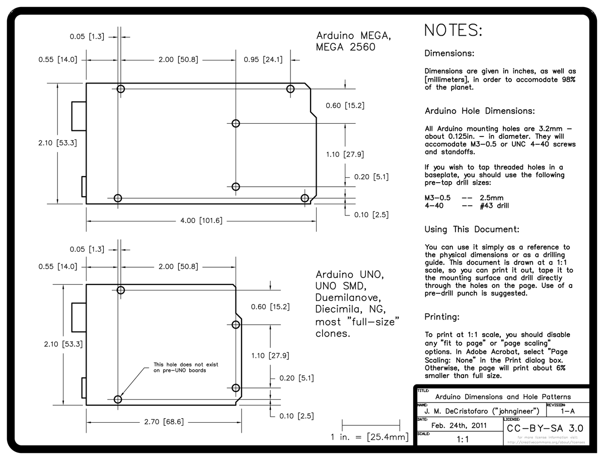
Here is an example of an Arduino enclosure:
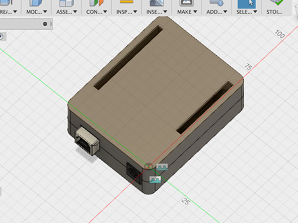
- Create a sketch and make a rectangle that is the dimension of an Arduino:

- Add an offset so that the Arduino can fit inside the enclosure:

- Offset by 1mm:

- Add circles with adiameter of 2.8mm. This is smaller than the Arduino holes, but this diameter will fit inside the 3.2 mm mounting holes:

- Add four circles

- Open up Sketch Dimension

- Use Dimensioning to arrange the mounting holse where they are supposed to be:

- Stop the Skectch:

- Select Extrude and extrude the base by 22mm:


- Select fillet:

- Apply a fillet of 3mm to the corners:

- Select Shell:

- Create a shell of 1.6mm. Make sure you select outside since you have created your shape that was offset by 1mm from the Arduino base dimensions:

- Create a Midplane construction plane:

- To find the midplane, click on the top face and then the bottom plane:


- You are going to use the midplane construction as a splitting tool. Select Modify:Split Body:

- Select the box as the body to be split and the plane as the tool:

- In the browser, hide the top of the box:

- Select extrude and extrude the circles by 15mm (11mm to reach the top and 4mm to extend to the other side):

- Select Create Sketch:

- Create a new sketch on the face of the bottom of the box:

- Make four circles with the same center point as the pins. Make the diameter 4mm:

- Select Extrude:

- extrude by 4mm and make sure New Body is selected:


- Hide the bottom. Show the top:

- Create a sketch on the interior face of the top part of the box:

- From the Sketch menu, select Project:

- Turn off the top body, turn on the bottom body and select the top faces of the pins to project:

- Turn off the bottom:

- Use the projected circles as your guide to make new circles with a diameter of 3.2mm:

- Create another set of circles with a diameter of 5.2mm:

- Turn on the top body:

- Select Extrude and extrude the cylinders by 10mm:

- Tuurn off the top and turn on the bottom. Select Chamfer:

- Select the tops of the pins and chamfer by .4mm:

- Select Combine:

- Select all the elements you want to comprise the bottom of the box:

- Select Combine again. Select all the elements you want to comprise the top of the box:

- CTRL+click on the bottom body in the browser and select Make Component. Name the component bottom:

- CTRL+click on the top body in the browser and select Make Component. Name the component top:

- Navigate to the data panel. CTRL+click on the Arduino and bring it into the current project. You can also rotate it by -90:

- In the Browser, CTRL+click on the bottom and select Ground. This will pin the component in place:

- Select Assembly:Joint:

- Select the bottom of the mounting hole on the Arduino:

- Select the top of the corresponding 4mm cylinder on the bottom. Make the connection Rigid.The Arduino should move into place:

- Select Assembly:Joint:

- Select these two points on the top and bottom to align them. Make the connection Rigid:

- Create an offset plane:

- Select the side face:

- Create a sketch and select the offset plane

- Select Project

- Carefully select the edges of the power and USB jack:

- Turn off the Arduino. Offset the edges by .5mm:

- Select Extrude:

- Extrude the offset and the original edges just to the other side of the bottom wall:


- Create a sketch on the top of top. Select Project. Hide top and click on the diagonal corners of the Arduino pins:

- Turn the top back on:

- Use the Rectangle to create rectangles based on your projected pins:

- Select Offset:

- Offset the rectangle by .5mm:

- Save.
Collaboration
On left side, open the Data Panel. Collaboration starts with fact that it is cloud based software. You don't store your files locally. Files are saved on Autodesk servers at Amazon Web Services, so you'll always be able to see your files.
Fusion allows you to add people to a project. Once invited, your invitee will get an email. They can then see your project in their data panel. You might be asking: Does that mean anyone can edit, download and delete your files? The answer would be yes.
Fusion is working on preventing that, but at the moment you either have full access to a project or you don't have access, so be careful.
Two people can open the same file at the same time, but they will be working on different instances of the file. Once on person saves the file, the other person will see that they are not working on the most recent version. If they update the file, they will lose everything they have just done and see what their collaborator has done. If you save first, then your version becomes the most recent.
A new version is created on the server in Seattle Washington. The collaborator will get a notification that they are not working on the most recent version, that it is out of date. If you update you will create a new version with all the changes made in the last version, but you will lose what you were working on.
Companies pay PDM systems, basically a Data management systems 10-15K per person a month. Fusion offers this functionality for free. The data will always exist on the server—this is beneficaial. Large companies might pay millions for this functionality. All this functionality is taken care of from the cloud.
Ability to add comments. Click on an aspect of the model, take a photo, write a comment.
Information: who is using the file, who is doing what, versions A lot of viewing and collaboration capabilities that are not in Fusion 360. In the data panel, click on the name of the project ( use firefox or chrome) and you will be taken to myhub.autodesk360.com All the projects are now viewable in a browser.
- All the files
- Activity-whats going on
- overview-information, thumbnail. the thumbnail allows you to share what your project looks like with someone who does not have the same modeling application as you. So if someone does not have fusion, they can still access the file as long as they have been invited
You are able to view versions and notes. At any point you can select one of the previous versions and promote it to the most recent version. Handy if new changes are rejected
Viewer
Viewer is a powerful option. Works with any browser. works with almost almost all Autodesk CAD formats and all standard formats, SolidEdge, ProE and some Solidworks files.- Explode
- Mark up
- Notes, add comments
Properties
Share your files Calendars—set up due dates You can put any files in the project and they will be usable in the viewer. So if you upload a word doc and your collaborator does not have Word, they will still be able to read it in the viewer.Collaboration in Fusion 360
