Introduction
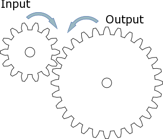
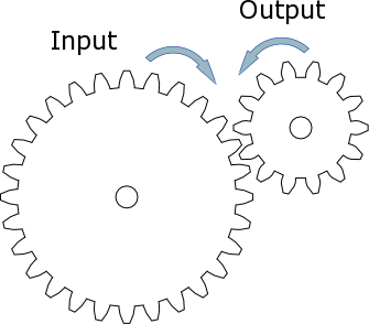
Gears are used to slow down a motor or to give the mechanism more strength. The torque of the gear is its rotating strength. If the input gear (driver) of a gear train is smaller than the idlers or driven gear, the larger gear will move slower, but the torque will be stronger.As speed increases, the strength of the torque decreases (large input).
As speed decreases, strength increases (small input).
Gears are also used when a mechanism that is controlled by a motor is separated from the motor by geometry. Gears allow you to transfer the rotation of the motor across this geometry. When designing a gear train, you will often work from a mechanism back to the motor.
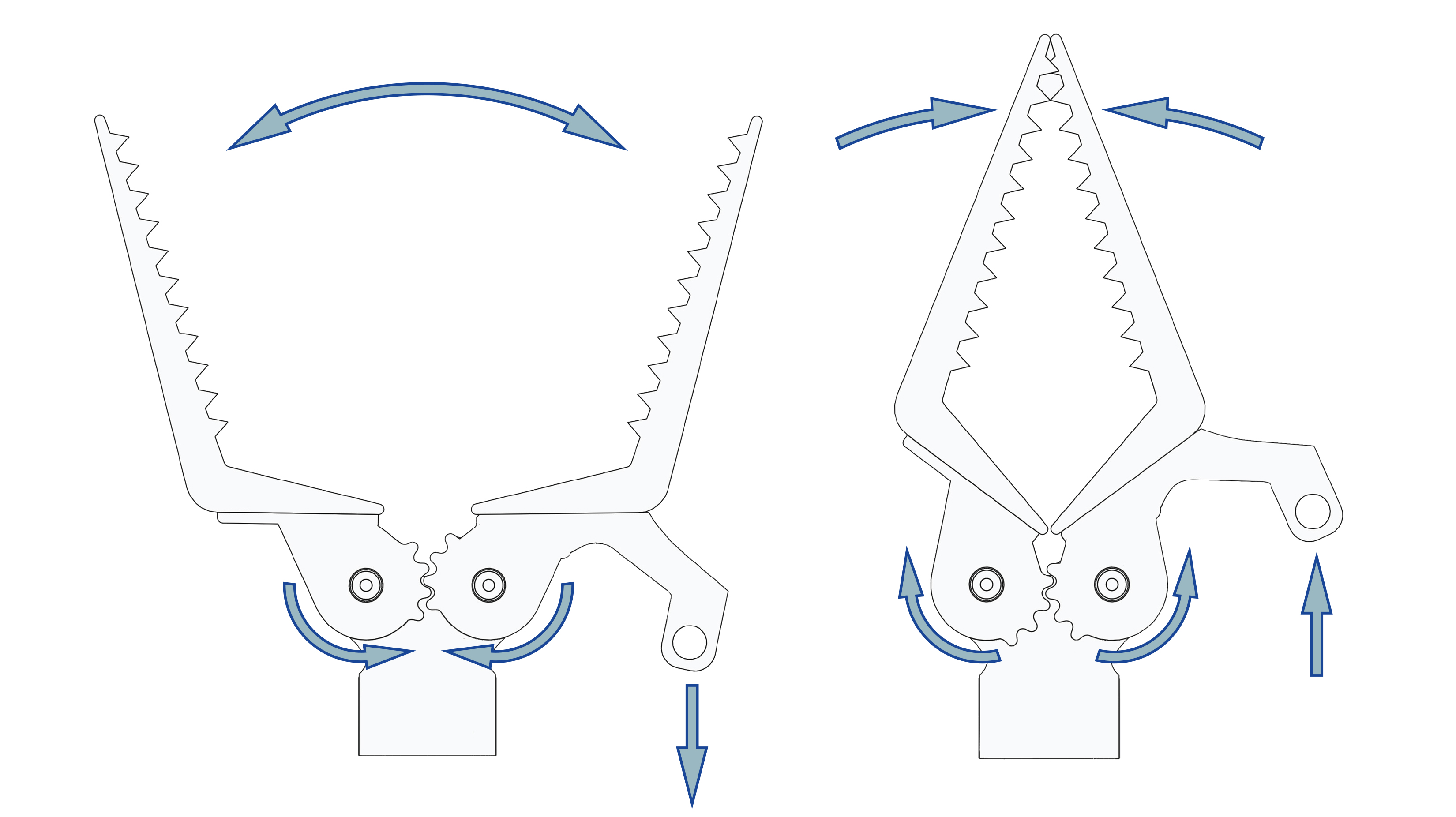
Gears with the same number of teeth moving in the opposite direction from each other can be used to create a claw:
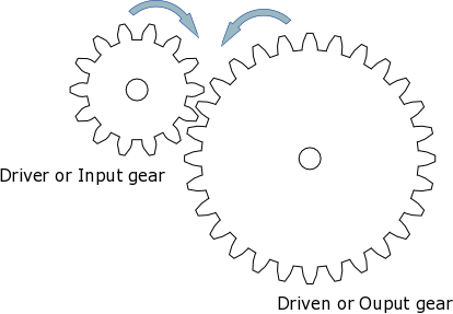
Gears also alter the direction of rotation. In the above example gear wheel A is rotating clockwise, but as it turns, gear wheel B is moved anti-clockwise.
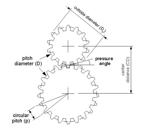
Image from hackaday.com
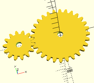
If you know any two things about a gears—outer diameter and number of teeth—you can use some simple equations to find everything else you need to know, including the correct center distance between them.
- Number of Teeth (N)
- How many teeth are there in the gear
- Pitch Diameter (D):
- The circle on which two gears effectively mesh, about halfway through the tooth. The pitch diameters of two gears will be tangent when the centers are spaced correctly.
- Diametral Pitch (P):
- The number of teeth per inch of the circumference of the pitch diameter. Think of it as the density of teeth—the higher the number, the smaller and more closely spaced the teeth on a gear. Common diametral pitches for hobby-size projects are 24, 32, and 48. The diametral pitch of all meshing gears must be the same.
- Circular Pitch (p) = pi / P:
- The length of the arc between the center of one tooth and the center of a tooth next to it. This is just pi (Π = 3.14) divided by the diametral pitch (P). Although rarely used to identify off the shelf gears, you may need this parameter when modeling gears in 2D and 3D software like we're doing here. As with diametral pitch, the circular pitch of all meshing gears must be the same.
- Outside Diameter (Do):
- The biggest circle that touches the edges of the gear teeth. You can measure this using a caliper like Sparkfun.com's # TOL-00067.
Note: Gears with an even number of teeth are easiest to measure, since each tooth has another tooth directly across the gear. On a gear with an odd number of teeth, if you draw a line from the center of one tooth straight through the center across the gear, the line will fall between two teeth. So, just be careful using outside diameter in your calculations if you estimated it from a gear with an odd number of teeth. - Center Distance (C):
- Half the pitch diameter of the first gear plus half the pitch diameter of the second gear will equal the correct center distance. This spacing is critical for creating smooth running gears.
- Pressure Angle:
- The angle between the line of action (how the contact point between gear teeth travels as they rotate) and the line tangent to the pitch circle. Standard pressure angles are, for some reason, 14.5&Acir;° and 20°. A pressure angle of 20° is better for small gears, but it doesn't make much difference. It's not important to understand this parameter, just to know that the pressure angle of all meshing gears must be the same.
- Addendum:
- how much the tooth protudes beyond the pitch radius
- Dedendum:
- how deep goes the tooth before any fillet take place
- Pressure angle:
- The angle between the radial direction and the tangent to the tooth at the pitch circle. 20 is a good value.
Some Rules
The value of the base circle is based on pressure angle.- The smaller the pressure angle, the smaller the base radius
- The addendum must be less than the dedendum
- The dedendum must be more than the difference between the pitch and the base radius.
All of these gear parameters relate to each other with simple equations.
| To Get | You Have | Equation |
|---|---|---|
| Diametrical Pitch(P) Number of teeth per unit length |
Circular Pitch(p)
Number of Teeth(N) & Pitch Diameter(D) Number of Teeth(N) & Outside Diameter (Do) |
P=Π/p P=N/D P=(N+2)/Do(approx) |
| Circular Pitch(p) Length of the arc from one tooth to the next |
Diametrical Pitch (P) | p=Π/P |
| Pitch Diameter(D) | Number of Teeth(N) & Diametrical Pitch(P)
Outside Diameter (Do) &Diametrical Pitch(P) |
D=N/P D=Do-2/P |
| Number of Teeth(N) | Diametrical Pitch(P) & Pitch Diameter(D) | N=P*D |
| Center Distance(CD) | Pitch Diameter(D)
Number of Teeth(N) & Diametrical Pitch(P) |
CD=(D1+D2)/2CD=(N1+N2)/2P |
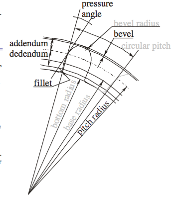
Image from Blender Mechanical Gears 0.0.2©2004 Stefano <S68> Selleri
 This
Stepping up produces a much faster output
speed, but mechanically delivers less power.
This
Stepping up produces a much faster output
speed, but mechanically delivers less power.Calculation Ratios
If the input gear has 10 teeth and the output gear 40 teeth, then the ratio is termed 4 to 1 and is written down as 4:1
Ratio = # of teeth on the output gear (40)
        # of teeth on the input gear  (10)
		= 4/1 and is written down as 4:1
Simply divide the amount of teeth from the output by the input gear to work out the ratio. In the above example, for every complete revolution of the input gear the output turns 1/4 of the way round. In other words it takes four turns of the driver gear to rotate the driven gear once. This means you are slowing down the action and the set up is referred to in engineering terms as Stepping Down or gearing down (gearing down=slowing down, but more power or torque). If the driven gear and the driver gear were switched, then the opposite would happen which is referred to as Stepping Up or gearing up(gearing up=speeding up, but less power or torque). In this new configuration one turn of the driver gear would turn the driven gear through four revolutions. The new ratio would be 1:4.
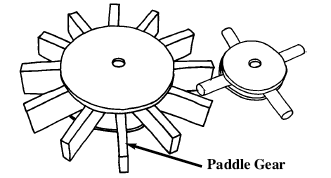
Parallel gears work in a similar way to In line gears, but are much easier to construct. The larger gear uses flat teeth while the driven gear uses dowels:
Designing
When designing and making gear wheels you need to apply a little common sense. For example, you need to consider the load or pressure put on the gears. Is the load small or great? When the load is small you can get away with things that would be impossible with a large load. In any case, you still have to follow some simple engineering guidelines and need to identify what you want to get from the gears. Here's a simple check list;- Do you want the gears to step up or step down? (speed up or slow down the performance).
- Do you want the gears to run parallel, or at an angle of 90° to change the direction of the drive?
- What size do you need to make them? (small space means making smaller gears and this can get tricky).
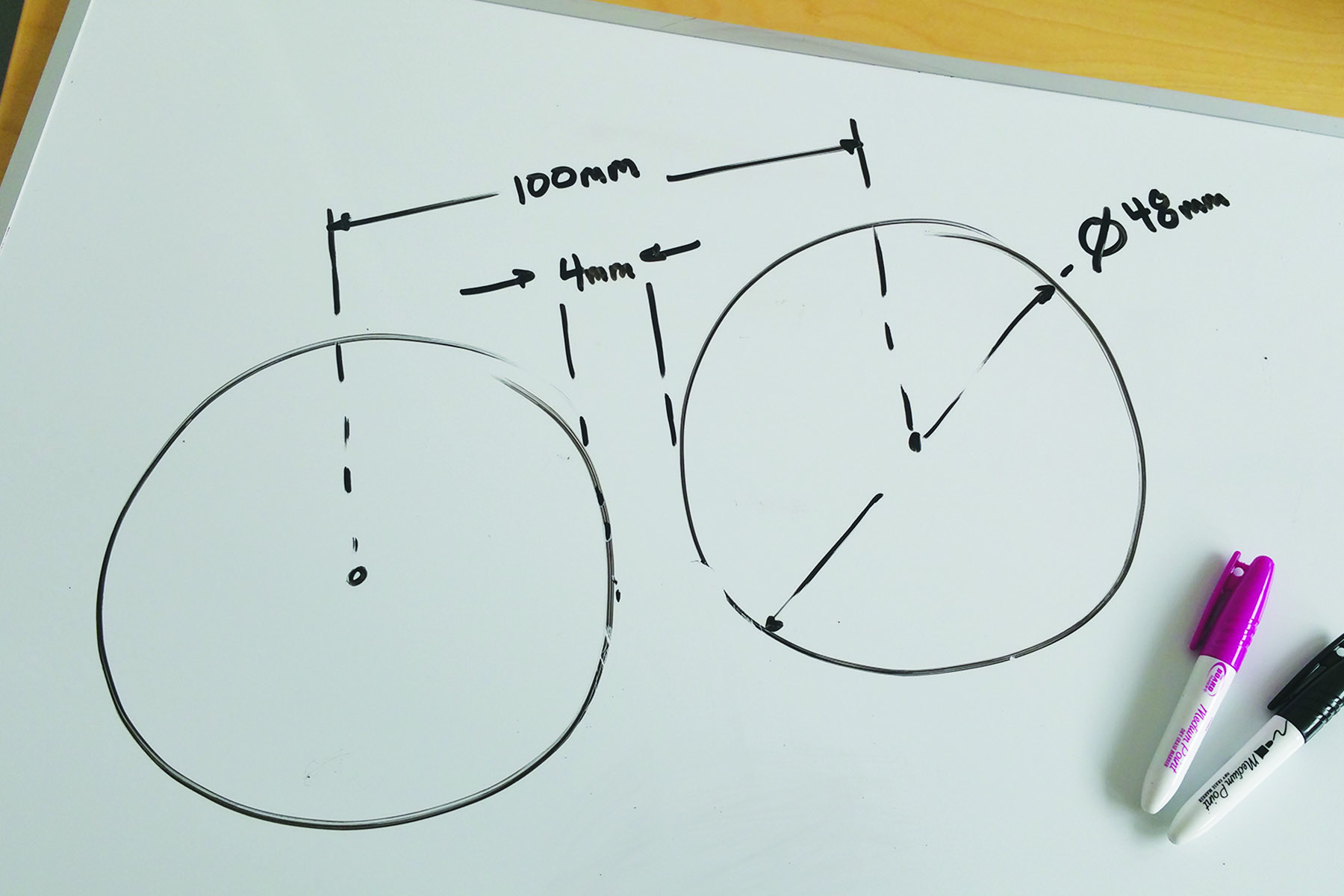
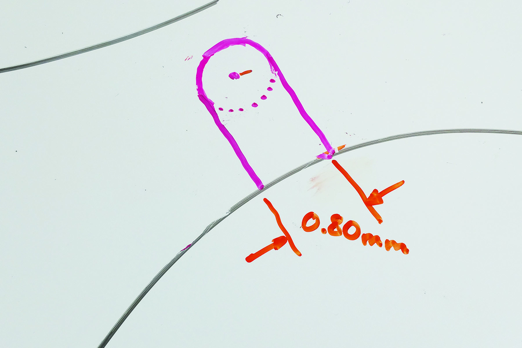
- Choose the inside diameters of the wheels leaving 4mm between the two circles. Measure from center of one circle to the center of the other:
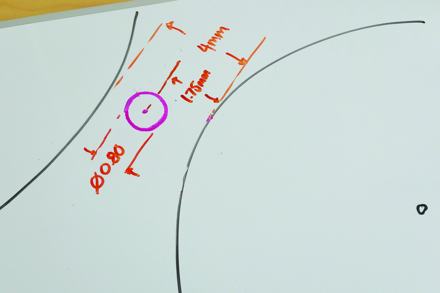
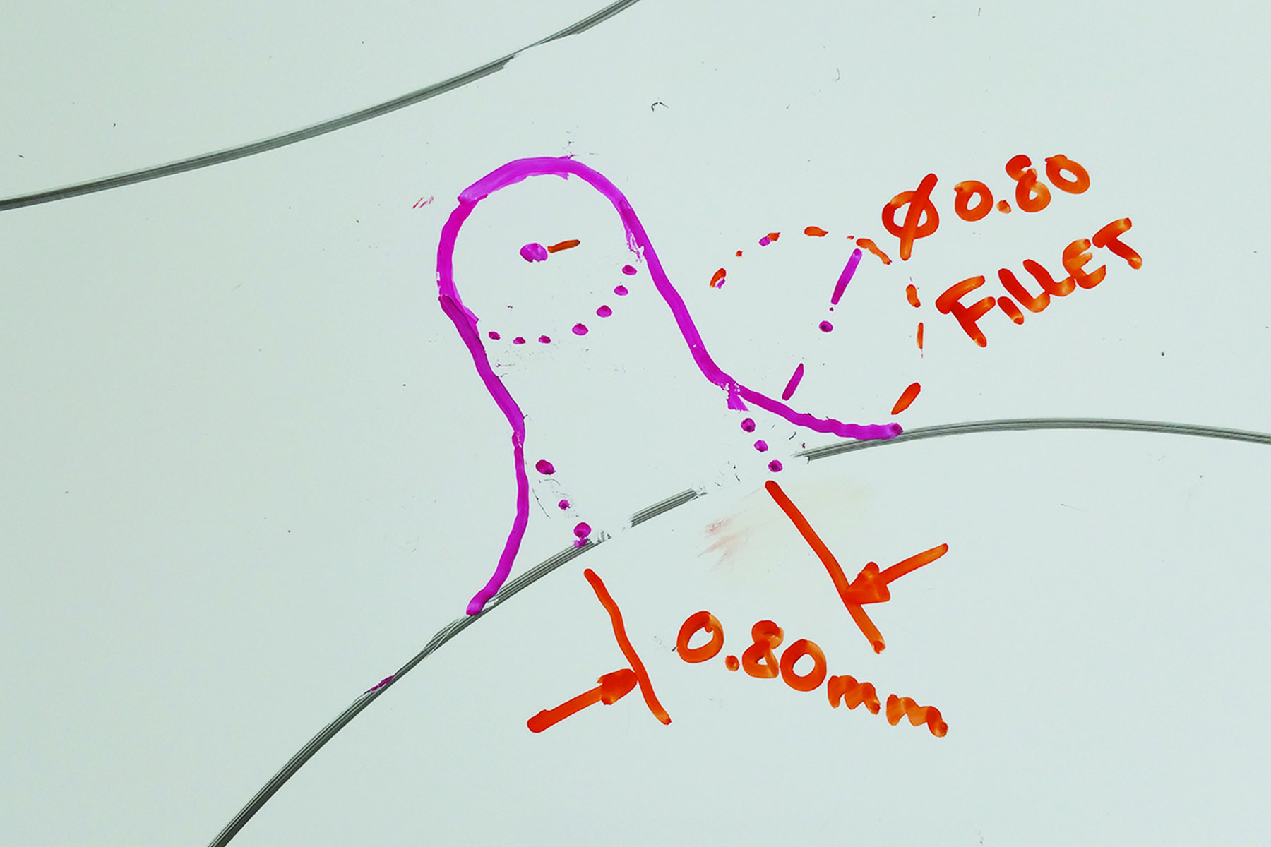
- You want to make the teeth 1.75mm away from the perimeters of the circles. Making the end of the tooth .8mm in diameter is the smallest diameter that prints reliably on the Ditto Pro. You can make this diameter larger to create a more robust gear:
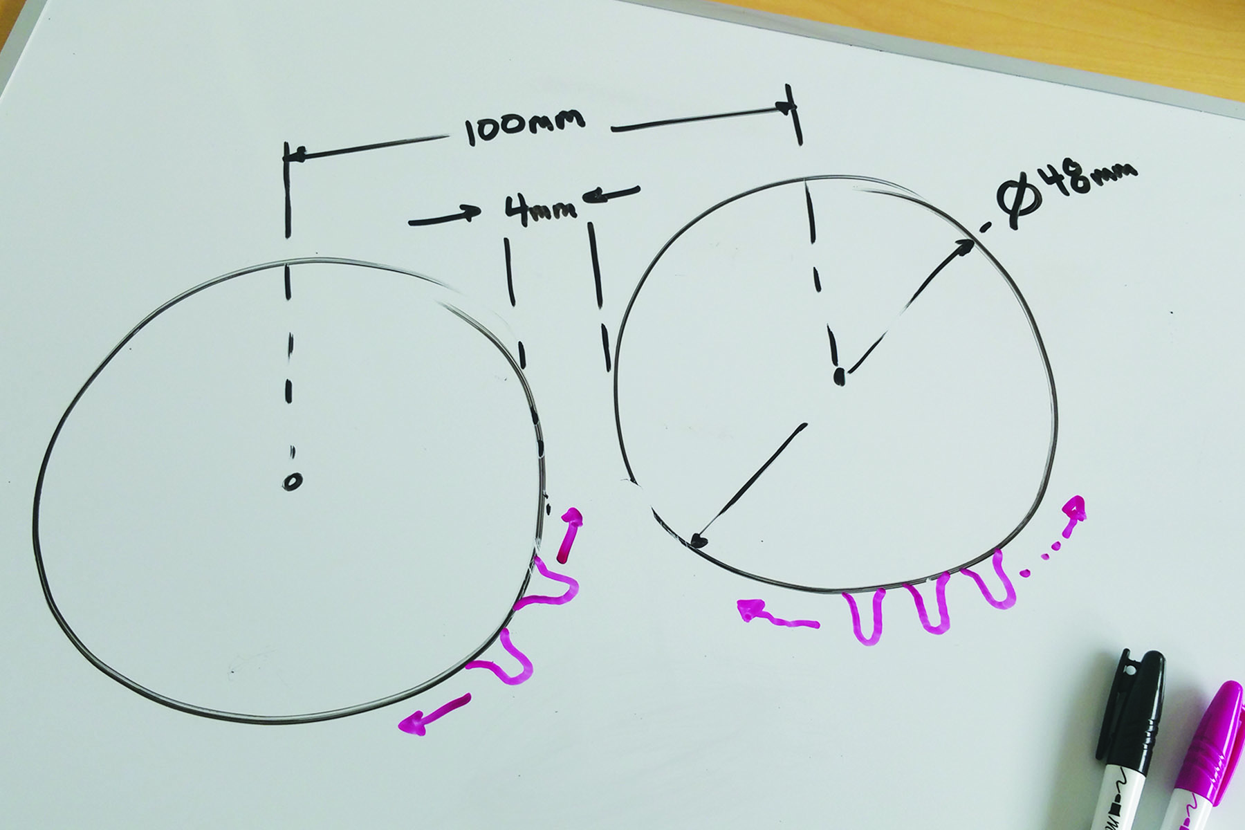
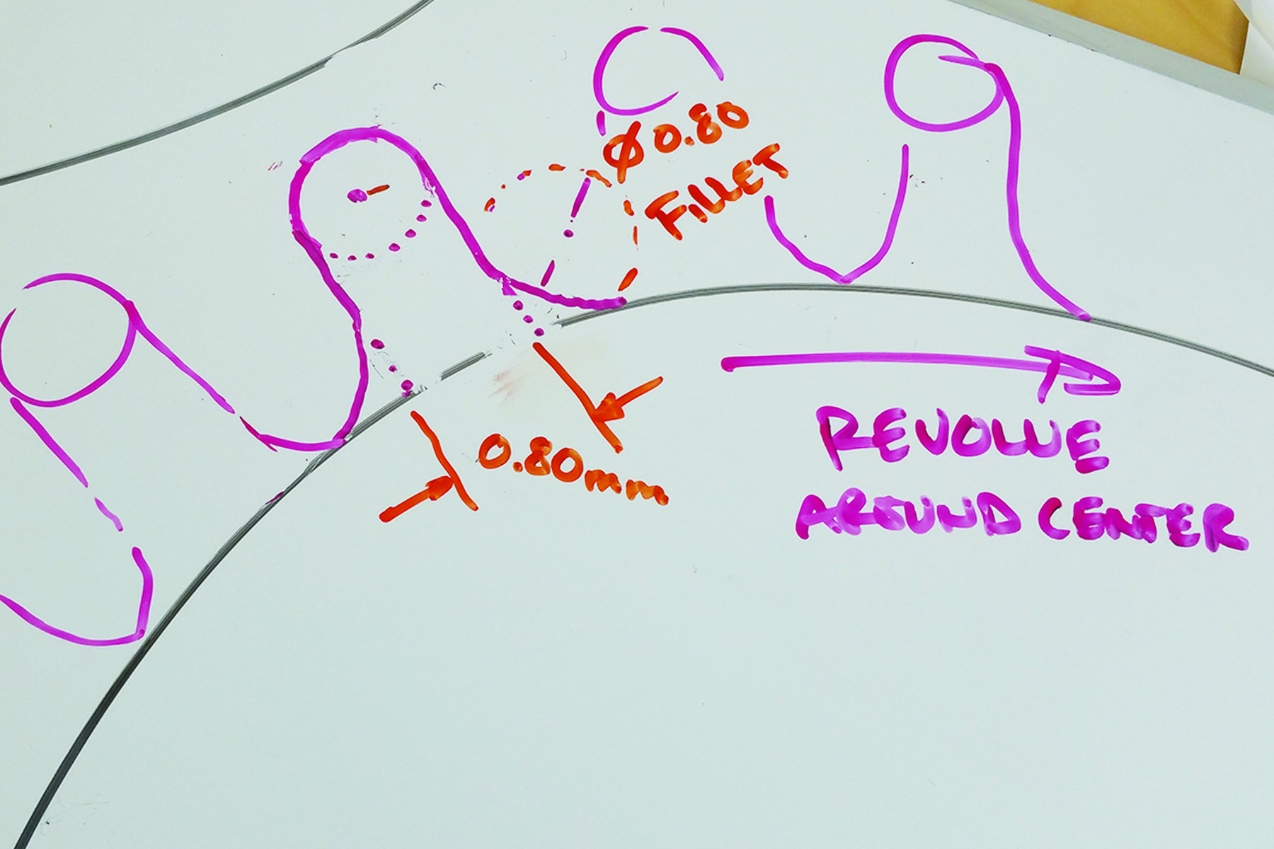
- Draw parallel lines from the tangents of the small circle to the larger circle:
- Create fillets where the parallel lines meet the larger circle:
- Revolve the teeth around the center of the large circle:
Vocabulary
Reflection Questions
How are gear teeth similar to levers?Designing Gears
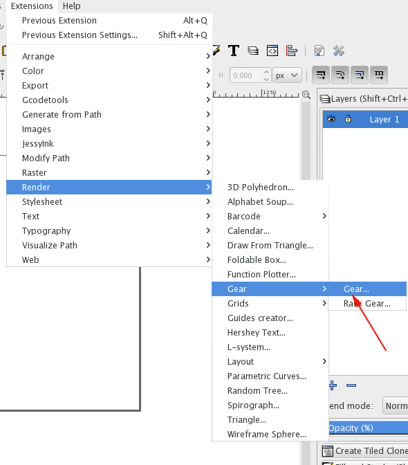
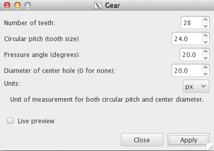
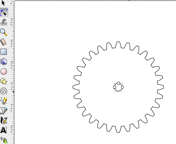
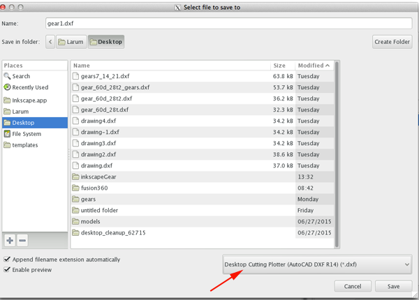
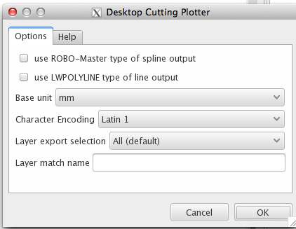
Paul Kaplan's Interactive Gear Generator. Create a gear and save the text output with an .svg extention.Gear Generator from Woodgears
Additional Resources
Connect It Gear Game from Engineering.comw Spur Gear Fitter Script by cbiffle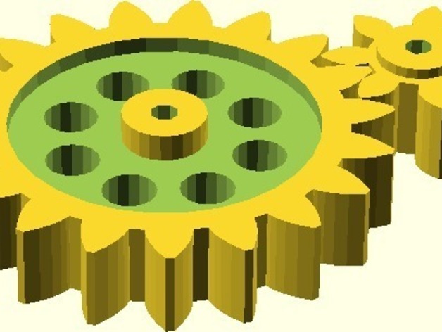
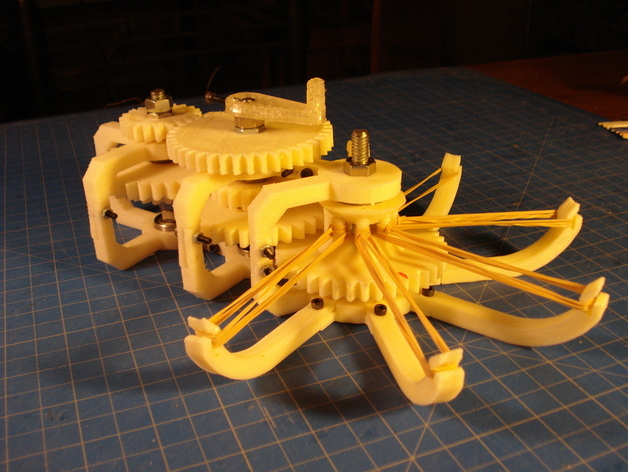
Rubber Band Gear Mechanism
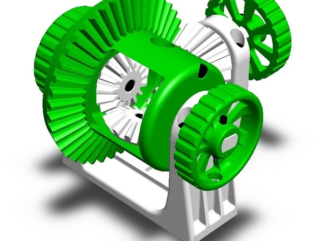
Functional Differential Gear System When two spur gears of different sizes mesh together, the larger gear is called a wheel, and the smaller gear is called a pinion. In a simple gear train of two spur gears, the input motion and force are applied to the driver gear. The output motion and force are transmitted by the driven gear. The driver gear rotates the driven gear without slipping. A rack and pinion mechanism is used to transform rotary motion into linear motion and vice versa. A round spur gear (the pinion), meshes with a spur gear which has teeth set in a straight line (the rack).