- Launch AutoCAD.
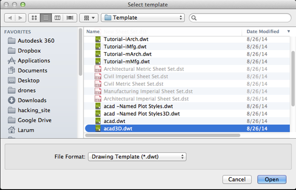
- Create a new drawing. Select File>New Drawing:
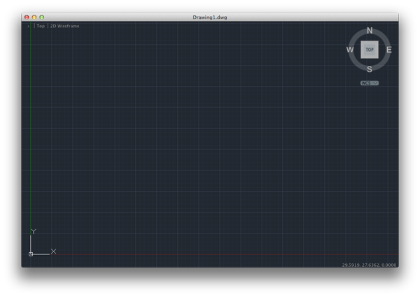
- Select acad3D.dwt template file and press the Open button to continue to the drawing screen.
- Find the commandline.
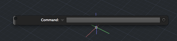
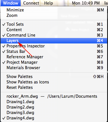
If it is not present you should be able to open it it by selecting Window> Command Line
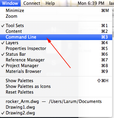
Other ways to display the command line are:
•
Pressing Command+3 on Mac, CTRL+9 on Windows.
• Pressing F2
•Typing COMMANDLINE or CLI
- You want to set your units to millimeters. Type UN and select UN (UNITS):
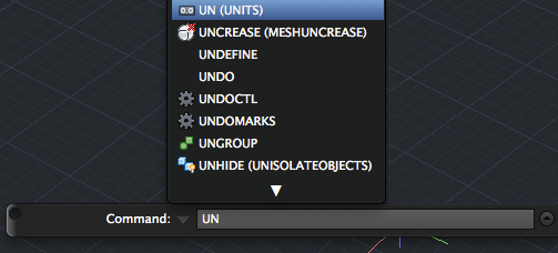
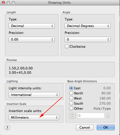
or select Format>Units from the top menu to bring up the Units Dialog box.
Set your units to millimeters:
 .
.
- You want to create a resolution appropriate for 3D printing. Type FACETRES and set it to 10.
- Make sure your profiles are not deleted after you use them. Type DELOBJ. Set the value to 0.
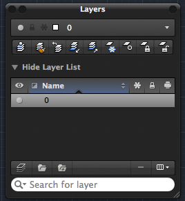
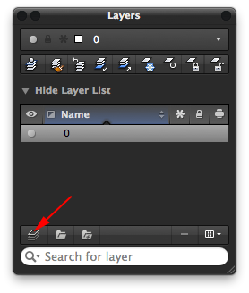
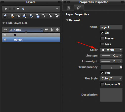
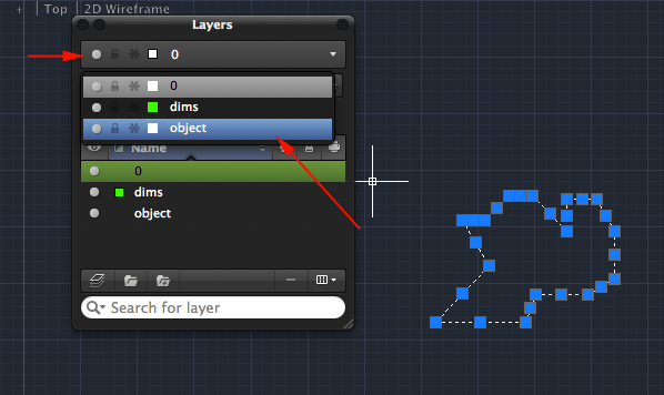
- Make new layers for Chassis, small pulley, large pulley and stoppers.
- To save your drawing type SAVEAS and save your drawing either in your work folder or on the desktop. Make sure to name your drawing so that you can find it later.
- Make the Chassis layer active.
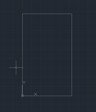
- You want to create a rectangle 66 x 110 mmm.
Type RECT for rectangle and press RETURN.
Set the starting point to 0,0 by typing 0,0 and pressing RETURN.
Set the next corner to 66, 110 by typing 66,110 and pressing RETURN.
- Type Z and press RETURN then type E and press RETURN to Zoom Extents
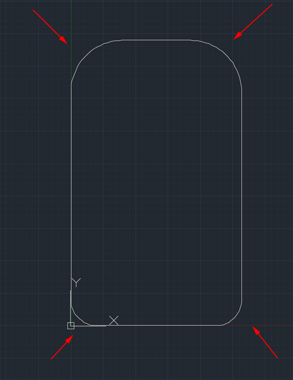
- You want to round the corners.
Type FILLET and press RETURN.
Then type R for Radius and press RETURN. You want a radius of at least 10. Press RETURN.
Type M for Multiple and press RETURN.
- Click on the left side of the rectangle near the top and the top of the rectangle near the left side. Continue for all corners. Feel free to change the FILLET values between the front and back of the chassis.
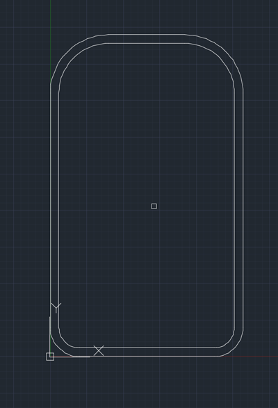
- Type OFFSET and press RETURN.
Type 3 and press RETURN.
Click on the outline of the chassis to select it then click inside the outline:
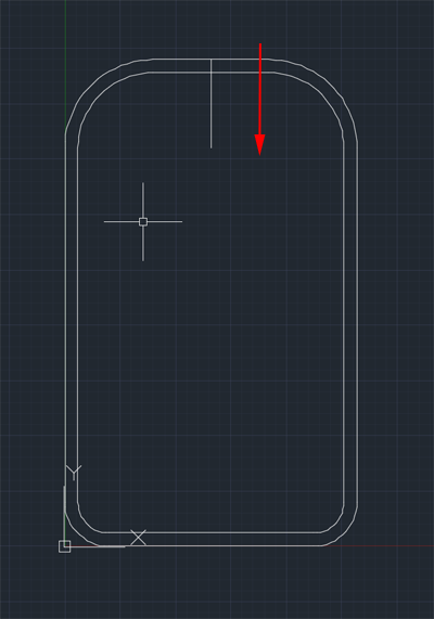
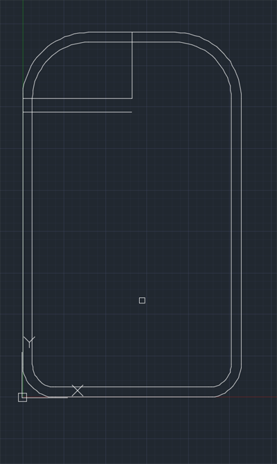
- Type L for LINE and press RETURN.
Click on the midpoint of the top of the chassis to set the first point. Click to accept.
Type @0,-20 press RETURN.
Press RETURN again to end the line.
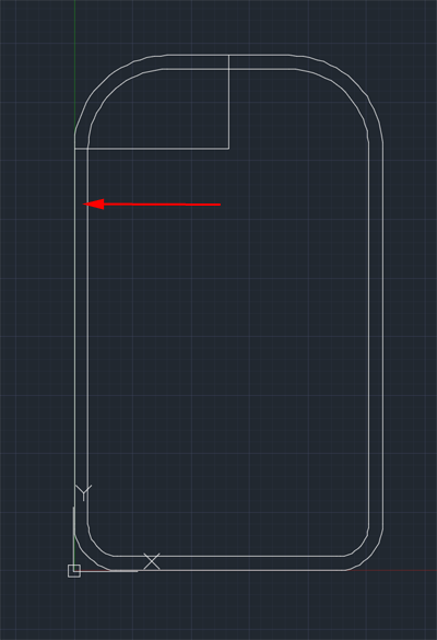
- Type L again and press RETURN.
Set the first point to the end of the line you just drew. Click on the point.
 Set the end of the line to where it intersects the frame (You made need to check that the intersect OSNAP is enabled). Click and press RETURN to end the line.
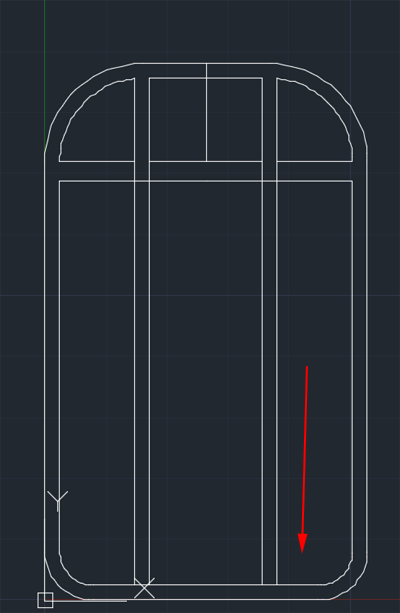
- Type OFFSET and press RETURN.
Type 4 and press RETURN.
Click on the horizontal line you just drew to select it then click below it:
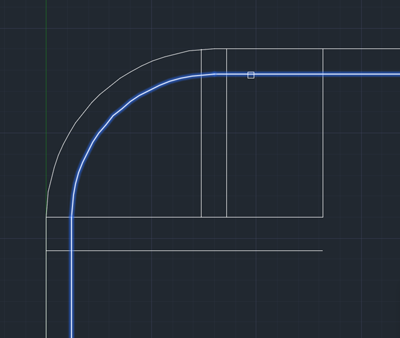
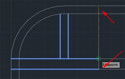
- Type L for LINE and press RETURN.
Click on the point where the curve of the top right fillet becomes straight to set the first point.
 Click on the intersection of the top horizontal line below the fillet and press RETURN to end the line.
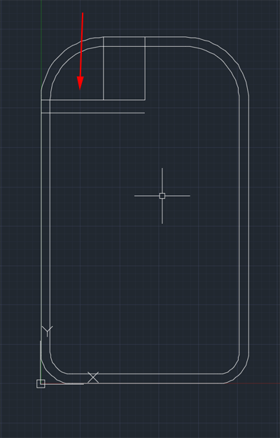
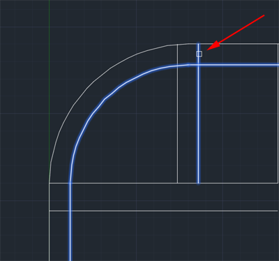
- Type OFFSET and press RETURN.
Type 1.5 and press RETURN.
Click on the vertical line you just drew to select it then click on both sides of it:
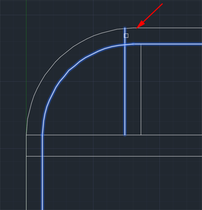
- Select the center line and delete it:
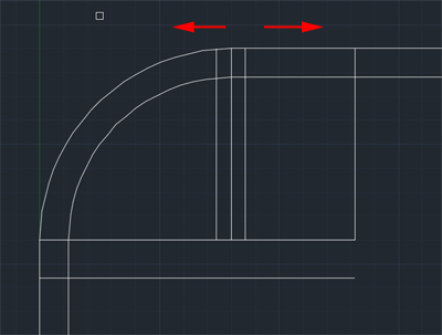
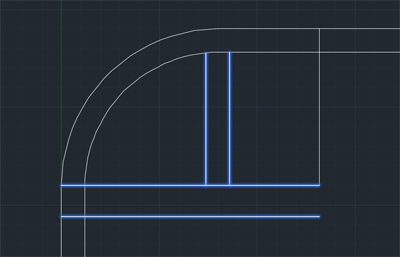
- Type TR for TRIM and press RETURN.
Click on the inner outline and press RETURN.
 Click on the horizontal lines between the outlines to remove them.
Press RETURN to stop trimming:
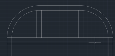
- Type MIRROR and press RETURN.
Select the two vertical lines and the 2 horizontal lines and press RETURN.
Click on top of the midpoint of the chassis and then on the bottom of the vertical line drawn from that point. Press RETURN.
Press RETURN again:
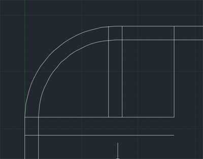
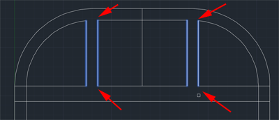
- Type TR and press RETURN.
Click on the four vertical lines and press RETURN.
Click on the segments between the tops and bottoms to remove. Press RETURN:
- Trim the left and right side:
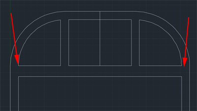
- Type EXTEND and press RETURN.
Click on the bottom inner outline of the chassis and press RETURN.
Click the four vertical lines.
Press RETURN to end:
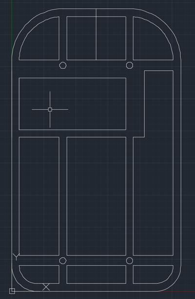
- Draw this horizontal line.
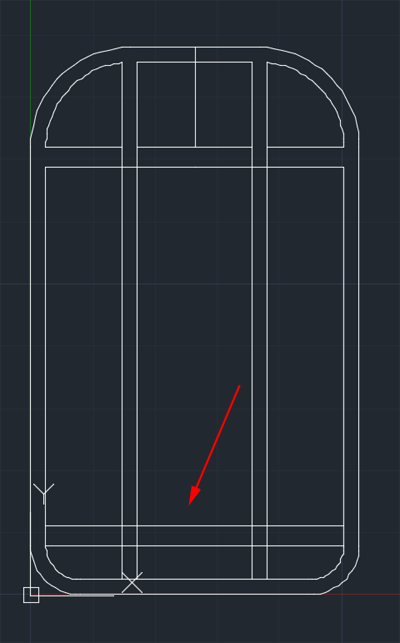
- Use OFFSET to make another line 4mm away:
- Use TRIM to clean up the drawing:
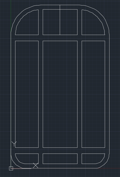
- Use L to draw these lines:
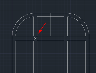
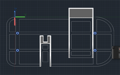
- Type C for CIRCLE and press RETURN.
Click on the intersection of the lines and press RETURN.
Type D and press RETURN.
Type 2.5 and press RETURN:
- Use MIRROR to place the four circles:
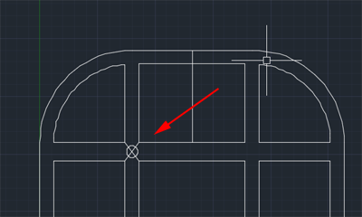
- Delete the crossing lines.
- The 9V matter is 25.5 mm wide and 16.25 high and 50.5 long (with the connector. Keep in mind that your walls will have thickness. If your wall is .8mm thick add that value to your length.
You need to make a space .4mm larger on each side to hold the battery, and then add .8 to every edge that will have a wall.
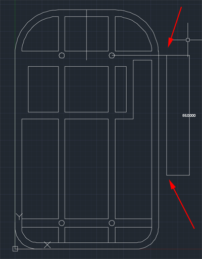
- Your pulleys should be about 55mm away from each other. Use LINE to sketch out the distances.
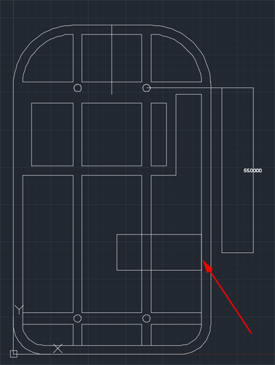
- Your motor dimensions are 27.2mm long, 10 wide and 12.05 deep. You need to add .4 to all dimensions and then add .8 to every edge that will have a wall.
- Center the rectangle:
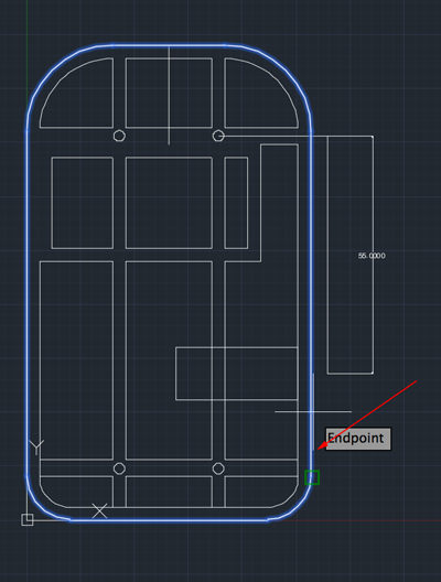
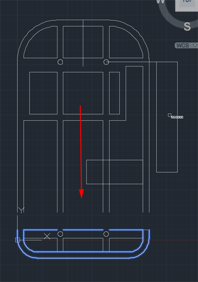
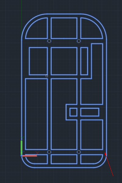
- Maybe I want a longer chassis? If you do as well, type BREAK and press RETURN.
Click on the outer outline.
Type F for first and press RETURN.
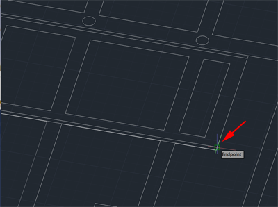
Click where you want to break and then
type @ and press RETURN.
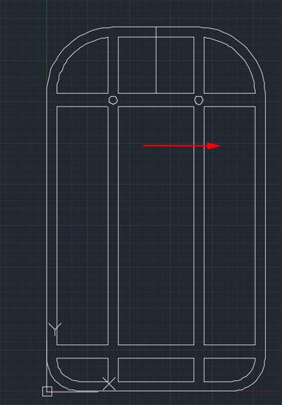
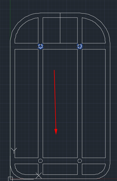
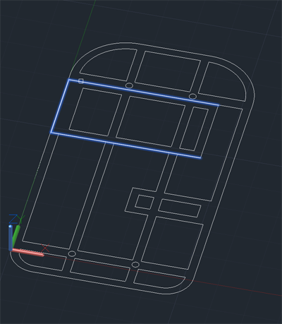
- Select the lines and move them to where you want them:
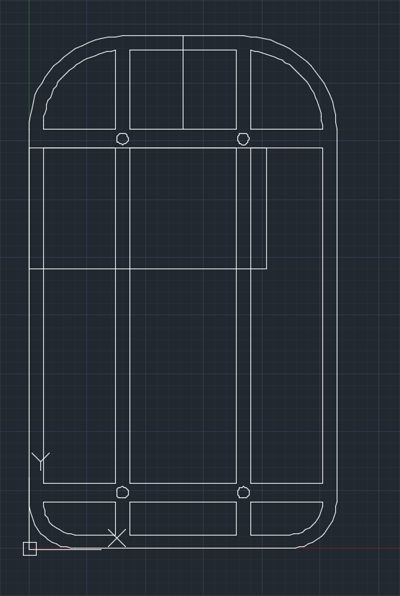
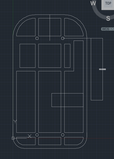
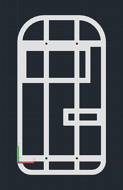
- Delete the extra lines and use EXTEND and TRIM to complete the shape:
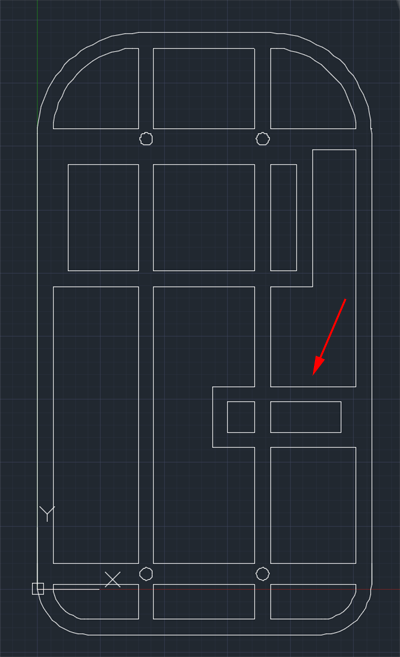
- Add an OFFSET of 3 to your motor rectangle:
- Use TRIM to clean up the drawing:
- Delete the center line and the dimension lines
:
 /li>
/li>
-
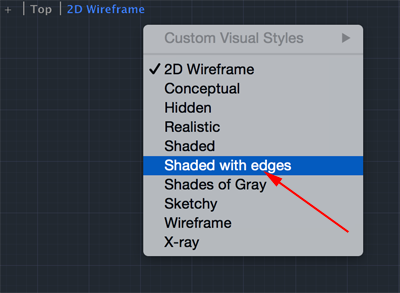
Type VS for VSCURRENT and press RETURN.
Type S for Shaded with Edges and press RETURN.
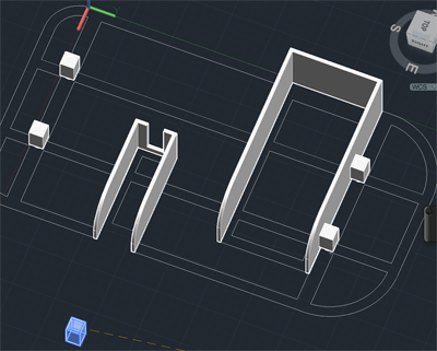
- Type PRESSPULL and press RETURN.
Move mouse over shape until everything is highlighted and type RETURN.
Type 2 and press RETURN:
- CTRL+ click on the work area. Select Isolate>Hide Objects. Select the chassis.
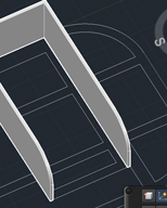
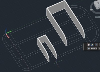
- Add the walls around the battery and the motor. Use PLINE to create polylines that can be offset. Make your walls .8mm thick (use OFFSET). Make the battery walls 18.5mm high:
Fillet the edge with FILLETEDGE:
- Make the walls for the motor. They should be 14.4 high. Fillet the edges:
- Make a box that is 1 mm thick, 5 mm wide and 12.4 mm high:
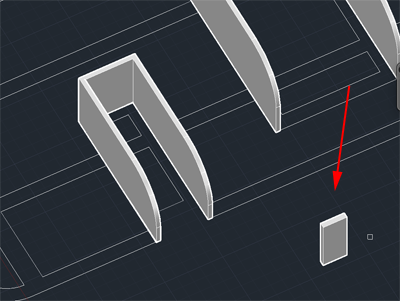
- Move the box so the center is aligned with the motor's back wall:
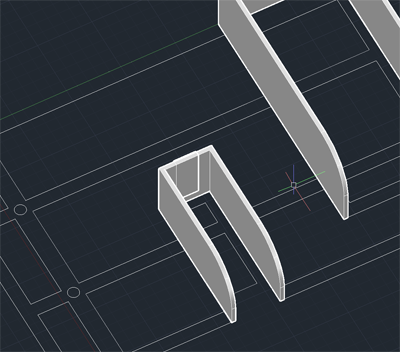
- Subtract the box from the wall:
Type SUBTRACT and press RETURN.
Click on the back wall and press RETURN.
Click on the box and press RETURN.
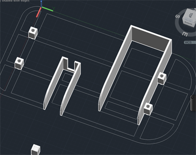
- Type REGION and press RETURN.
Select all the circles and type RETURN:
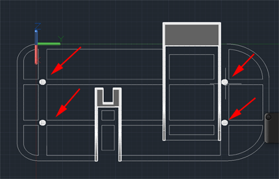
- Type EXTRUDE and press RETURN.
Click on a circle and press RETURN.
Type 8.6 and press RETURN.
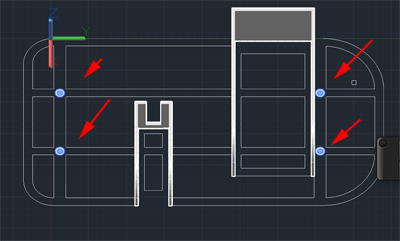
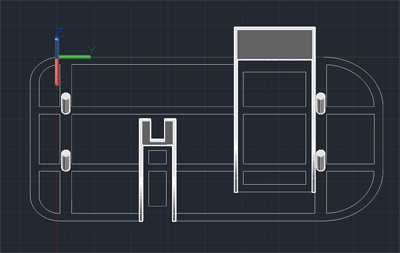
- Create a box 4x4x6.6 and move copies so that their centers align with the top centers of the cylinders.
- Subtract the cylinders from the boxes.
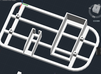
- CTRL+ click on the work area and click on Isolate>End Object Isolation.
- Export your chassis.
Small Pulley
- Type CONE and press RETURN.
Set the base Diameter to 17.4.
Set the Top radius to 6.88.
Set the height to 1.7.
- Type Cylinder and press RETURN.
Set the starting point to be the center of the top of the cone.
Set the radius to 6.88.
Set the height to 3.
- Make a copy of the bottom cone and move it to the side.
- Type 3DROTATE and press RETURN.
Click on an axis and type 180 in order to rotate the disk 180 degrees.
- Type M for MOVE and press RETURN.
Select the flipped disk. Set the bottom center to the top center of the cylinder.
- Create another cylinder with the diameter 3.4.
Set the height to 12.
- Use MOVE to center the cylinder with the stack of cones and cylinder.
- Subtract the tall cylinder from the group.
- Export
Large Pulley
- Type CONE and press RETURN.
Set the base Diameter to 34.8.
Set the Top radius to 13.76.
Set the height to 1.7.
- Type Cylinder and press RETURN.
Set the starting point to be the center of the top of the cone.
Set the radius to 13.76.
Set the height to 3.
- Make a copy of the bottom cone and move it to the side.
- Type 3DROTATE and press RETURN.
Click on an axis and type 180 in order to rotate the disk 180 degrees.
- Type M for MOVE and press RETURN.
Select the flipped disk. Set the bottom center to the top center of the cylinder.
- Create another cylinder with the diameter 3.4.
Set the height to 12.
- Use MOVE to center the cylinder with the stack of cones and cylinder.
- Subtract the tall cylinder from the group.
- Export
Wheels
Wheels need to have a diameter greater than the large pulley and a wall thickness of .8mm. There should be a central cylinder for the axel to fit snuggly on. This central cylinder should be slightly higher than the wheel.
Stoppers
Stoppers fit over the axel and keep the wheels in there proper place. Keep them small.