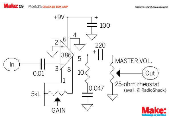
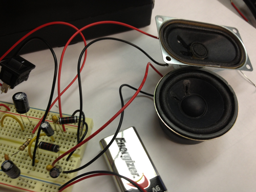
The Amplifier takes an electrical signal and makes the signal stronger, and in the end, louder. Because the signal is strengthened by an amplifier, you can play music through higher resistant speakers. This amplifier is a solid-state-hi-gain design and is intended to run through an 8 ohm speaker. The amplifier schematic was originally designed by Ed Vogel and Blind Lightnin' Pete from MAKE Magazine.
The heart of the circuit is the operational amplifiers, or op amp. The op amp is an IC that produces an output voltage hundreds of thousands of times larger than the voltage difference between its input terminals:
Vout=AOL(V+-V-)
Where V+ is the voltage at the non-inverting terminal, V- is the voltage at the inverting terminal and AOL is the open-loop gain of the amplifier (the term "open-loop" refers to the absence of a feedback loop from the output to the input).
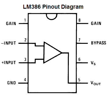
The LM386 is a popular audio amplifier chip that allows a user to amplify sound.
The gain control of the amplifier. You can adjust the gain by connecting a variable resistor, like a potentiometer, a resistor and capacitor or just capacitor between these terminals.
2 and 3:
The sound input signal terminals. These are the terminals where you place the sound which you want amplified. Terminal 2 is the -input and Terminal 3 is the +input.
4:
GND (ground)
5:
The output of the amplifier. This is the terminal in which the amplified sound signal comes out.
6:
The terminal which receives the positive DC voltage so that the op amp can receive the power it needs to amplify signals.
7:
The Bypass terminal. This pin is usually left open or is wired to ground. However, for better stability, you can add a 10µF capacitor to prevent oscillations in the op amp chip.
The LM386 takes anywhere from 4-12 volts of DC voltage to operate.
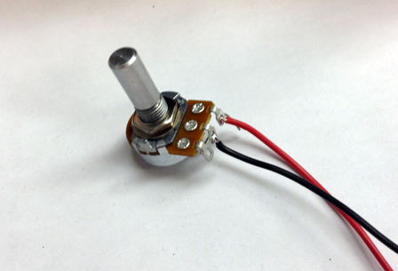
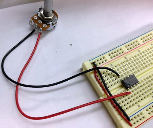
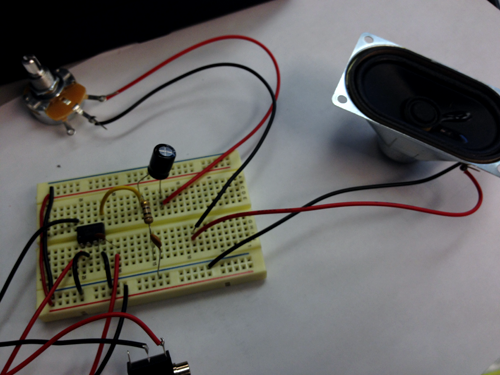
Solder a red wire to the third lead of the 5K potentiometer and a black to the center lead:
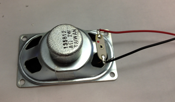
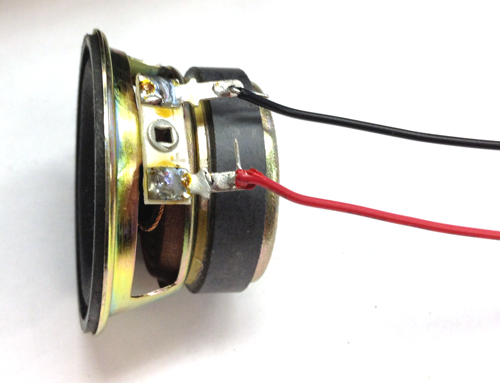
Solder red and black wires onto the appropriate leads of the treble speaker:
Solder red and black wires onto the appropriate leads of the bass speaker
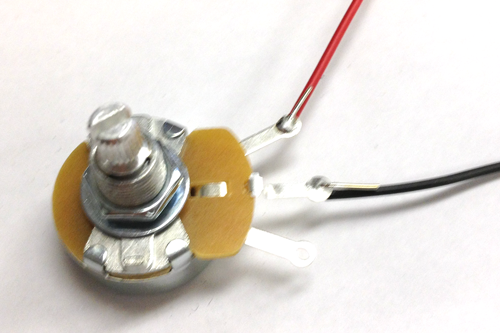
Solder a red wire the the third lead of the Rheostat and a black wire to the center lead:
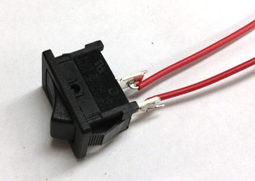
Solder two wires to the leads of the switch:
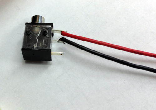
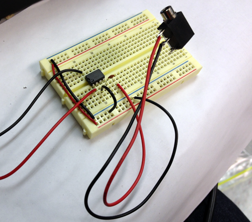
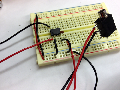
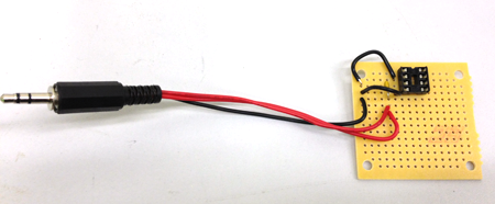
Solder a red wire to the first lead of the Audio Jack and a black wire to the second:
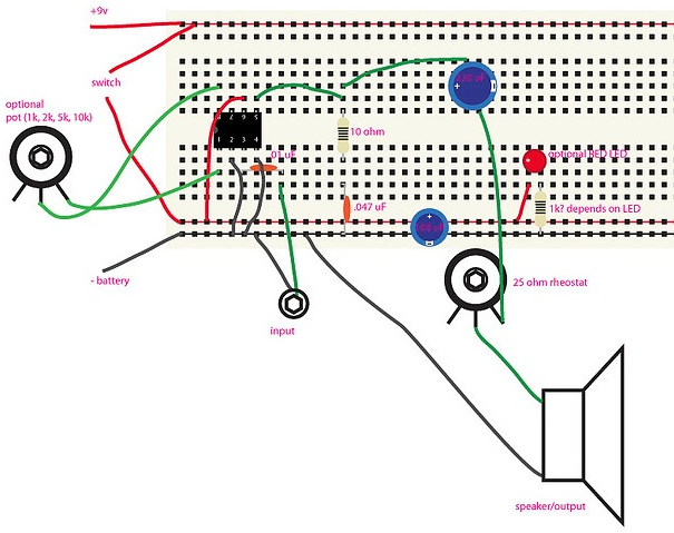
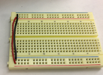
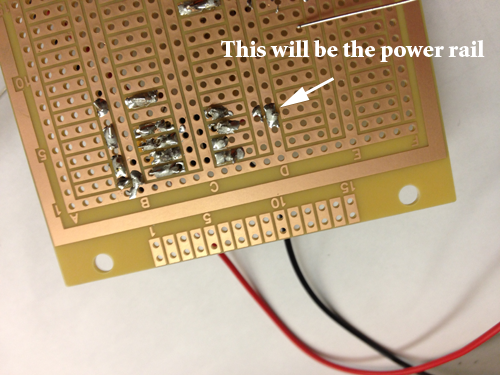
Take two wires and connect power to power and ground to ground so that when you power the breadboard you will be able to use both power rails as power and ground:
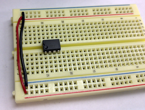
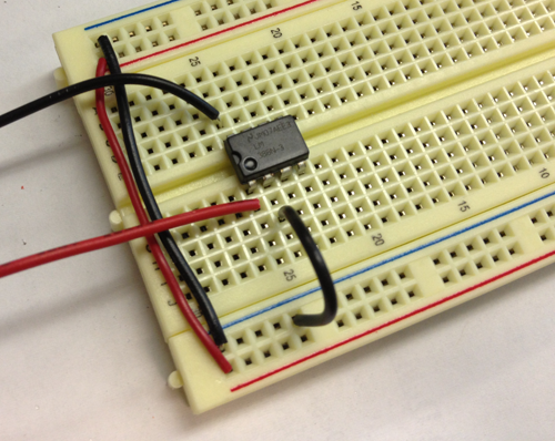
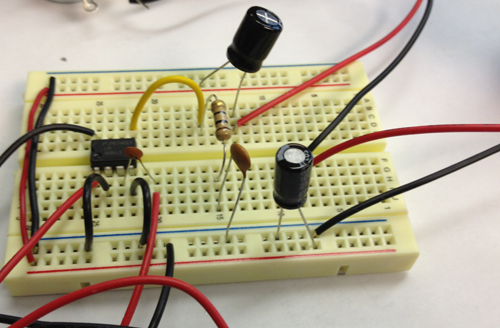
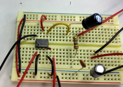
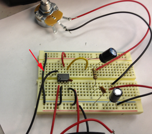
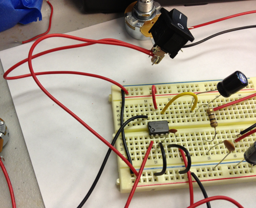
Insert the LM386 chip over the gutter of your breadboard. Make sure that the circle is facing in the same direction as you see in the image. The pin closest to the circle is pin 1. On the same side are pins2-4. On the other side of the chip on a diagonal from pin 1 and across from pin 4 is pin 5. The pin at the top of the chip across from pin 1 is pin 8:
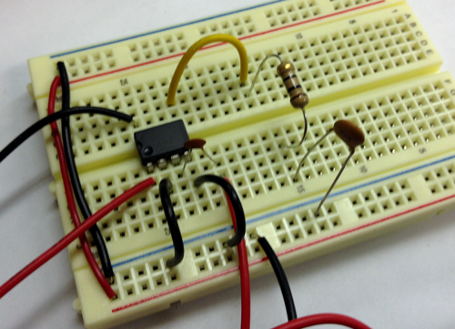
Connect the red lead of the potentiometer to pin 1 and the black lead to pin 8. This potentiometer will control the volume:
Use a wire to connect pin 2 to a GND rail:
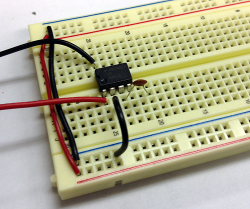
Connect pin 3 to a row on the breadboard with the .01µF capacitor:
Connect the other side of the capacitor to the red lead of the audio jack and the black lead to the GND rail
Connect pin 4 to the GND rail:
Connect pin 5 to a row on the breadboard and that row to the 10ohm resistor. Connect the resistor to GND trough the 47n capacitor:
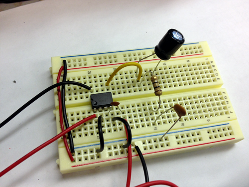
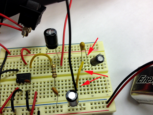
Add the 220µF Capacitor (the long lead) to the same row that is connected to pin 5:
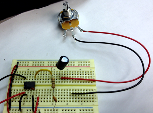
Connect the red wire of Rheostat to the short lead of the 220µF Capacitor and the black wire to a row on the breadboard:
Connect the red wire of a speaker to the black wire of the Rheostat and the black wire of the speaker to the GND rail:
Connect Power and GND through the 100µF capacitor:
Remove thee red wire that connects power to power:
Connect the two wires of the switch to the power rails
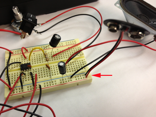
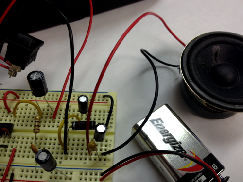
Connect the 9V battery connector to the board:
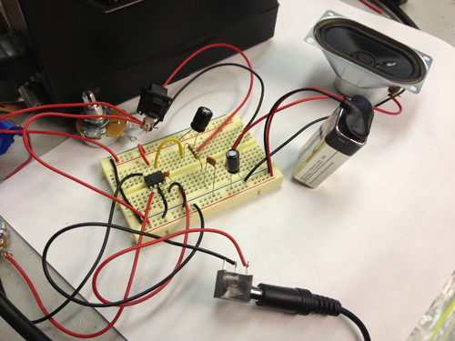
Attach the battery, and connect an iphone to the circuit to test:
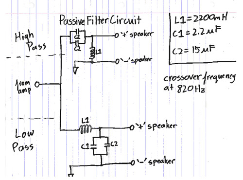
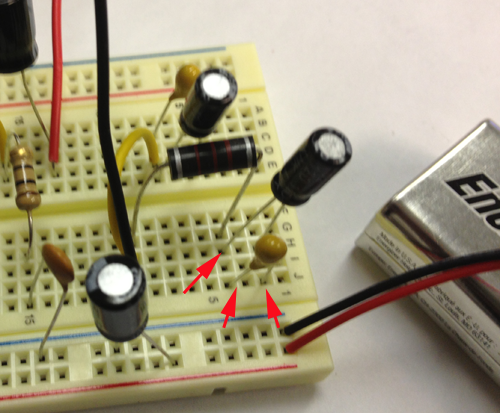
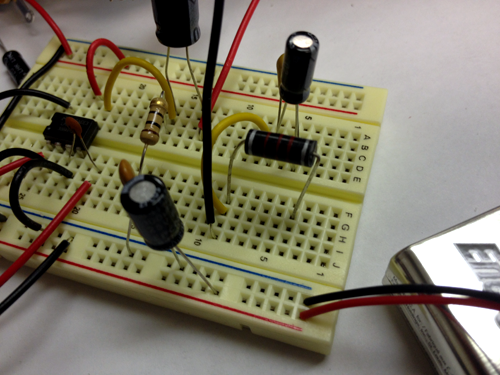
If all works replace the speaker with a wire connected to the long leads of the 2.2µF and the 22µF capacitors
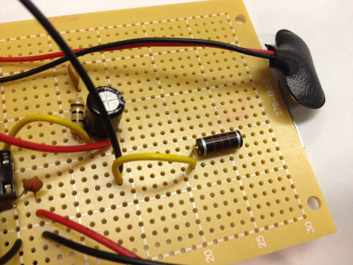
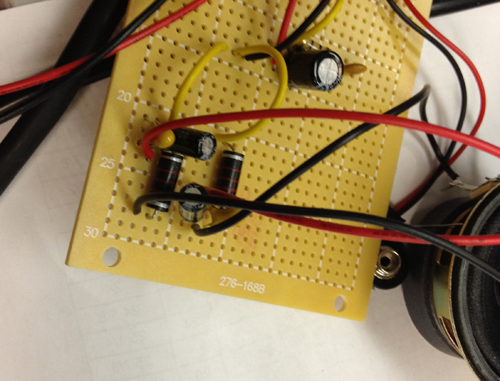
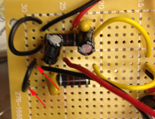
Connect the choke to the same place where the red wire of the speaker wire was:
Connect the other side of the choke to the long leads of the other 2.2µF and the 22µF capacitors:
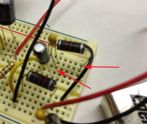
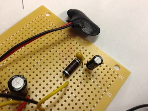
Connect the red wire of the bass speaker to the end of the choke connected to the long leads of the other 2.2µF and the 22µF capacitors. Connect the black wire to the short leads of the capacitors:
Connect the other choke to the short leads of the first capacitor pair:
Connect the red wire of the treble speaker to where the choke is connected to the 2 capacitors. Connect the black lead to the other side of the choke:
Connect the black wires of both speakers to the GND rail through a wire:
Test the circuit again
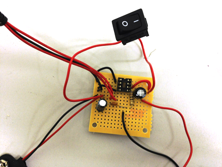
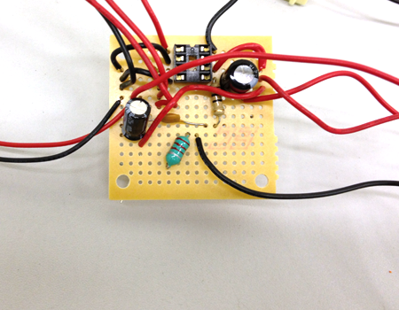
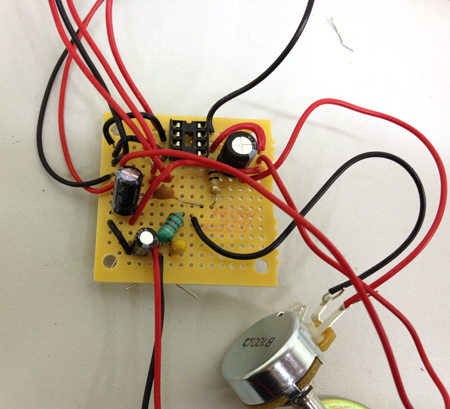
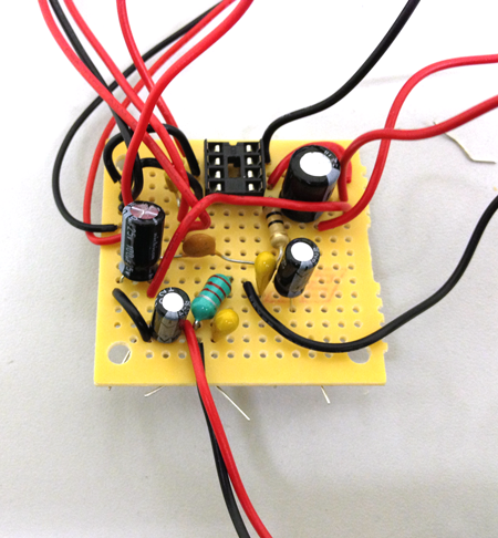
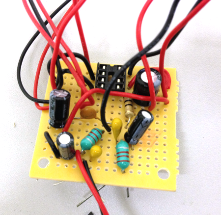
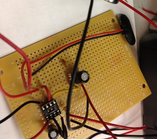
Freeform solder or use the protoboard to make your design more permanent
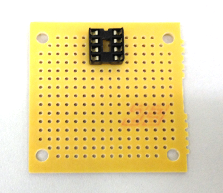
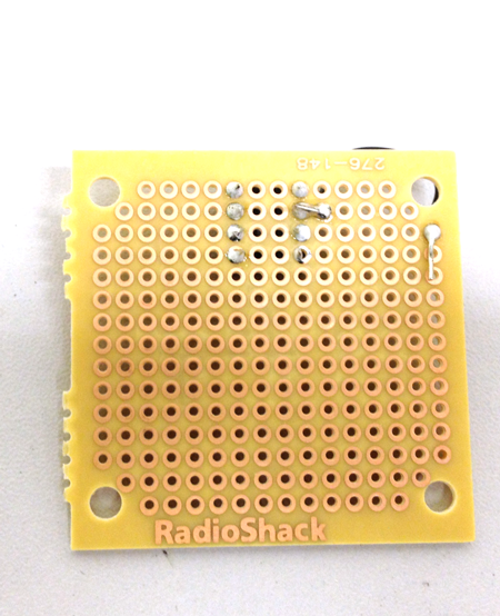
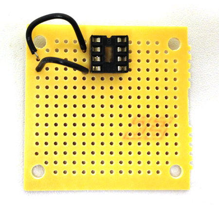
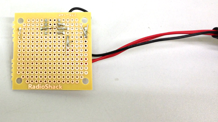
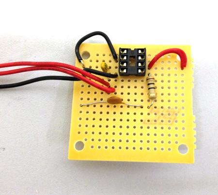
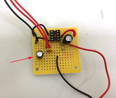
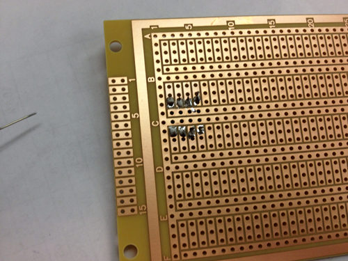
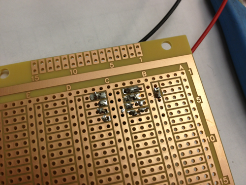
Place the socket in the board and solder into place:
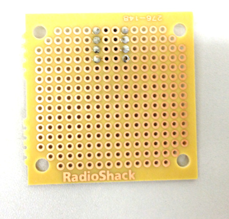
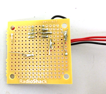
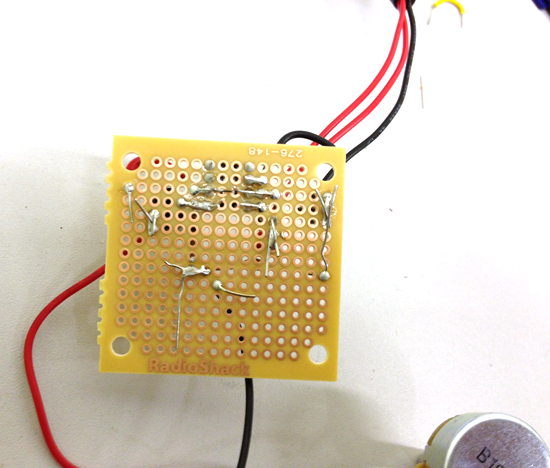
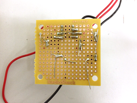
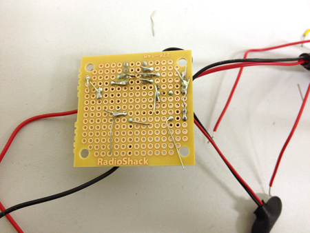
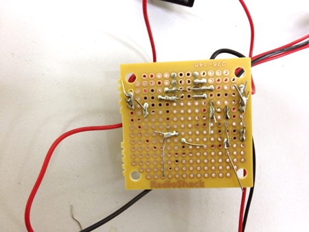
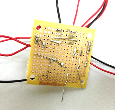
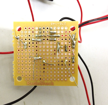
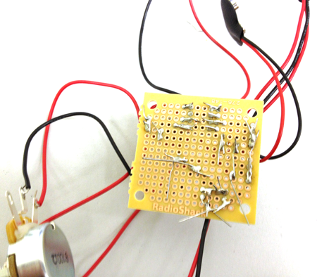
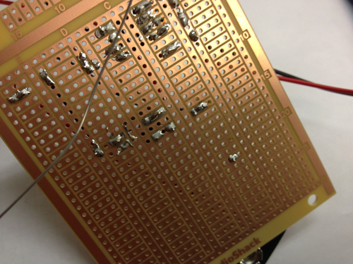
Here is the back.
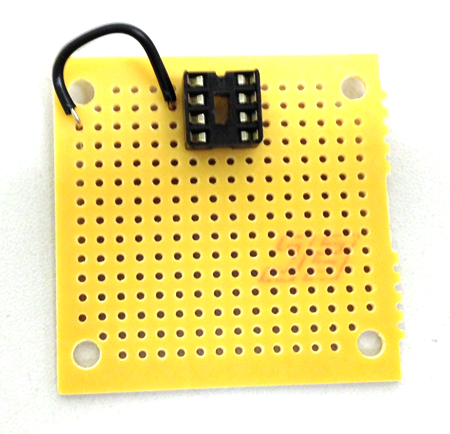
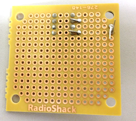
Connect pin 2 to the left side of the board. This will become the GND side:
Here is the back.
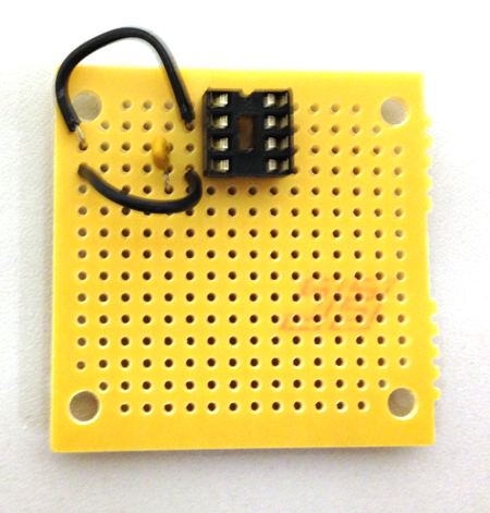
Connect pin 4 to the left side of the board.
Here is the back.
Connect pin 3 to the capacitor 0.01µF:
Connect the other side of the capacitor to the two red inputs and the gnd input to the left side of the board:
Here is the back.
Connect pin 5 to one side of the 10Ω resistor:
Here is the back.
Connect pin 5 to the 220 capacitor:
Here is the back.
Connect the other side of the resistor to the .47 capacitor and the other side of the capacitor to the left side:
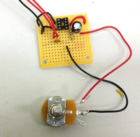
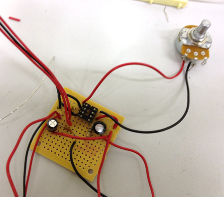
Connect the rheostat to the 220µF capacitor:
Here is the back.
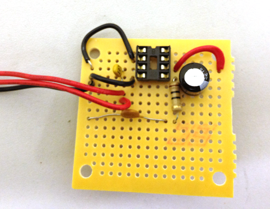
Add the 100µF capacitor so that the short lead is on the left side:
Here is the back.
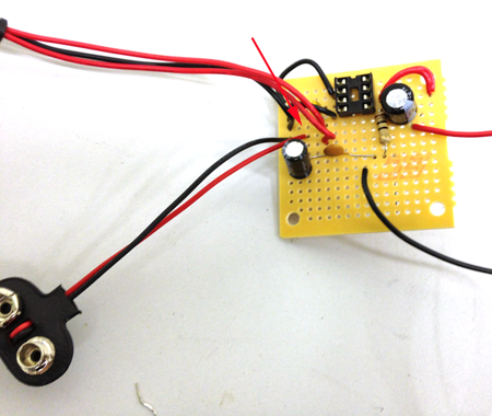
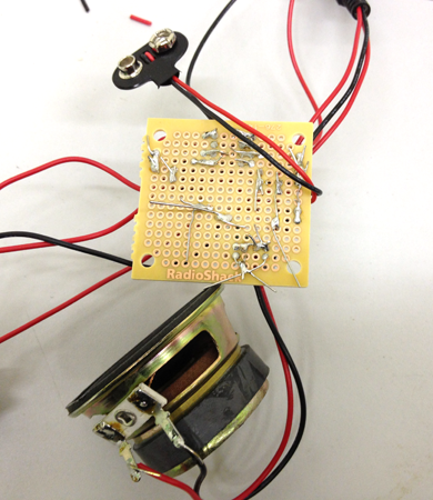
Connect the battery clip:
Here is the back.
Connect the switch:
Here is the back.
Connect the 5K potentiometer between pis 1 and 8:
If you are adding the filters, add the choke off of the rheostat:
Here is the back.
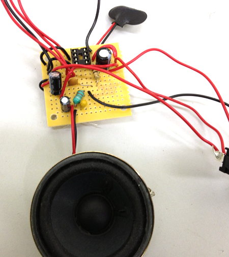
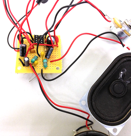
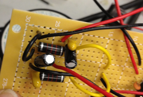
Add the capacitors and the bass speaker:
Here is the back.
Connect the speaker to the left side:
Here is the back.
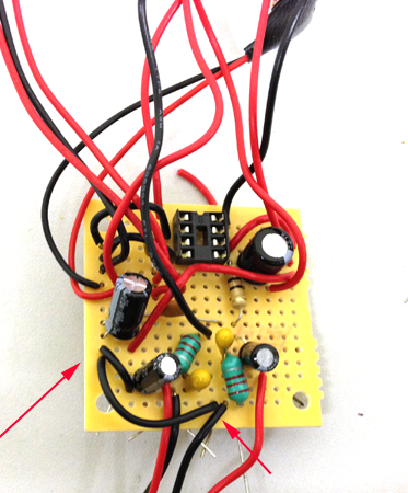
Add the second filter. Start with the capacitors:
Here is the back.
Add the second choke:
Add the treble speaker:
Connect the speaker to gnd:
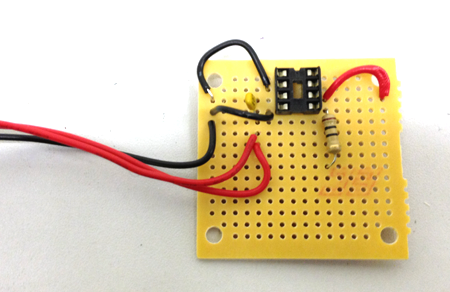
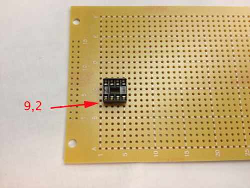
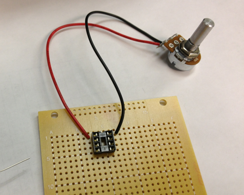
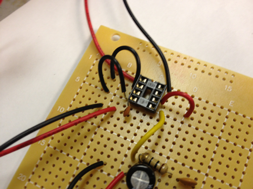
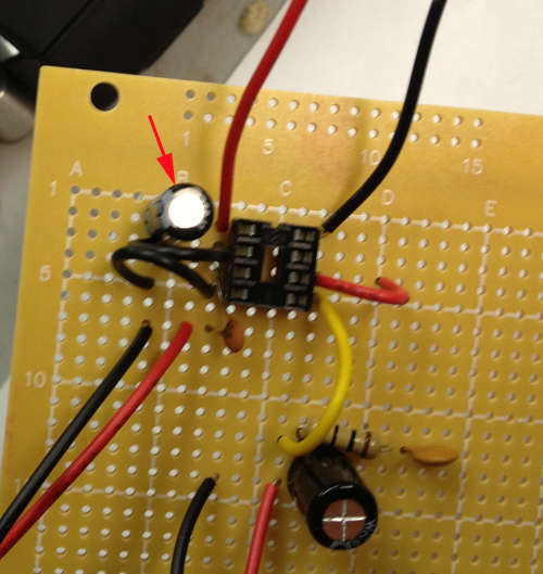
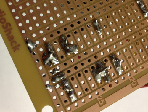
Place the 8 pin socket in the protoboard so that pin 1 is 9 columns across and 2 rows down:
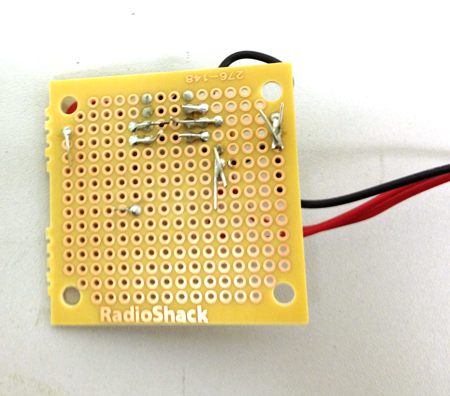
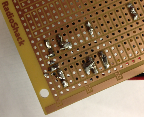
Here is the back. Be careful to not connect the rows to each other with solder:
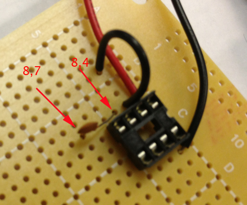
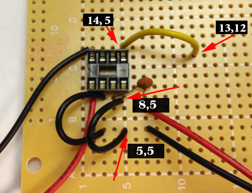
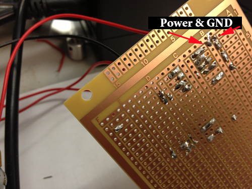
Solder the red wire to hole (8,2) and the black wire to (14,2):
Here is the back:
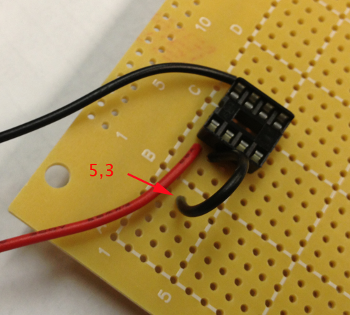
Solder a wire from (8,3) to (5,3):
Here is the back:
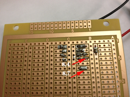
Connect (8,4) to (8,7) with the .01µF capacitor:
Here is the back:
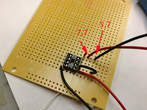
Connect the red wire of the input to (7,7) and the black wire to (5,7)
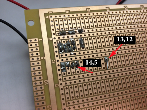
Connect (14, 5) to (13, 12) and connect pin 4 to GND (8, 5 to 5,5)
Here is the back:
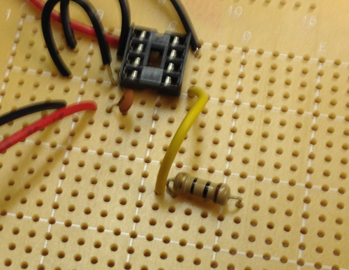
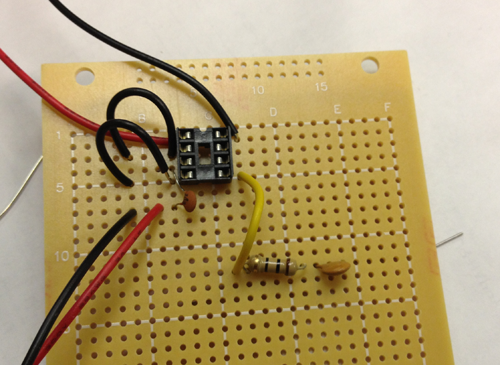
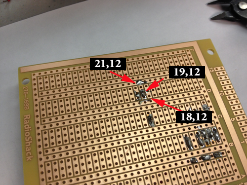
Solder the resistor to pin (14,12) and (18,12):
Solder the 47n capacitor to (19, 12) and (21,12):
Here is the back:
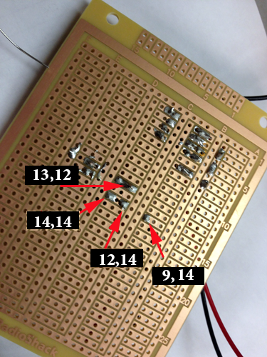
Solder the longer lead of the 220µF to pin (12,12) and the shorter to (13,14), then connect the red wire of the rheostat to (12,14) and the black wire to (9,14)
Here is the back:
Connect a wire at (14,4) to (16,4)
Here is the back:
Connect power to GND with the 100µF capacitor. If the power supply has any abrupt voltage or current spikes, this capacitor works to smooth out the signal so that it evens out those spikes:
Here is the back:
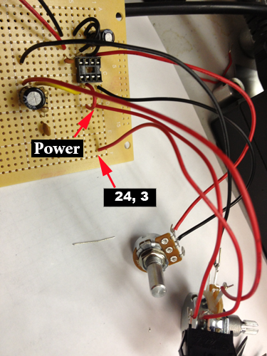
Connect one wire from the switch to the power rail (16,3) and the other wire to (24,3):
Connect the black wire of the Battery Clip to (21,3) and the red wire to (23,3):
Here is the back:
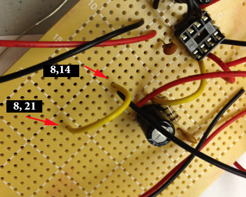
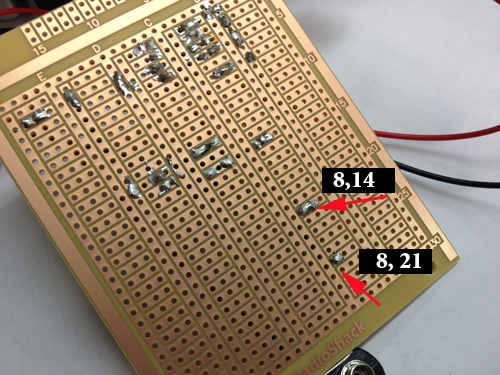
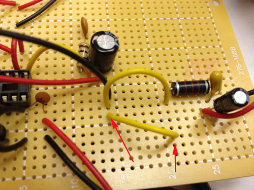
Now you are going to add the filters. Connect a wire from (8,14) to (8,21):
Here is the back:
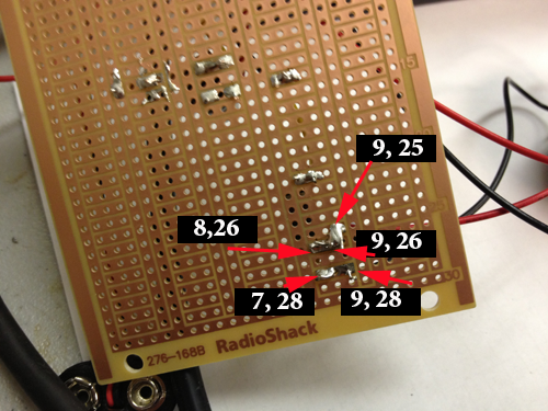
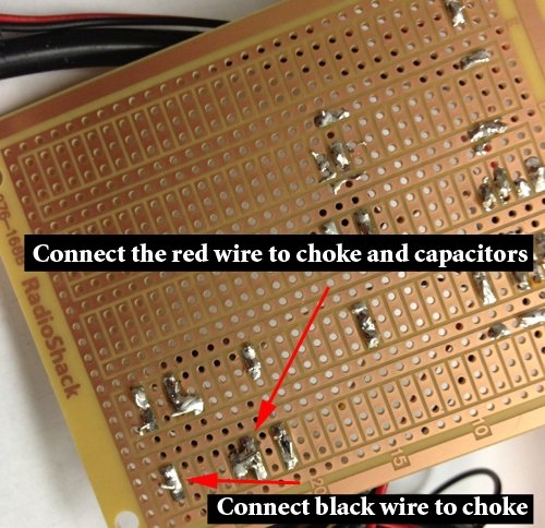
Connect (9,21) and (9,25) with a choke:
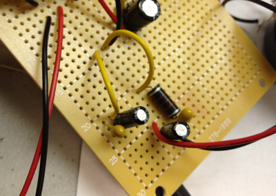
Add the long leads from the 2.2µF and the 22µF capacitors to (8,26) and (7,26) and the short leads to (9,28) and (7,28):
Here is the back:
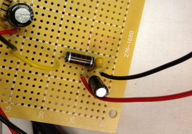
Connect the long leads of the capacitors to the choke:
Add the red wire of the bass speaker to the long leads of the capacitors and the black wire of the speaker to the short leads
Connect (7,14) to (4,21) with a wire:
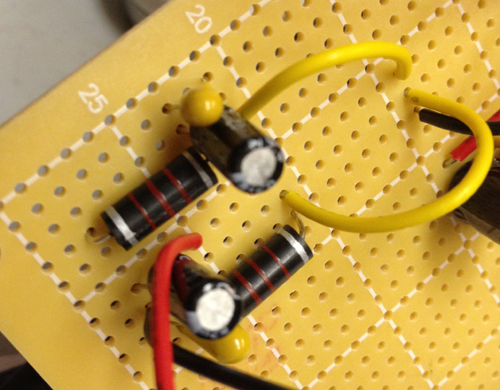
Add the long leads of the second pair of the 2.2µF and the 22µF capacitors to (2,21) and (3,21) and the short leads to (2,23) and (3,23):
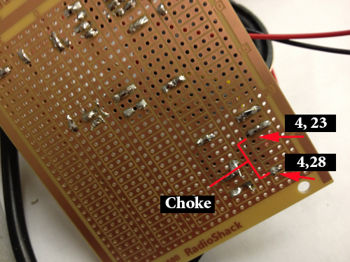
Add the second choke to connect (4, 23) and (4,28): Here is the back:
Add the red wire of the treble speaker to (3,24) and the black wire of the speaker to (3,28): Here is the back:
Add a wire to connect(2,28) and (5,28). You are connecting the black wire of the speaker to GND. Here is the back:
Add a wire to connect (8,29) and (10,30). You are connecting the black wire of the speaker to GND. Here is the back:
Use a digital caliper to measure your components. Write down the dimensions.
Think about how people use amplifiers. Follow the steps of the design process, then design the housing that reflects your thought process.
Basic steps of the Design Process
The Design Process requires
Describe the general situation or problem you are trying to solve. Instead of asking what do you want to design? ask why do you want to design that? and what problem and or need will your design ultimately be solving? In this case you need to decide how this amplifier is going to be used and that answer will inform your design decisions.
Identify your target audience, the group that will benefit from your project. Is the target population an individual, a group, a specific community, or a larger, identifiable population? Is the target population from a specific location (country, region, town), demographic (age or gender), or other identifying characteristics (health condition or employment)? Think about how is your target population connected?
Identify the requirements and constraints. A requirement is a need or a necessity; it's what a particular product or service should do. A constraint is a restriction on the degree of freedom you have in providing a solution to a need or problem.
Ask what are the disadvantages of the present solution to the problem?
Ask what compromises have been made in the present solution?
Determine if the compromises are necessary?
Determine if the solution can be improved?
By taking a new approach.
By making the design more accurate
By making the design more safe
By making the design more convenient
By making the design easier to maintain
By making the design cheaper to produce.
By making the design more attractive
Determine if you can reduce the costs by eliminating parts, using different materials, changing the way the product is manufactured?
In a nutshell
Design Step 1: Identify the Need
Design Step 2: Research the Problem
Design Step 3: Brainstorm Possible Solutions
Design Step 4: Engineering Analysis-select the most promising solution
Design Step 5: Construct a Prototype
Design Step 6: Evaluate/Manufacture a Final Product-Reiterate
Getting Started
Keep a notebook to keep track of your questions and answers. The design process will help inform your choices and should be an integral part of your creative process.
Research existing solutions. What aspects of the design appeal to you, why?
Research the history of your object. Make sure you know more about mini amps than what is provided here on this web page.
What are your constraints? Make a list.
Observe how people use mini amps, visit sites like radioshack and see how their customers use their mini amp.