Introduction
The Spark Core is a Wi-Fi development kit for internet-connected hardware.
The Core has a microcontroller, which runs a single application (often called firmware or an embedded application). Microcontrollers have a set of pins that are called GPIO (General Purpose Input and Output) pins, or I/O pins. They can be hooked to sensors or buttons to listen to the world, or they can be hooked to lights and motors to act upon the world. The pins labeled D0 to D7 and A0 to A7 are hooked directly to the microcontroller's GPIO pins.
The microcontroller can also communicate with other chips using common protocols like
Serial (also called UART),
SPI, or
I2C (also called Wire). You can also connect the Core to special-purpose chips like motor drivers or shift registers. The Core also has a Wi-Fi module, which connects it to your local Wi-Fi network in the same way that your computer or smartphone might connect to a Wi-Fi network. The Core is programmed to stay connected to the internet by default, as long as it can find and connect to a network.
When the Core connects to the internet, it establishes a connection to the Spark Cloud. By connecting to the Cloud, the Core becomes accessible from anywhere through a simple
REST API. This API is designed to make it very easy to interface with the Core through a web app or mobile app in a secure, private way, so that only you and those you trust can access the Core.
Serial (UART)
The Core features two serial ports. The first one is a CDC (Communications Device Class) available over the USB port. When configured, it will show up as a virtual COM port on the computer. The second one is a hardware USART available via the TX and RX pins on the Core. Both of these serial ports can be configured and used using the serial functions.
NOTE: Please take into account that the voltage levels on these pins runs at 0V to 3.3V and should not be connected directly to a computer's RS232 serial port which operates at +/- 12V and can damage the Core.
SPI
The Serial Peripheral Interface is available on pins:
- A2: SS (Slave Select)
-
A3: SCK (Serial Clock)
-
A4: MISO (Master In Slave Out)
-
A5: MOSI (Master Out Slave In)
I2C
I2C communication pins are multiplexed with the standard GPIO pins D0 and D1.
- D0: SDA (Serial Data Line)
-
D1: SCL (Serial Clock)
Both of these pins run at 3.3V logic level but are tolerant to 5V inputs.
What's on the Board
The Buttons
- The RESET button (on the right)
- The MODE button (on the left).
The RESET button will put the Core in a hard reset, effectively depowering and repowering the microcontroller. This is a good way to restart the application that you've downloaded onto the Core.
The MODE button serves three functions:
- Hold down the MODE button for three seconds to put the Core into Smart Config mode to connect it to your local Wi-Fi network. The LED should start flashing blue.
- Hold down the MODE button for ten seconds to clear the Core's memory of Wi-Fi networks.
-
Hold down the MODE button, tap on the RESET button and wait for three seconds to enter Bootloader mode, where you can reprogram the Core over USB or JTAG. Release the MODE button when you see the LED flashing yellow. If you do this by accident, simply hit RESET button to leave Bootloader mode.
- Hold down the MODE button, tap on the RESET button and wait for ten seconds to do a Factory Reset, where the Core is reprogrammed with the software that was installed on the Core in the factory (the Tinker application). The LED should turn white for three seconds and begin flashing quickly; when the LED switches to another color the Core has been reset. This is useful if you encounter bugs with your firmware, or if you just want to get back to Tinker.
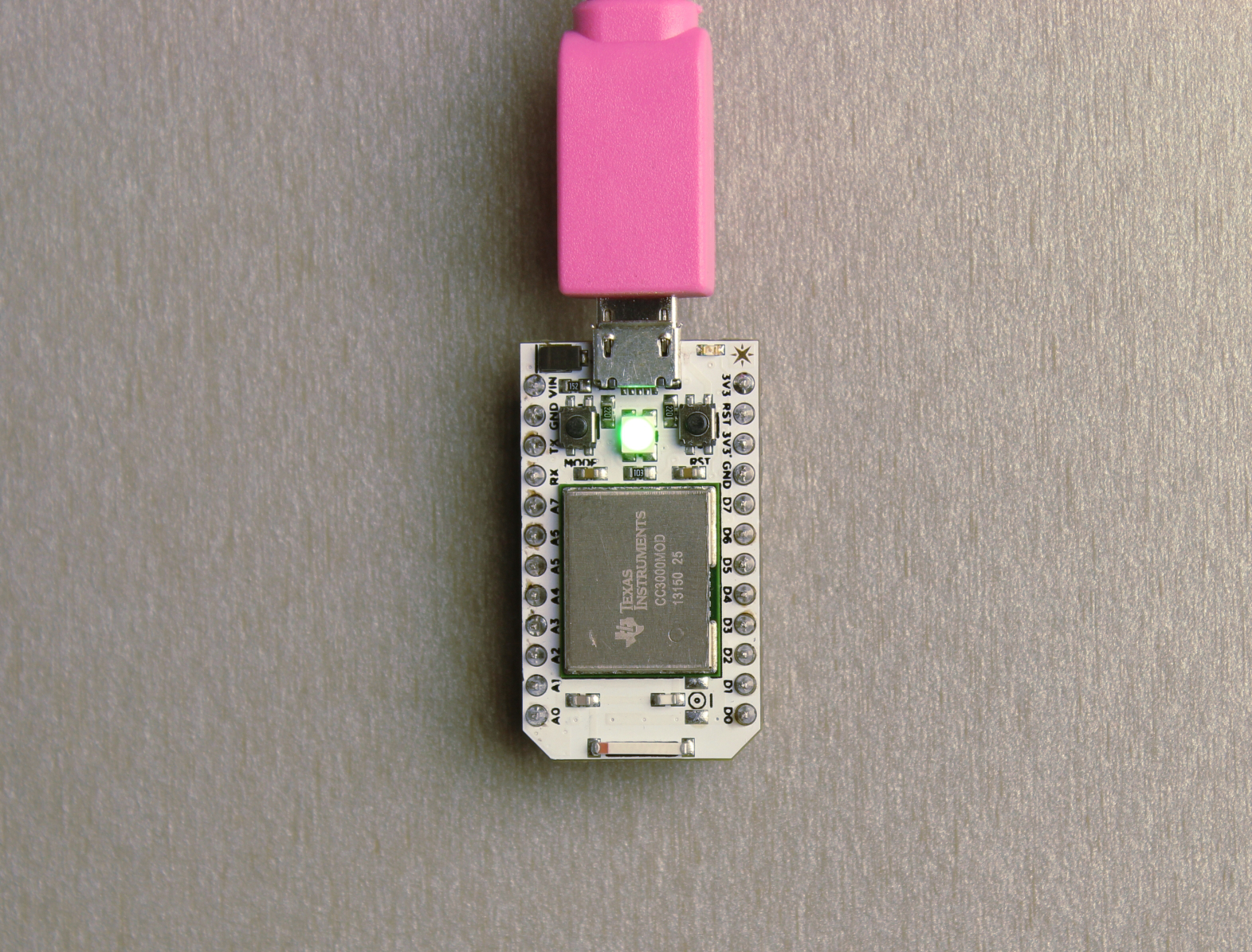
The LEDs
There are two LEDs on the Core. The one in the middle is a full-color RGB LED that shows you the status of the Core's internet connection. The other small
blue LED is the user LED; it's hooked up to D7, so when you turn the D7 pin HIGH or LOW, it turns on and off, respectively.
The RGB LED could show the following states:
- Flashing blue: Listening mode, waiting for network information.
- Solid blue: Smart Config complete, network information found.
- Flashing green: Connecting to local Wi-Fi network.
-
Flashing cyan: Connecting to Spark Cloud.
-
Slow breathing cyan: Successfully connected to Spark Cloud.
-
Flashing yellow: Bootloader mode, waiting for new code via USB or JTAG.
-
Flashing white: Factory Reset initiated.
-
Solid white: Factory Reset complete; rebooting.
The RGB LED can also let you know if there were errors in establishing an internet connection. A
red LED means an error has occurred. These errors might include:
- Two red flashes: Connection failure due to bad internet connection. Check your network connection.
-
Three red flashes: The Cloud is inaccessible, but the internet connection is fine. Check our Twitter feed to see if there have been any reported outages; if not, visit our support page for help.
-
Four red flashes: The Cloud was reached but the secure handshake failed. Visit our support page for help.
-
Flashing yellow/red: Bad credentials for the Spark Cloud. Contact the Spark team (hello@spark.io).
Pins
The Core has 24 pins that you can connect a circuit to. These pins are:
-
VIN: Connect an unregulated power source here with a voltage between 3.6V and 6V. If you're powering the Core over USB, DO NOT USE THIS pin.
-
3V3: This pin outputs a regulated 3.3V power rail that can be used to power components. (Also, if you have your own 3.3V regulated power source, you can plug it in here to power the Core).
-
3V3*: This is a separate low-noise regulated 3.3V power rail designed for analog circuitry that may be susceptible to noise from the digital components. If you're using any sensitive analog sensors, power them from 3V3* instead of from 3V3.
-
!RST: You can reset the Core (same as pressing the RESET button) by connecting this pin to GND.
-
GND: ground pins.
-
D0 to D7: 8 GPIO (General Purpose Input/Output) pins. They're labeled D because they are Digital pins, meaning they can't read the values of analog sensors. Some of these pins have additional peripherals (SPI, JTAG, etc.) available.
-
A0 to A7: These pins are just like D0 to D7, but they are Analog pins, which means they can read the values of analog sensors (technically speaking they have an ADC peripheral). As with the Digital pins, some of these pins have additional peripherals available.
-
TX and RX: These pins are for communicating over Serial/UART. TX represents the transmitting pin, and RX represents the receiving pin.
- PWM pins:When you want to use the analogWrite() function, you need to use pins that have a timer peripheral. People often call these PWM pins, since what they do is called Pulse Width Modulation. The Core has 8 PWM pins: A0, A1, A4, A5, A6, A7, D0 and D1.
THE SPARK CLOUD
Generally speaking, when you work in an embedded system, networking happens when you send bytes over TCP sockets and UDP datagrams.
Higher-level communications are generally difficult because microcontrollers have little memory and they can't generally host a traditional HTTP web server. The Spark Cloud gives you the simplicity of the web server with the low cost and low power of a microcontroller by translating between web communications (HTTP requests) and embedded communications (in our case, encrypted CoAP messages).
The best part of the Cloud is that the difficult part of communication is abstracted, so you don't need to know how it connects to the internet. And once it's connected, you can make it do things quickly and easily, without dealing with sockets.
By default, if you connect a thing to your Wi-Fi network, it's only available from elsewhere on your local network. This is a result of the fact that we've run out of IP addresses, and it's also a security measure, since it means that people can't just reach into your home and mess with your stuff.
Making the stuff in your home available outside your home is generally a pain, and usually requires things like
port mapping and
static IP addresses. The Cloud lets you ignore this part. The Core connects to the Cloud when it hits your Wi-Fi network, and holds open a persistent connection. This means that it's available from anywhere in the world at any time.
Security is hard. It's especially hard on an embedded system, because encryption is resource intensive. But it's also important, because you don't want just anyone turning on and off your lights.The Spark Core hand-picked a set of rock-solid security protocols that are secure and efficient, and work great on an embedded system. They're baked into the Spark Protocol, which is open source and ready to be extended to other products.
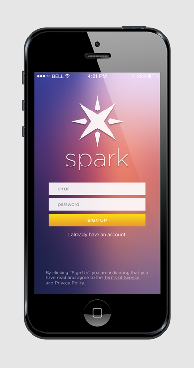
Using your smartphone
- Download the smartphone app:
- Create an account with Spark
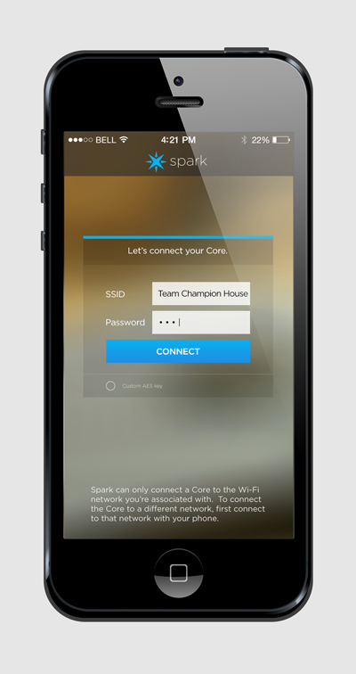
- Connect your Spark Core to your Wi-Fi network by connecting the core to your computer over USB
- Control your Core without writing any code by opening up Tinker on your phone:
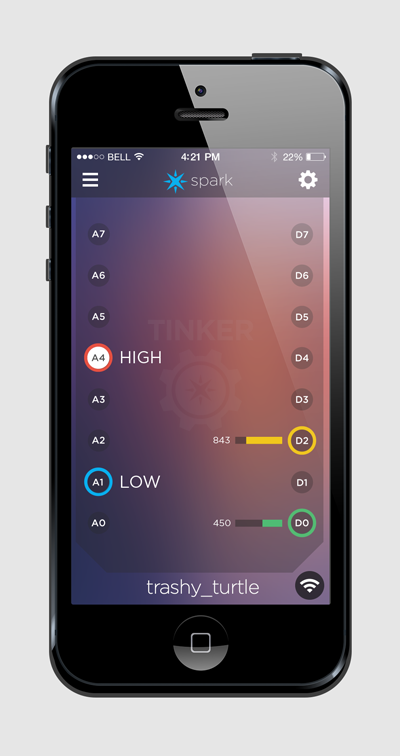
- The app consists of 16 pins in vertical rows - 8 analog pins on the left, 8 digital pins on the right. These pins represent the 16 GPIO (General Purpose Input and Output) pins on the Spark Core, and are organized the same way.
To begin, tap any of the pins. A menu will pop up showing the functions that pin has available. Each pin can have up to four possible functions:
-
digitalWrite: Sets the pin to HIGH or LOW, which either connects it to 3.3V (the maximum voltage of the system) or to GND (ground). Pin D7 is connected to an on-board LED; if you set pin D7 to HIGH, the LED will turn on, and if you set it to LOW, it will turn off.
- analogWrite: Sets the pin to a value between 0 and 255, where 0 is the same as LOW and 255 is the same as HIGH. This is sort of like sending a voltage between 0 and 3.3V, but since this is a digital system, it uses a mechanism called Pulse Width Modulation, or PWM. You could use analogWrite to dim an LED, as an example.
- digitalRead: This will read the digital value of a pin, which can be read as either HIGH or LOW. If you were to connect the pin to 3.3V, it would read HIGH; if you connect it to GND, it would read LOW. Anywhere in between, it’ll probably read whichever one it’s closer to, but it gets dicey in the middle.
- analogRead: This will read the analog value of a pin, which is a value from 0 to 4095, where 0 is LOW (GND) and 4095 is HIGH (3.3V). All of the analog pins (A0 to A7) can handle this. analogRead is great for reading data from sensors.
To change the function of the pin, simply tap and hold on the pin, and the function select menu will come back up.
- You can always get back to it by putting the Core in the factory reset mode
Hold down the MODE button, tap on the RESET button and wait for ten seconds to do a Factory Reset, where the Core is reprogrammed with the software that was installed on the Core in the factory (the Tinker application). The LED should turn white for three seconds and begin flashing quickly; when the LED switches to another color the Core has been reset.
Tinker API
The Tinker API requests can also be made from an application other than Tinker, so you can build your own web or mobile app around the Tinker firmware.
digitalWrite
Sets the pin to HIGH or LOW, which either connects it to 3.3V (the maximum voltage of the system) or to GND (ground). Pin D7 is connected to an on-board LED; if you set pin D7 to HIGH, the LED will turn on, and if you set it to LOW, it will turn off.
POST /v1/devices/{DEVICE_ID}/digitalwrite

# EXAMPLE REQUEST IN TERMINAL
# Core ID is 0123456789abcdef01234567
# Your access token is 1234123412341234123412341234123412341234
curl https://api.spark.io/v1/devices/0123456789abcdef01234567/digitalwrite \
  -d access_token=1234123412341234123412341234123412341234 -d params=D0,HIGH
The parameters must be the pin (A0 to A7, D0 to D7), followed by either HIGH or LOW, separated by a comma. The return value will be 1 if the write succeeds, and -1 if it fails.
analogWrite
Sets the pin to a value between 0 and 255, where 0 is the same as LOW and 255 is the same as HIGH. This is sort of like sending a voltage between 0 and 3.3V, but since this is a digital system, it uses a mechanism called Pulse Width Modulation, or PWM. You could use analogWrite to dim an LED, as an example.
POST /v1/devices/{DEVICE_ID}/analogwrite

# EXAMPLE REQUEST IN TERMINAL
# Core ID is 0123456789abcdef01234567
# Your access token is 1234123412341234123412341234123412341234
curl https://api.spark.io/v1/devices/0123456789abcdef01234567/analogwrite \
  -d access_token=1234123412341234123412341234123412341234 -d params=A0,215
The parameters must be the pin (A0 to A7, D0 to D7), followed by an integer value from 0 to 255, separated by a comma. The return value will be 1 if the write succeeds, and -1 if it fails.
digitalRead
This will read the digital value of a pin, which can be read as either HIGH or LOW. If you were to connect the pin to 3.3V, it would read HIGH; if you connect it to GND, it would read LOW. Anywhere in between, it’ll probably read whichever one it’s closer to, but it gets dicey in the middle.
POST /v1/devices/{DEVICE_ID}/digitalread

# EXAMPLE REQUEST IN TERMINAL
# Core ID is 0123456789abcdef01234567
# Your access token is 1234123412341234123412341234123412341234
curl https://api.spark.io/v1/devices/0123456789abcdef01234567/digitalread \
  -d access_token=1234123412341234123412341234123412341234 -d params=D0
The parameter must be the pin (A0 to A7, D0 to D7). The return value will be 1 if the pin is HIGH, 0 if the pin is LOW, and -1 if the read fails.
analogRead
This will read the analog value of a pin, which is a value from 0 to 4095, where 0 is LOW (GND) and 4095 is HIGH (3.3V). All of the analog pins (A0 to A7) can handle this. analogRead is great for reading data from sensors.
POST /v1/devices/{DEVICE_ID}/analogread

# EXAMPLE REQUEST IN TERMINAL
# Core ID is 0123456789abcdef01234567
# Your access token is 1234123412341234123412341234123412341234
curl https://api.spark.io/v1/devices/0123456789abcdef01234567/analogread \
  -d access_token=1234123412341234123412341234123412341234 -d params=A0
The parameters must be the pin (A0 to A7, D0 to D7). The return value will be between 0 and 4095 if the read succeeds, and -1 if it fails.
WEB IDE
Spark Build is an Integrated Development Environment, or IDE; that means that you can do software development in an easy-to-use application that run in your web browser.
- The Web IDE can be found here.
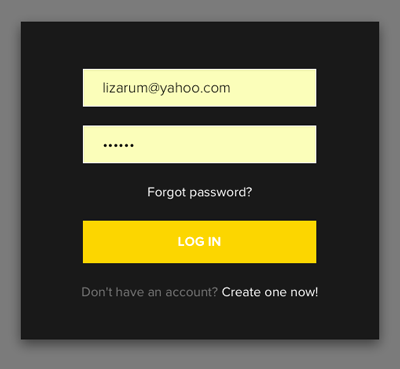
- Login
- This is the screen for a new application:
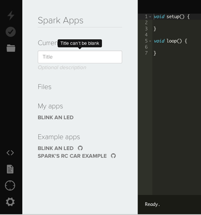
On the top, there are three buttons:
- Flash: Flashes the current code to the Spark Core. This initiates an over-the-air firmware update and loads the new software onto your Spark Core.
-
Verify: This compiles your code without actually flashing it to the Core; if there are any errors in your code, they will be shown in the debug console on the bottom of the screen.
-
Save: Saves any changes you’ve made to your code.
At the bottom, there are four buttons to navigate through the IDE:
- Code: Shows a list of your firmware applications and lets you select which one to edit/flash.
-
Docs: Brings you to the documentation for Spark.
- Cores: Shows a list of your Spark Cores, so you can choose which to flash, and get more information on each Core.
-
Settings: Change your password, log out, or get your access token for API calls.
- Try it out:
int LED = D7;

void setup() {
    pinMode(LED, OUTPUT);
}

void loop() {
    digitalWrite(LED, HIGH);
    delay(250);
    digitalWrite(LED, LOW);
    delay(250);
}
- You can create programs with multiple files. This works just like in Arduino IDE where the main application is an "Arduino" file, and additional files/libraries are normal C++ source files and header files (which are not run through the pre-processor).
There are a few things to be aware of:
-
If you create additional files, the UI automatically creates both a header file (.h) and a source file (.cpp), and a #include statement for the header file. However you are free to delete or modify the line of code that we automatically insert.
Claiming Your Core
Once your Core is connected, it needs to be claimed in order to be associated with your account. This is what lets you control your Core and keeps anyone else from doing so.
If you use the mobile app to set up your Core, it should claim it automatically. However if you connect your Core over USB, or if the claiming process is unsuccessful, you can claim it manually.
- Open Cool Term
- Connect to the Core
- Type the letter i to get the id
You should see something like:
# Example Core ID
55ff68064989495329092587
- Open up Spark Build
-
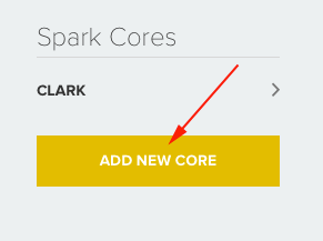
Click the ‘Cores’ icon.

- Click the button that says ‘Add a Core’
- Enter your ID in the text box.
Spark Core API
Every Spark Core has a URL, which can be used to GET variables, POST a function call, or PUT new firmware. The variables and functions that you have written in your firmware are exposed as subresources within the Spark Core.
- List devices the currently authenticated user has access to.
- Get basic information about the given Core, including the custom variables and functions it has exposed.
GET /v1/devices/{DEVICE_ID}
- Update the Core, including the display name or the firmware (either binary or source).
PUT /v1/devices/{DEVICE_ID}
- Request the current value of a variable exposed by the core
GET /v1/devices/{DEVICE_ID}/{VARIABLE}
- Call a function exposed by the core, with arguments passed in request body
POST /v1/devices/{DEVICE_ID}/{FUNCTION}
- // SYNTAX TO REGISTER A SPARK FUNCTION
Spark.function("funcKey", funcName);
- Spark.sleep() can be used to dramatically improve the battery life of a Spark-powered project by temporarily deactivating the Wi-Fi module, which is by far the biggest power draw.
Spark.sleep() can also be used to put the entire Core into a deep sleep mode.
The Core will automatically wake up and reestablish the WiFi connection after the specified number of seconds.
Spark.sleep(int seconds);
Spark.sleep(SLEEP_MODE_DEEP, int seconds);
Built in Libraries
Servo
This library allows a Spark Core to control RC (hobby) servo motors. Servos have integrated gears and a shaft that can be precisely controlled. Standard servos allow the shaft to be positioned at various angles, usually between 0 and 180 degrees. Continuous rotation servos allow the rotation of the shaft to be set to various speeds.
// EXAMPLE CODE

Servo myservo;  // create servo object to control a servo
                // a maximum of eight servo objects can be created

int pos = 0;    // variable to store the servo position

void setup() {
  myservo.attach(A0);  // attaches the servo on the A0 pin to the servo object
}


void loop() {
  for(pos = 0; pos < 180; pos += 1)  // goes from 0 degrees to 180 degrees
  {                                  // in steps of 1 degree
    myservo.write(pos);              // tell servo to go to position in variable 'pos'
    delay(15);                       // waits 15ms for the servo to reach the position
  }
  for(pos = 180; pos>=1; pos-=1)     // goes from 180 degrees to 0 degrees
  {
    myservo.write(pos);              // tell servo to go to position in variable 'pos'
    delay(15);                       // waits 15ms for the servo to reach the position
  }
}
RGB
This library allows the user to control the RGB LED on the front of the Spark Core.
// EXAMPLE CODE

// take control of the LED
RGB.control(true);

// red, green, blue, 0-255
RGB.color(0, 0, 0);

// wait one second
delay(1000);

// resume normal operation
RGB.control(false);
Check out some annotated
examples
Serial
To see Serial you can either install the Spark -CLI and type the following into your terminal:
or connect to your core using a serial program like CoolTerm.
Adding WiFi Networks
You can bring your core to different locations, but you'll need to add the different WiFi networks to the credentials.
On a Mac, use CoolTerm.
- Make sure the core is in USB mode, Press the left nutton until the core flashes blue.
- Choose the Port and turn on local echo in CoolTerm
- Connect
- Type i to get your Core ID
- Type w to set up your network
- Follow the prompts and disregard the extra letters that appear
- Wait 7 seconds and your core should reset
On Windows use Putty or follow the directions found
here
Spark-CLI
Spark Command Line Interface for the Cloud
-
Download and install node.js
- Next in the terminal:
I had to use sudo
- Type spark to see the list of available commands
spark cloud        - simple interface for common cloud functions
spark flash        - copies firmware and data to your core over usb
spark function     - call functions on your core
spark help         - Help provides information on available commands in the cli
spark keys         - tools to help you manage keys on your cores
spark serial       - simple serial interface to your cores
spark setup        - Helps guide you through the initial claiming of your core
spark subscribe    - helpers for watching Core event streams
spark udp          - helps repair cores, run patches, check wifi, and more!
spark variable     - retrieve and monitor variables on your core
- The first thing you should do is login to your account:
- Will return a list of your cores.
-
spark variable get all name_of_var
- Will help you connect your core to your wifi network
