TinkerCad
Introduction
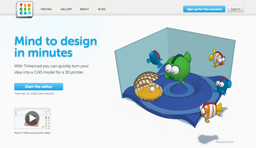
Tinkercad is an easy-to-use tool for creating 3D models for 3D printing. It is part of the Autodesk family of products, which are not only free, but exist to enable students, makers, and individuals from all walks of life to design and make the things they imagine.
- Navigate in a web-gl enabled browser (Chrome or Firefox) to tinkercad.com
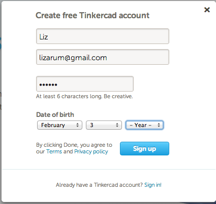
- If you have not already signed up for a free account, do so now

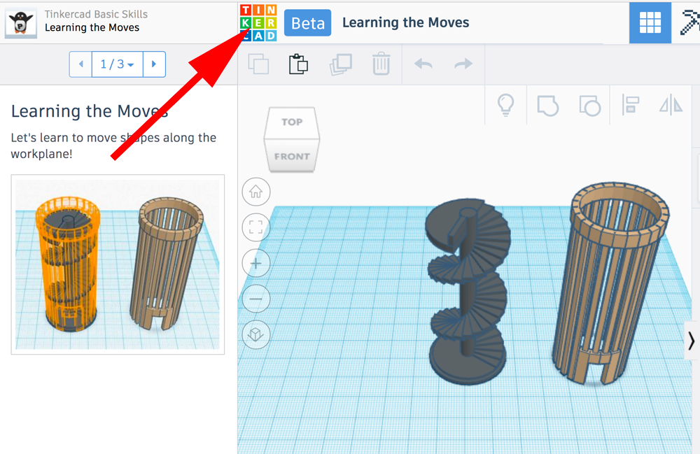
- To exit the tutorial and start experimenting, exploring and modeling click on the Tinkercad logo:
- To start a new model click on Create new design

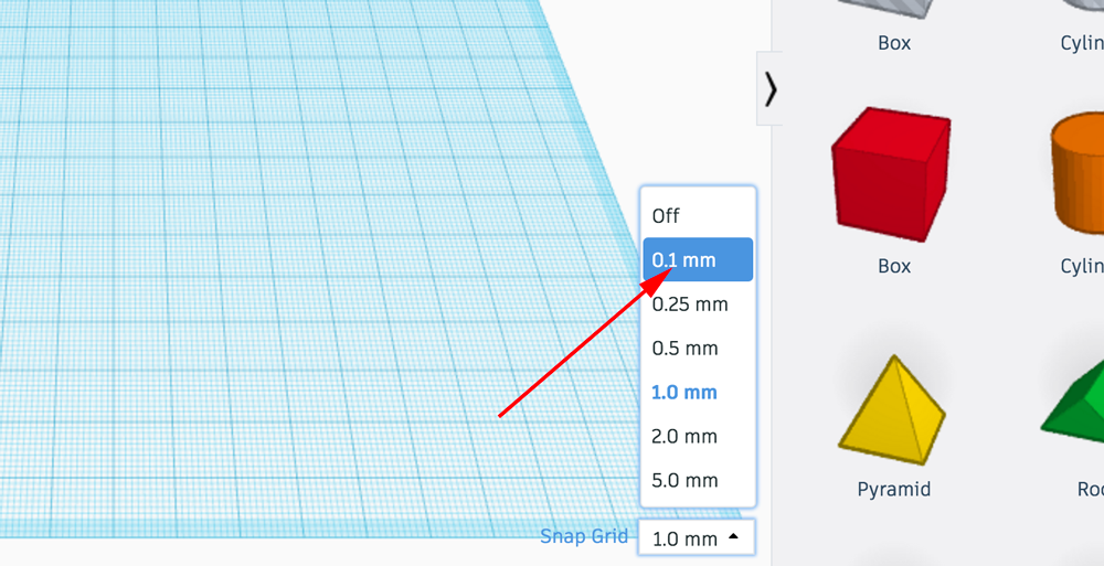
- For greater precision I toggle the Snap grid value between 0.1 and 1.0
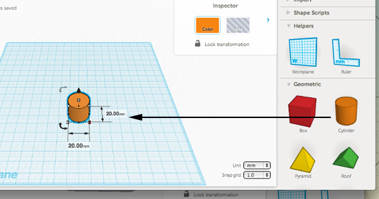
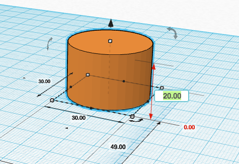
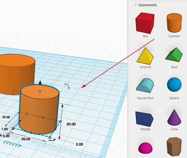
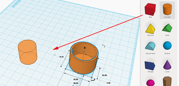
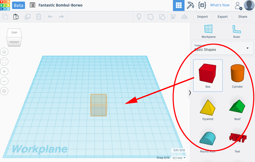
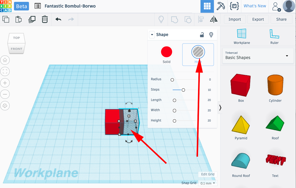
- To add shapes, letters and numbers you drag your selection from the palette on the right over to the workplane:
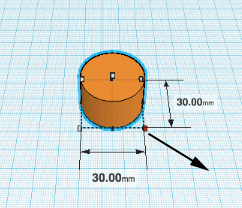
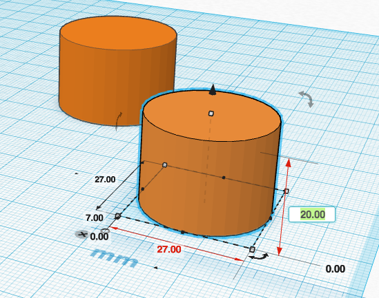
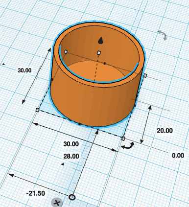
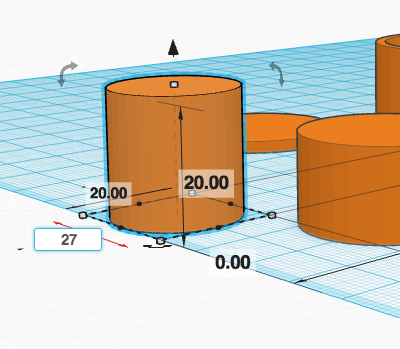
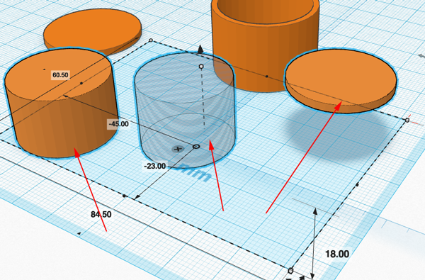
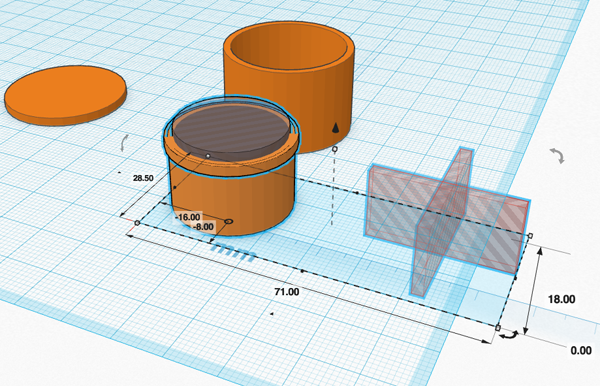
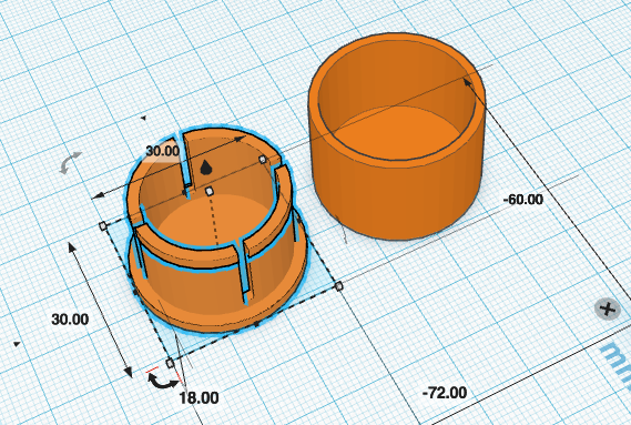
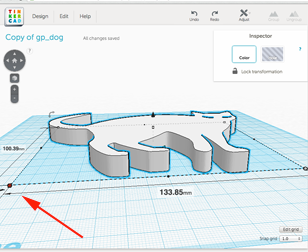
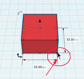
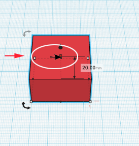
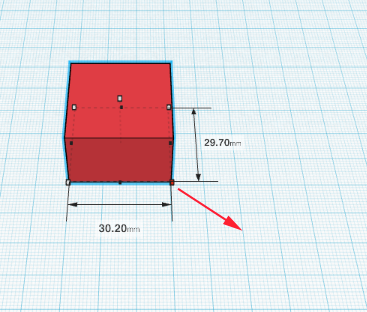
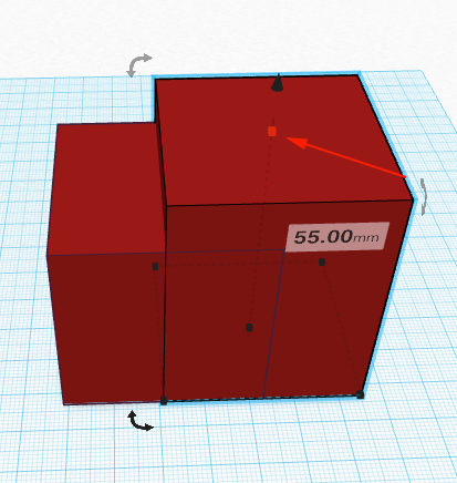
- You can get the dimensions of an object by moving the cursor over the nodes or handles:
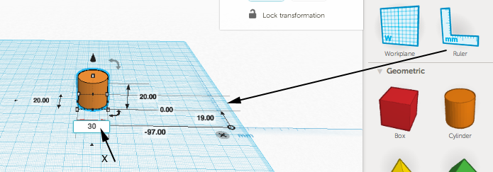
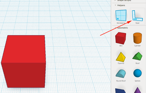
- You can also get and/or modify the dimensions by laying down the ruler:
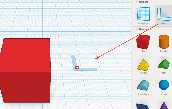
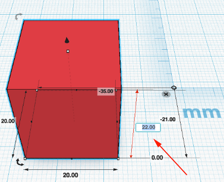
- Drag the ruler to the corner of an object and click on the circle to select a quadrant to measure. This is helpful when you want to measure distances between objects:
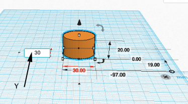
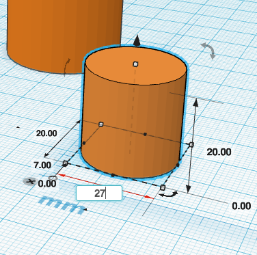
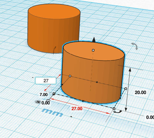
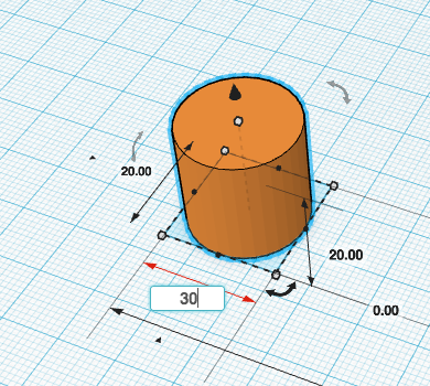
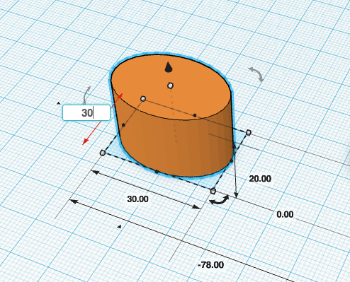
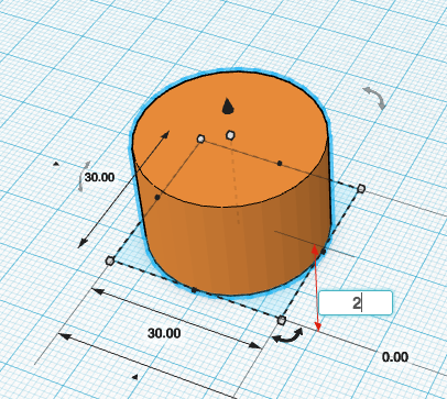
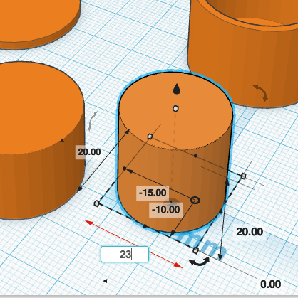
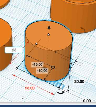
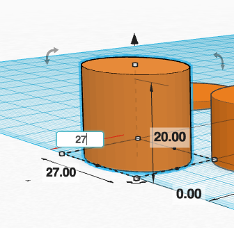
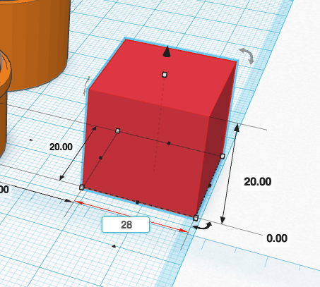
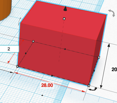
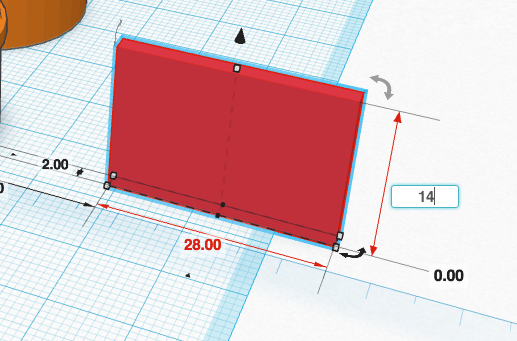
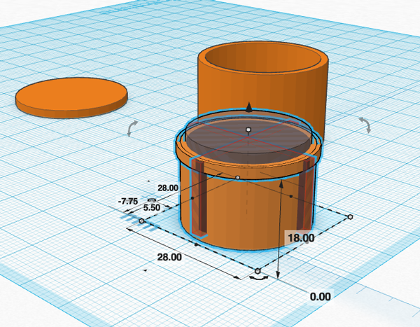
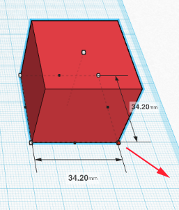
- You can resize your form by dragging the corner points (nodes) or using the ruler and editing the field:
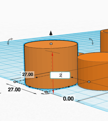
- Dragging the corner node while holding shift will increase the X,Y and Z axis proportionally:
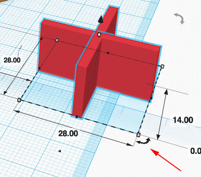
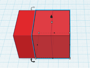
- You can copy and paste your forms using the standard keyboard commands. When you paste, Tinkercad will move your new form to the right:
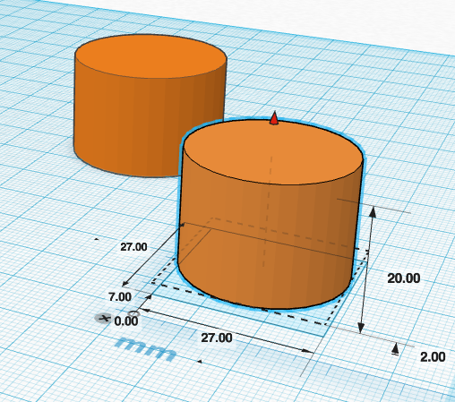
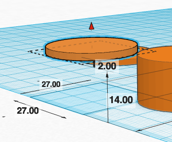
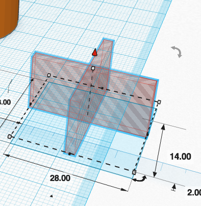
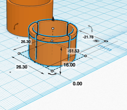
- You can raise the height of your form by dragging the node below the cone
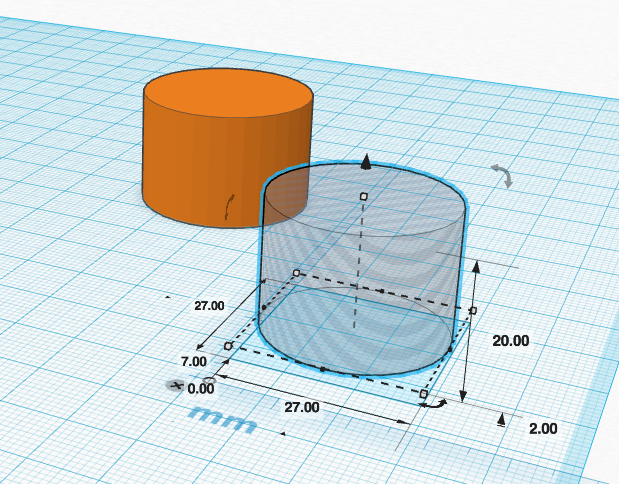
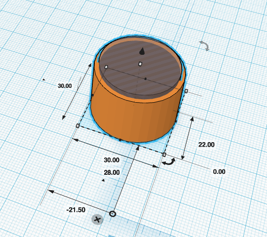
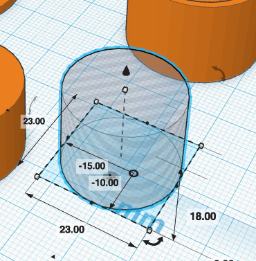
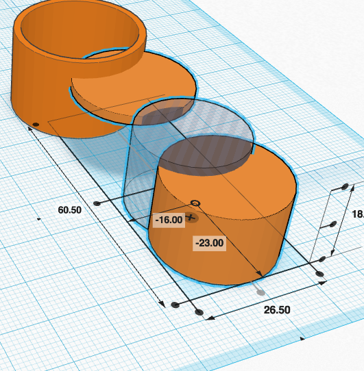
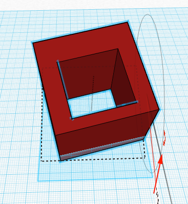
- You can subtract shapes from each other by placing the shape you want to remove, selecting it and then clicking on the the hole icon
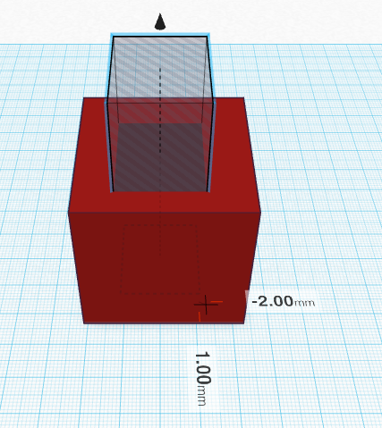
- You can still adjust the location of the hole by dragging the form
-
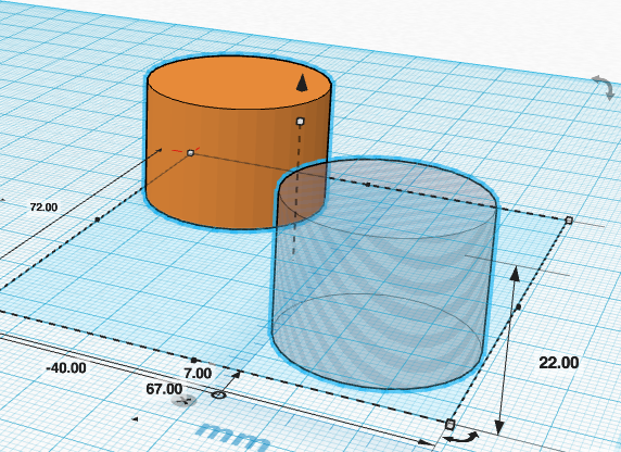
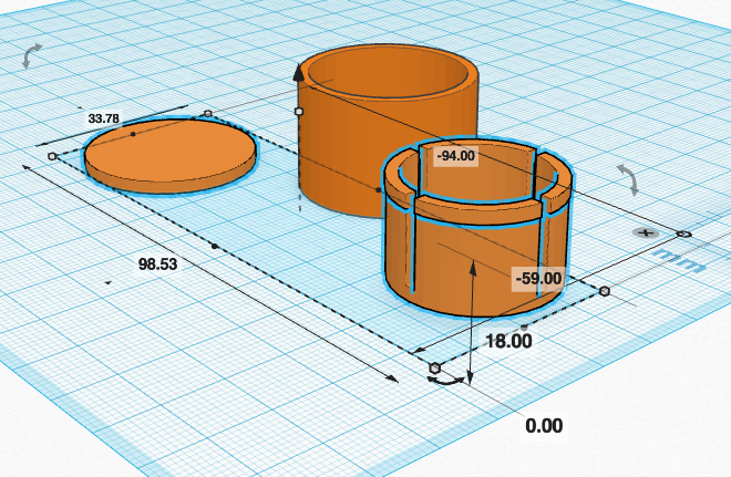
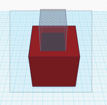
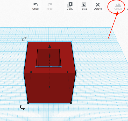
When you want to remove the shape, drag your cursor over or Shift+Left Click on both objects (what you want to keep and what you want to remove)
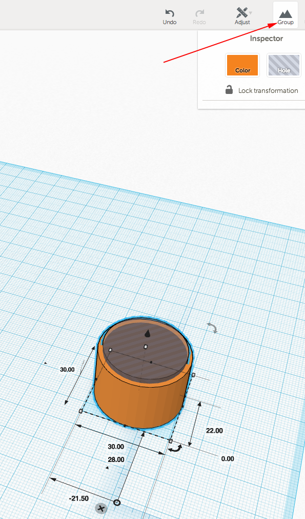
- When both are selected, click on Group
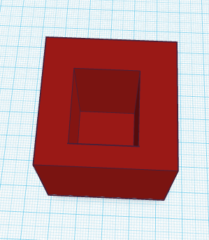
- To view the hole, rotate with the mouse:
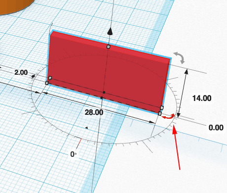
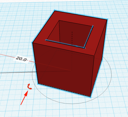
- Tinkercad's rotate tool allows you to change the angle of your model or part of your model along the x, y or z axis.
Tinkercad allows you to choose your resolution by providing three rings. Once you start the rotation you can move your mouse over the appropriate band. The center band allow you to adjust the rotation by full degrees. The inner band adjusts the angle in increments of 22.5° (half of 45°) and the outer band allows you the most precision.
You can easily rotate your objects by clicking on the rotation icons and then selecting the band:

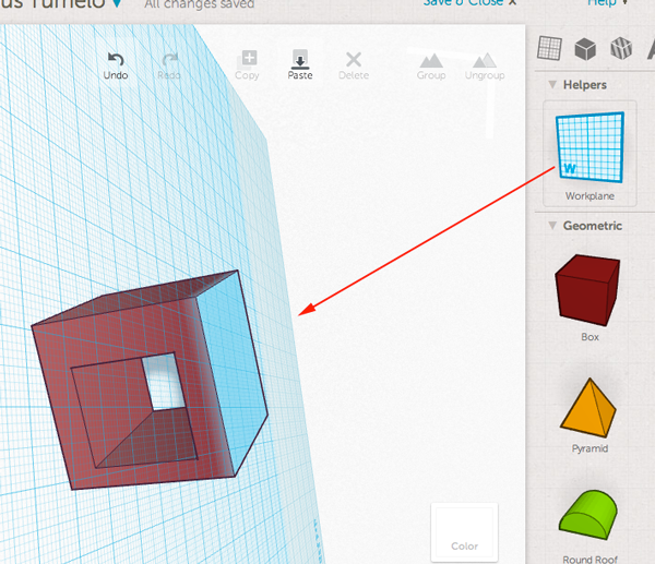
- You can move the workplane by placing it on a side of any of your forms. This allows you to add more forms on an angle:
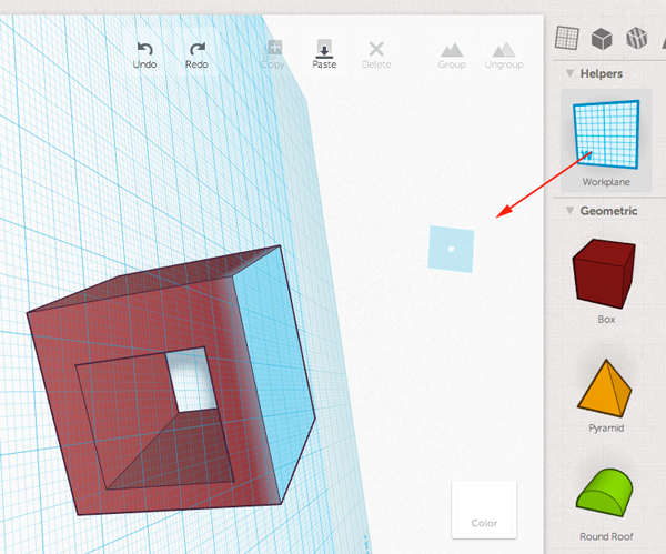
- To reset the workplane, just drag the workplane from the palette to the work area:
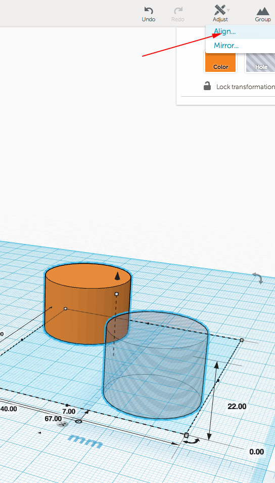
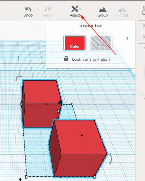
- Tinkercad's Align tool allows you to align multiple objects.
To use the Align tool. Select at least two objects by Shift left-clicking on them or by dragging a box around them. Once selected click on the Adjust Option at the top. Then select Align and move your mouse over a node to preview the move. Click the node to align the objects.
- Select objects and click Adjust:
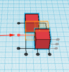
- Now select Align
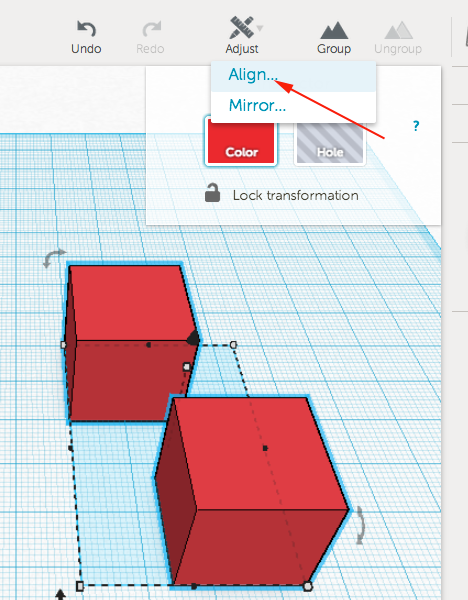
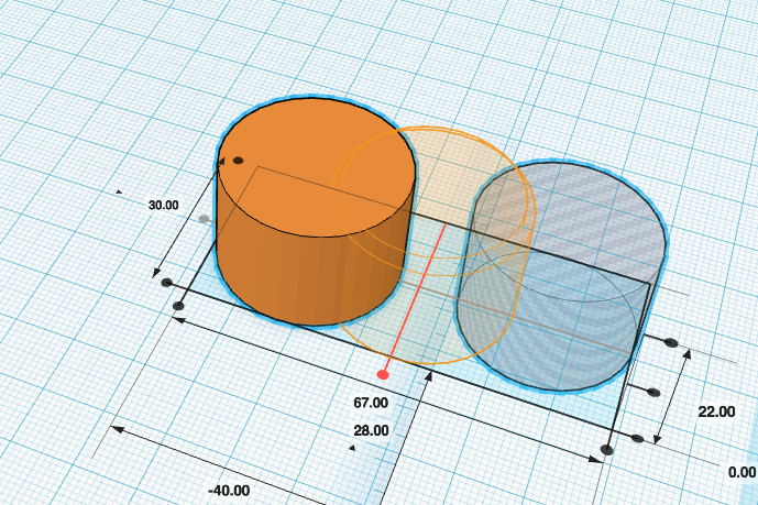
- Click on the node you would like the forms to align with:
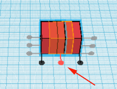
-
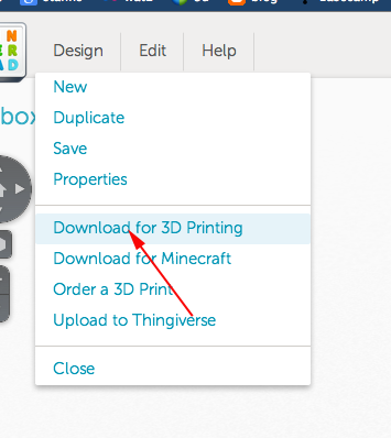
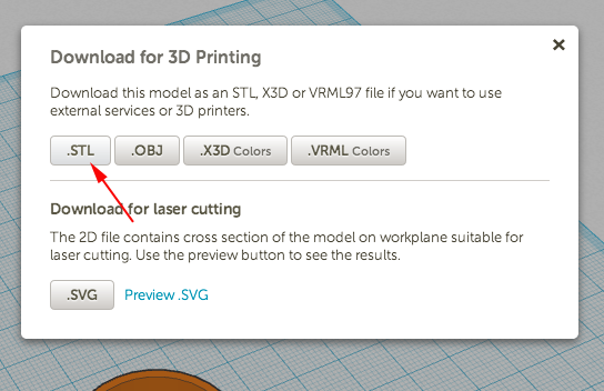
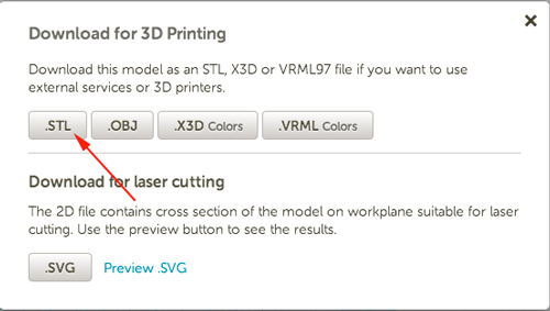
- To save the STL file, click on Design and select Download for 3D Printing:
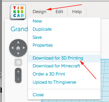
Then select on the STL button:
- Experiment, have fun, print
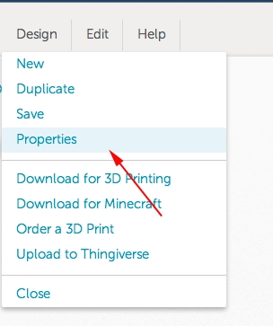
- When you are ready to print your object, click on the Design menu and select Properties.
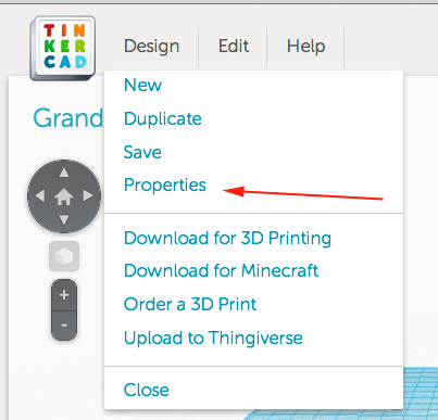
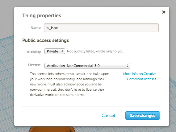
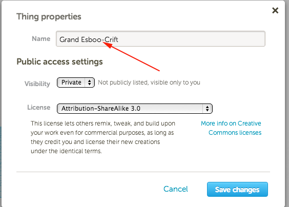
- Rename your file and save the changes
- From the Design menu select Download for 3D Printing:
- Select on the STL button:
A few Tinkercad skill builder challenges
To get
Tinkercad to run on Mac with Firefox you'll have to do the following:
- Type about:config in the Firefox 4 URL bar
- Type webgl in the search box
- webgl.force-enabled = true
- Go to https://tinkercad.com and refresh the page
Background: Driver support on older OS/Graphics card combinations is bad so the browser vendors have blacklisted a number of devices. All of Mac OS X 10.5 is blacklisted in Firefox, what you did above is circumvent this blacklisting.
Windows
on Windows XP, WebGL and acceleration is blacklisted.
To enable it,
in command line:
chrome.exe --enable-webgl
or
- Close any open Chrome windows
- Find the Chrome shortcut you use (normally on the desktop or in the start menu) and right click on it.
- Select 'Properties'
- Add the '--ignore-gpu-blacklist' flag without the quotes at the end of the 'Target' box
or
- type "about:flags" on address bar of google chrome
- under "Override software rendering list" click "enable"
- scroll down and "relaunch google chrome"
Linux
In command line:
or
google-chrome --ignore-gpu-blacklist
Mouse shortcuts:
Right Click is the same as CTRL+click.
- right drag/CTRL+drag rotate the camera
- middle mouse drag pan the camera
- mouse wheel zoom in and out
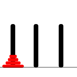
Model a Tower of Hanoi Game
In an ancient city, monks in a temple have the task of moving a pile of 64 sacred disks from one location to another. The disks are fragile; only one can be carried at a time. A disk may not be placed on top of a smaller, less valuable disk. And, there is only one other location in the temple (besides the original and destination locations) sacred enough that a pile of disks can be placed there.
The Towers of Hanoi is a game where various-sized disks are piled up on a base in order of decreasing size. The object of the game is to move the stack from one base to another, subject to two rules:
- Only one disk can be moved at a time
- No disk can ever be placed on top of a smaller disk.
There is a third base that can be used as a spare.

If there are N disks on the first stack, you know that you will eventually have to move the bottom disk from that stack to the next stack. Before you can move the largest disk from the first stack to the bottom of the second stack, the first N-1 disks must be on the temporary stack. Once you've moved the N-th disk to the final stack, you must move the other N-1 disks from the temporary stack to the final stack to complete the solution. But moving N-1 disks is the same type of problem as moving N disks, except that it's a smaller version of the problem. In the recursive subroutine that solves the problem, the stacks that serve as the source and destination of the disks have to be specified. It's also convenient to specify the stack that is to be used as a spare, even though you could figure that out from the other two parameters. The base case is when there is only one disk to be moved. The solution in this case is trivial: Just move the disk in one step. Here is a version of the subroutine that will solve the problem:
 TowersOfHanoi(int disks, int from, int to, int spare) {
   if (disks == 1) {
          // There is only one disk to be moved.  Just move it.
      //"Move a disk from stack number "+ from + " to stack number " + to);
   }
   else {
         /* Move all but one disk to the spare stack, then
            move the bottom disk, then put all the other
            disks on top of it.*/
     //TowersOfHanoi(disks-1, from, spare, to);
     //"Move a disk from stack number "+ from + " to stack number " + to);
      //TowersOfHanoi(disks-1, spare, to, from);
   }
}- Create a new Project
- Click on the Design Pulldown and select Properties and name your project.
- Model
- Model one disk and print it. Make sure it can be added and removed from the stacks. The model shrinks a little bit when printed.
- Download the stl or Upload to Thingiverse.
More Ideas
-
DesignMakeTeach's PERSONALIZE A GIMBAL
Tinkercad Gyro Maker by Mathgrrl (Laura Taalman)
learn to move, align, and group objects and use that knowledge to put together a customized gyro from pre-made pieces.
Choose one small inside hole and use the sliders in the Shape Script to change the number of sides/petals or the amount of twist in the shape. Then Align the small hole with the small blue gyro center and Group them together. For the outside, choose a large shape and customize it to your liking, then Align and Group the large shape with the large hole. Finally, select the customized outer ring together with the orange, yellow, green, and customized blue gyro rings, and Align and Group together to make the final gyro.
- Coin Trap
Pause the printer, drop the coin and resume printing
Laura Taalman's Coin Trap Tutorial
- Customize the Hinged Buterfly
Ungroup and modify or just start with the hinge
- Create your own nets with these hinges or download and print Mathgrrl's (Laura Taalman ) Triangular polyhedra nets
The nets are made to have .2mm (one layer) base thickness plus another .2mm (another layer) for the faces themselves, which are inset just a bit from the base layer so that fold lines develop naturally. Thicker nets did not fold very well and tended to snap along the edges.
Even better, make your own nets.
Look at Origami Heavenfor inspiration.
- Explore Mathgrrl's (Laura Taalman ) Tiles for Stellated Octahedron
Optimized to work with the low/.3mm settings
- From a drawing to a model (inspired by DesignMakeTeach's SHARPIE TO 3D PRINT IN 30 MINUTES
- Draw a small picture on an index card with a Sharpie marker.
- Take a photo of the drawing
- Upload to your computer
- Open in Inkscape
- Select Path>Trace Bitmap. Click Update and close the pp-up window
-
Save file as .svg
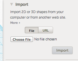
- Open a new model in Tinkercad
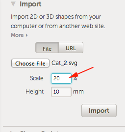
- Click Import, select file, scale the file
- Download and print
New York State Learning Standards
Mathematics, Science, and Technology
-
STANDARD 1
Analysis, Inquiry, and Design: ENGINEERING DESIGN
Key Idea 1: details
Engineering design is an iterative process involving modeling and optimization (finding the best solution within given constraints); this process is used to develop technological solutions to problems within given constraints. (Note: The design process could apply to activities from simple investigations to long-term projects.)
Elementary
| 1.1 | Describe objects, imaginary or real, that might be modeled or made differently and suggest ways in which the objects can be changed, fixed, or improved | |
| 1.2 | Investigate prior solutions and ideas from books, magazines, family, friends, neighbors, and community members | |
| 1.3 | Generate ideas for possible solutions, individually and through group activity; apply age-appropriate mathematics and science skills; evaluate the ideas and determine the best solution; and explain reasons for the choices | |
| 1.4 | Plan and build, under supervision, a model of the solution using familiar materials, processes, and hand tools | |
| 1.5 | Discuss how best to test the solution; perform the test under teacher supervision; record and portray results through numerical and graphic means; discuss orally why things worked or didn't work; and summarize results in writing, suggesting ways to make the solution better | |
Intermediate
| T1.1 | Identify needs and opportunities for technical solutions from an investigation of situations of general or social interest. | |
| T1.1a | Identify a scientific or human need that is subject to a technological solution which applies scientific principles | √ |
| T1.2 | Locate and utilize a range of printed, electronic, and human information resources to obtain ideas. | √ |
| T1.2a | Use all available information systems for a preliminary search that addresses the need. | √ |
| T1.3 | Consider constraints and generate several ideas for alternative solutions, using group and individual ideation techniques (group discussion, brainstorming, forced connections, role play); defer judgment until a number of ideas have been generated; evaluate (critique) ideas; and explain why the chosen solution is optimal. | √ |
| T1.3a | Generate ideas for alternative solutions | √ |
| T1.3b | Evaluate alternatives based on the constraints of design | √ |
| T1.4 | Develop plans, including drawings with measurements and details of construction, and construct a model of the solution, exhibiting a degree of craftsmanship. | √ |
| T1.4a | Design and construct a model of the product or process | √ |
| T1.4b | Construct a model of the product or process | √ |
|
T1.5 | In a group setting, test their solution against design specifications, present and evaluate results, describe how the solution might have been modified for different or better results, and discuss trade-offs that might have to be made. | √ |
| T1.5a | Test a design | √ |
| T1.5b | Evaluate a design | √ |
Commencement
| 1.1 | Initiate and carry out a thorough investigation of an unfamiliar situation and identify needs and opportunities for technological invention or innovation | |
| 1.2 | identify, locate, and use a wide range of information resources including subject experts, library references, magazines, videotapes, films, electronic data bases and online services, and discuss and document through notes and sketches how findings relate to the problem | |
| 1.3 | generate creative solution ideas, break ideas into the significant functional elements, and explore possible refinements; predict possible outcomes using mathematical and functional modeling techniques; choose the optimal solution to the problem, clearly documenting ideas against design criteria and constraints; and explain how human values, economics, ergonomics, and environmental considerations have influenced the solution | |
| 1.4 | develop work schedules and plans which include optimal use and cost of materials, processes, time, and expertise; construct a model of the solution, incorporating developmental modifications while working to a high degree of quality (craftsmanship) | |
| 1.5 | in a group setting, devise a test of the solution relative to the design criteria and perform the test; record, portray, and logically evaluate performance test results through quanitative, graphic, and verbal means; and use a variety of creative verbal and graphic techniques effectively and persuasively to present conclusions, predict impacts and new problems, and suggest and pursue modifications | |
-
STANDARD 2
INFORMATION SYSTEMS
Key Idea 1: details
Information technology is used to retrieve, process, and communicate information as a tool to enhance learning.
Elementary
| 1.1 | Use computer technology,traditional paper-based resources,and interpersonal discussions to learn, do, and share science in the classroom | √ |
| 1.2 | Select appropriate hardware and software that aids in wordprocessing, creating databases, telecommunications, graphing, data display, and other tasks | √ |
| 1.3 | Use information technology to link the classroom to world events | |
Intermediate
| 1.1 | Use a range of equipment and software to integrate several forms of information in
order to create good-quality audio, video, graphic, and text-based presentations. | |
| 1.2 | Use spreadsheets and database software to collect, process, display, and analyze information. Students access needed information from electronic databases and on-line telecommunication services. | |
| 1.3 | Systematically obtain accurate and relevant information pertaining to a particular topic from a range of sources, including local and national media, libraries, muse- ums, governmental agencies, industries, and individuals. | |
| 1.4 | Collect data from probes to measure events and phenomena. | |
| 1.4a | Collect the data, using the appropriate, available tool | |
| 1.4b | Organize the data | |
| 1.4c | Use the collected data to communicate a scientific concept | √ |
| 1.5 | Use simple modeling programs to make predictions. | |
Physics
| 1.1 | Understand and use the more advanced features of word processing, spreadsheets,
and database software. | |
| 1.2 | Prepare multimedia presentations demonstrating a clear sense of audience and
purpose. (Note: Multimedia may include posters, slides, images, presentation software, etc.) | √ |
| 1.2a | Extend knowledge of physical phenomena through independent investigation,
e.g., literature review, electronic resources, library research | |
| 1.2b | Use appropriate technology to gather experimental data, develop models,and
present results | √ |
| 1.3 | Access, select, collate, and analyze information obtained from a wide range of
sources such as research databases, foundations, organizations, national libraries, and electronic communication networks, including the Internet. | |
| 1.3a | Use knowledge of physics to evaluate articles in the popular press on
contemporary scientific topics | |
| 1.4 | Utilize electronic networks to share information. | √ |
| 1.5 | Model solutions to a range of problems in mathematics, science, and technology, using computer simulation software. | √ |
| 1.5a | Use software to model and extend classroom and laboratory experiences,recognizing the differences between the model used for understanding and real-world behavior | √ |
-
STANDARD 5
Technology: Engineering Design
Key Idea 1:
(See Standard 1:ENGINEERING DESIGN)
-
STANDARD 5
Technology: Computer Technology
Key Idea 3: details
Computers, as tools for design, modeling, information processing, communication, and system control, have greatly increased human productivity and knowledge.
Elementary
| 3.1 | Identify and describe the function of the major
components of a computer system. | |
| 3.2 | Use the computer as a tool for generating and drawing
ideas. | √ |
| 3.3 | Control computerized devices and systems through
programming. | √ |
| 3.4 | Model and simulate the design of a complex environment
by giving direct commands. | √ |
Intermediate
| 3.1 | Assemble a computer system including keyboard, central processing unit and disc drives, mouse, modem, printer, and monitor | |
| 3.2 | Use a computer system to connect to and access needed information from various Internet sites | √ |
| 3.3 | Use computer hardware and software to draw and dimension prototypical designs | √ |
| 3.4 | Use a computer as a modeling tool | √ |
| 3.5 | Use a computer system to monitor and control external events and/or systems | √ |
Commencement
| 3.1 | Understand basic computer architecture and describe the function of computer subsystems and peripheral devices | |
| 3.2 | Select a computer system that meets personal needs | |
| 3.3 | Attach a modem to a computer system and telephone line, set up and use communications software, connect to various online networks, including the Internet, and access needed information using email, telnet, gopher, ftp, and web searches | √ |
| 3.4 | Use computer-aided drawing and design (CADD) software to model realistic solutions to design problems | √ |
| 3.5 | Develop an understanding of computer programming and attain some facility in writing computer programs | √ |
-
STANDARD 5
Technology: Technological Systems
Key Idea 4: details
Technological systems are designed to achieve specific results and produce outputs, such as products, structures, services, energy, or other systems.
Elementary
| 4.1 | Identify familiar examples of technological systems that
are used to satisfy human needs and wants, and select
them on the basis of safety, cost, and function. | |
| 4.2 | Assemble and operate simple technological systems,
including those with interconnecting mechanisms to
achieve different kinds of movement. | |
| 4.3 | Understand that larger systems are made up of smaller
component subsystems. | |
Intermediate
| 4.1 | Select appropriate technological systems on the basis of safety, function, cost, ease of operation, and quality of post-purchase support | |
| 4.2 | Assemble, operate, and explain the operation of simple open- and closed-loop electrical, electronic, mechanical, and pneumatic systems | |
| 4.3 | Describe how subsystems and system elements (inputs, processes, outputs) interact within systems | |
| 4.4 | Describe how system control requires sensing information, processing it, and making changes | √ |
Commencement
| 4.1 | Explain why making tradeoffs among characteristics, such as safety, function, cost, ease of operation, quality of post-purchase support, and environmental impact, is necessary when selecting systems for specific purposes | |
| 4.2 | Model, explain, and analyze the performance of a feedback control system | |
| 4.3 | Explain how complex technological systems involve the confluence of numerous other systems | |
-
STANDARD 6
Interconnectedness: Common Themes
SYSTEMS THINKING:
Key Idea 1: details
Through systems thinking, people can recognize the commonalities that exist among all systems and how parts of a system interrelate and combine to perform specific functions.
Elementary
| 1.1 | Observe and describe interactions among components of
simple systems. | √ |
| 1.2 | Identify common things that can be considered to be
systems (e.g., a plant population, a subway system, human beings). | |
Intermediate
| 1.1 | Describe the differences between dynamic systems and
organizational systems. | |
| 1.2 | describe the differences and similarities between
engineering systems, natural systems, and social systems. | |
| 1.3 | Describe the differences between open- and closed-loop
systems. | |
| 1.4 | Describe how the output from one part of a system
(which can include material, energy, or information) can become the input to other parts. | |
Commencement
| 1.1 | Explain how positive feedback and negative feedback
have opposite effects on system outputs. | |
| 1.2 | Use an input-process-output-feedback diagram to model
and compare the behavior of natural and engineered
systems. | |
| 1.3 | Define boundary conditions when doing systems analysis to determine what
influences a system and how it behaves. | |
-
STANDARD 6
Interconnectedness: Common Themes
MODELS:
Key Idea 2: details
Models are simplified representations of objects, structures, or systems used in analysis, explanation, interpretation, or design.
Elementary
| 2.1 | Analyze,construct,and operate models in order to discover attributes of the real thing | √ |
| 2.2 | Discover that a model of something is different from the real thing but can be used to study the real thing
| √ |
| 2.3 | Use different types of models, such as graphs,sketches,diagrams,and maps,to represent various aspects of the real world | |
Intermediate
| 2.1 | Select an appropriate model to begin the search for answers or solutions to a question or problem. | |
| 2.2 | Use models to study processes that cannot be studied directly (e.g., when the real
process is too slow, too fast, or too dangerous for direct observation).
| √ |
| 2.3 | Demonstrate the effectiveness of different models to represent the same thing and
the same model to represent different things. | |
Physics
| 2.1 | Revise a model to create a more complete or improved representation of the
system. | |
| 2.2 | Collect information about the behavior of a system and use modeling tools to
represent the operation of the system.
| √ |
| 2.2a | Use observations of the behavior of a system to develop a model | |
| 2.3 | Find and use mathematical models that behave in the same manner as the
processes under investigation. | |
| 2.3a | Represent the behavior of real-world systems,using physical and mathematical
models | √ |
| 2.4 | Compare predictions to actual observations, using test models.
| √ |
| 2.4a | Validate or reject a model based on collated experimental data | √ |
| 2.4b | Predict the behavior of a system,using a model | √ |
-
STANDARD 7
Interdisciplinary Problem Solving
STRATEGIES:
Key Idea 2: details
Solving interdisciplinary problems involves a variety of skills and strategies, including effective work habits; gathering and processing information; generating and analyzing ideas; realizing ideas; making connections among the common themes of mathematics, science, and technology; and presenting results.
Physics
| 2.1 | Collect,analyze,interpret,and present data,using appropriate tools | √ |
| 2.2 | When students participate in an extended,culminating mathematics,science,and
technology project, then students should: |
| | Work effectively—Contributing to the work of a brainstorming group, laboratory partnership, cooperative learning group, or project team; planning procedures; identify and managing responsibilities of team members; and staying on task, whether working alone or as part of a group.
| √ |
| | Gather and process information —Accessing information from printed media, electronic data bases, and community resources and using the information to develop a definition of the problem and to research possible solutions. | √ |
| | Generate and analyze ideas — Developing ideas for proposed solutions, investigating ideas, collecting data, and showing relationships and patterns in the data. | √ |
| | Observe common themes—Observing examples of common unifying themes, applying them to the problem, and using them to better understand the dimensions of the problem. | √ |
| | Realize ideas—Constructing components or models, arriving at a solution, and evaluating the result.
| √ |
| | Present results—Using a variety of media to present the solution and to communicate the results. | √ |
CDOS
Standard 2: Integrated Learning
details
Students will demonstrate how academic knowledge and skills are applied in the workplace and other settings.
Integrated learning encourages students to use essential academic concepts, facts, and procedures in applications related to life skills and the world of work. This approach allows students to see the usefulness of the concepts that they are being asked to learn and to understand their potential application in the world of work.
Elementary
| 2.1 | Identify academic knowledge and skills that are required
in specific occupations | |
| 2.2 | Demonstrate the difference between the knowledge of a
skill and the ability to use the skill | √ |
| 2.3 | Solve problems that call for applying academic
knowledge and skills. | √ |
Intermediate
| 2.1 | Apply academic knowledge and skills using an interdisciplinary approach to demonstrate the relevance of how these skills are applied in work-related situations in local, state, national, and international communities | |
| 2.2 | Solve problems that call for applying academic knowledge and skills | √ |
| 2.3 | Use academic knowledge and skills in an occupational context, and demonstrate the application of these skills by using a variety of communication techniques (e.g., sign language, pictures, videos, reports, and technology). | |
Commencement
| 2.1 | Demonstrate the integration and application of academic
and occupational skills in their school learning, work,
and personal lives. | |
| 2.2 | Use academic knowledge and skills in an occupational
context, and demonstrate the application of these skills by using a variety of communication techniques (e.g., sign language, pictures, videos, reports, and technology) | |
| 2.3 | Research, interpret, analyze, and evaluate information and experiences as related to academic knowledge and technical skills when completing a career plan. | |
Standard 3a: Universal Foundation Skills
details
Students will demonstrate mastery of the foundation skills and competencies essential for success in the workplace.
Thinking skills
Thinking skills lead to problem solving, experimenting, and focused observation and allow the application of knowledge to new and unfamiliar situations.
Elementary
| 3.2.1 | Use ideas and information to make decisions and solve
problems related to accomplishing a task.
| √ |
Intermediate
| 3.2.1 | Evaluate facts, solve advanced problems, and make
decisions by applying logic and reasoning skills.
| √ |
Commencement
| 3.2.1 | Demonstrate the ability to organize and process
information and apply skills in new ways.
| √ |
- Technology
Technology is the process and product of human skill and ingenuity in designing and creating things from available resources to satisfy personal and societal needs and wants.
Elementary
| 3.5.1 | Demonstrate an awareness of the different types of
technology available to them and of how technology affects society.
| |
Intermediate
| 3.5.1 | Select and use appropriate technology to complete a task.
| √ |
Commencement
| 3.5.1 | Apply their knowledge of technology to identify and solve
problems.
| √ |
- Managing Resources
Using resources includes the application of financial and human factors, and the elements of time and materials to successfully carry out a planned activity.
Elementary
| 3.7.1 | Demonstrate an awareness of the knowledge, skills,
abilities, and resources needed to complete a task.
| √ |
Intermediate
| 3.7.1 | Understand the material, human, and financial resources
needed to accomplish tasks and activities.
| √ |
Commencement
| 3.7.1 | Allocate resources to complete a task.
| √ |
- Systems
Systems skills include the understanding of and ability to work within natural and constructed systems.
Elementary
| 3.8.1 | Demonstrate understanding of how a system operates
and identify where to obtain information and resources within the system.
| √ |
Intermediate
| 3.8.1 | Understand the process of evaluating and modifying
systems within an organization.
| √ |
Commencement
| 3.8.1 | Demonstrate an understanding of how systems
performance relates to the goals, resources, and functions of an organization.
| √ |
Standard 3b: Career Majors
details
Students who choose a career major will acquire the career-specific technical knowledge/skills necessary to progress toward gainful employment, career advancement, and success in postsecondary programs.
- Engineering/Technologies
Core, Specialized and Experiential
| 3b.1 | Foundation Development—Develop practical understanding of engineering
technology through reading, writing, sample problem solving, and employment experiences.
| |
| 3b.2 | Technology—Demonstrate how all types of engineering/technical
organizations, equipment (hardware/software), and well-trained human resources assist and expedite the production/distribution of goods and services
| |
| 3b.3 | Engineering/Industrial Processes—Demonstrate knowledge of planning, product
development and utilization, and evaluation that meets the needs of industry.
| |