Create a 3D model that fits inside an empty toy 2" gumball capsule.
 Measure the capsule. Whatever you model should fit inside.
Toy Car
- Search the internet and find a side view of a car that you find appealing. Save the image to the desktop.
- Launch AutoCAD.
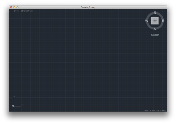
- Create a new drawing. Select File>New Drawing:
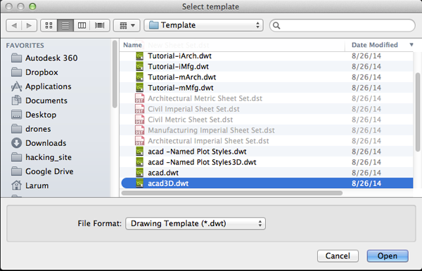
- Select acad.dwt template file and press the Open button to continue to the drawing screen.
- Find the commandline.

If it is not present you should be able to open it it by selecting Window> Command Line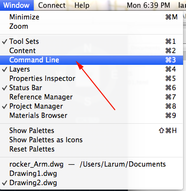
Other ways to display the command line are:
• Pressing Command+3 on Mac, CTRL+9 on Windows.
• Pressing F2
•Typing COMMANDLINE or CLI - You want to set your units to millimeters. Type UN and select UN (UNITS):
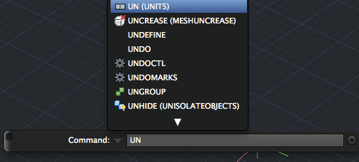
or select Format>Units from the top menu to bring up the Units Dialog box.
Set your units to millimeters: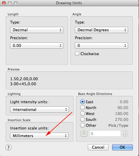 .
.
- You want to create a resolution appropriate for 3D printing. Type FACETRES and set it to 10.
- Make sure your profiles are not deleted after you use them. Type DELOBJ. Set the value to 0.
- In the top left corner set the Custom Visual style to Wireframe.
- Autodesk, like Photoshop has layers. Type LAYER (LA) to initiate the command
or select Window>Layers or press Command+4 (Mac):

This will bring up the Layer Properties Manager Palette:
- Click the New Layer Button.
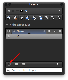
- Name the new layer image (press <RETURN> after typing the name in the field).
- Click the New Layer Button again.

- Name the new layer drawing (press <RETURN> after typing the name in the field).
- Type Properties or PR to open the Properties Inspector
or select Window>Properties Inspector or press Command +5 (Mac)
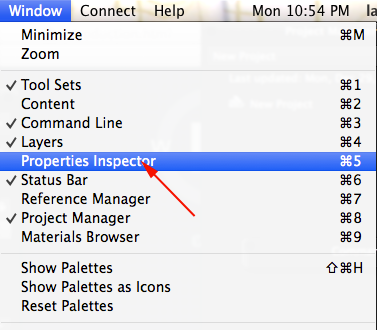
- In the Properties Inspector make the drawing layer's color red:

- To make a layer active, find your layer name in the dropdown list and select it. Make the image layer active.
To move objects to a particular layer, select your object or objects or drag a box around them (if you drag from left to right (→), your selection must include every line. If you you drag from right to left (←) you just need to include part of every segment). Look for the Layer Properties Manager Palette. There is a drop-list there with your layer names. With your objects selected, change the layer to object.

Press the ESC key. If all went well, your object will now be on the selected layer. - To close the Properties Inspector type PROPERTIESCLOSE.
- Type ATTACH and navigate to the profile of your car.
- Click on a point where you want to place your image then drag a box to orient it.
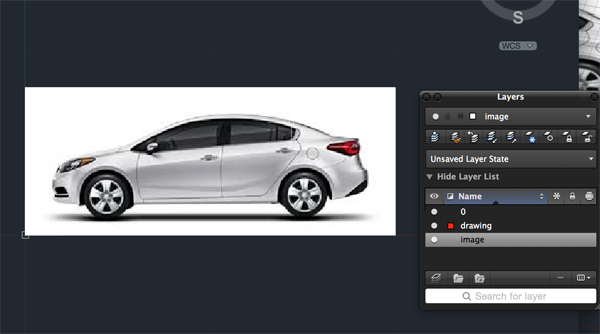
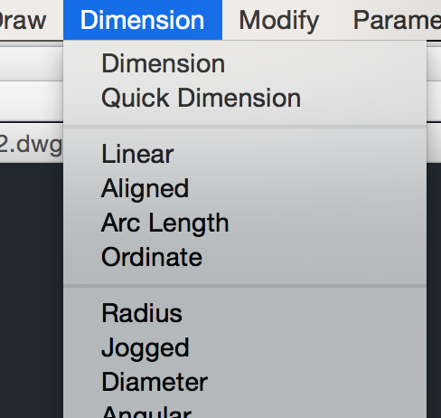
- Click on the Dimension menu and select Linear. Click on one side of the car and then the other.
Make sure the car is the correct size to fit inside the gumball capsule.
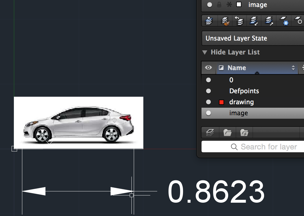
- If you can't read the dimension select Format>Dimension Style.
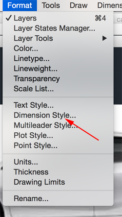
- From the dropdown select Modify
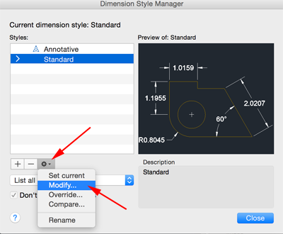
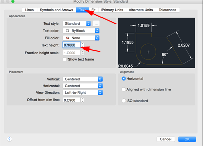
- Select Text. Change the text size to 1.
- If you need to change the size of the car determine the scale ratio by dividing what you want by what you have.
Type SCALE and press RETURN. Click on the image and press RETURN . Click on the left side of the image to establish a base point.
Type your scale factor and press RETURN.
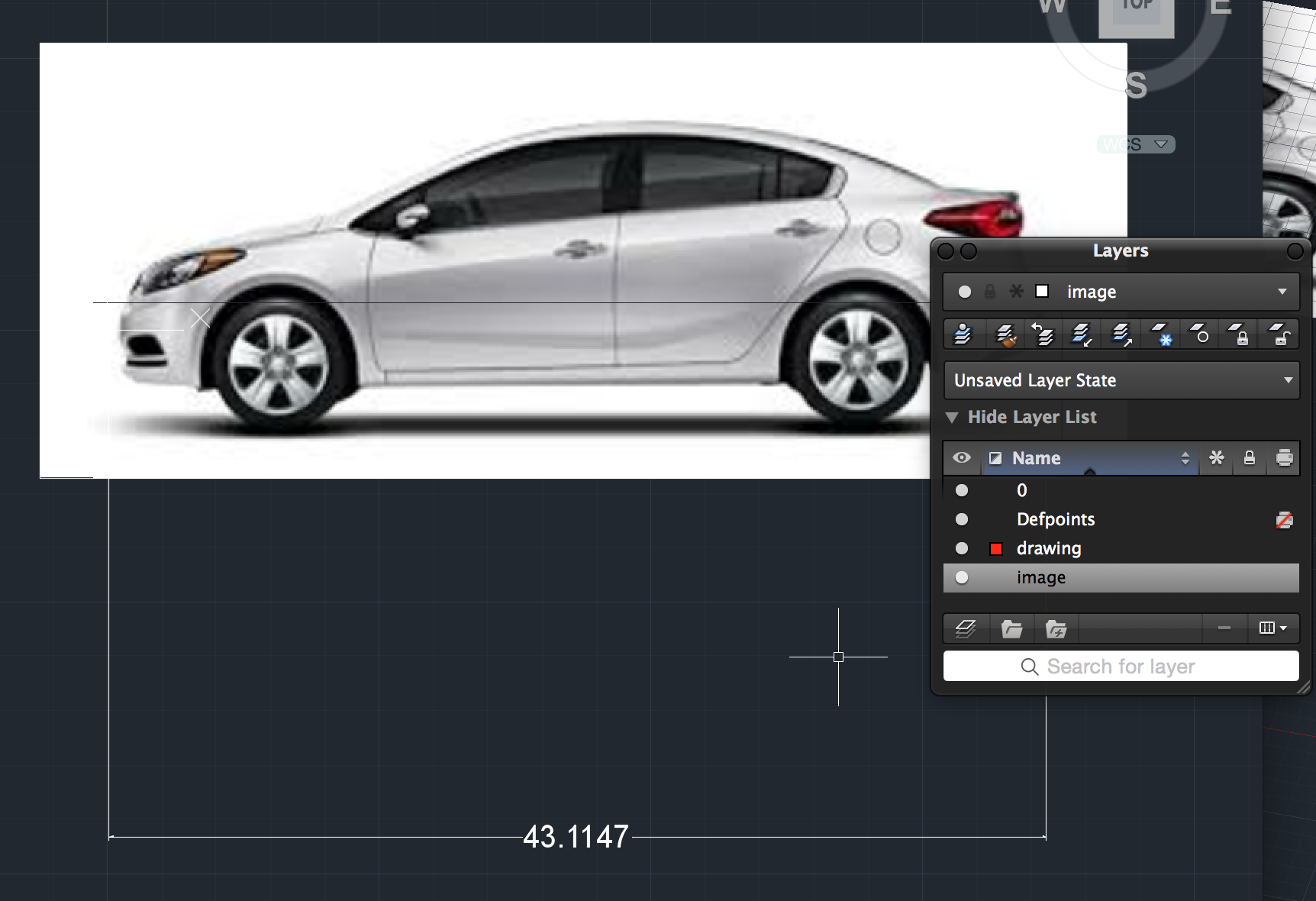
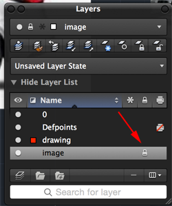
- In the Layer palette lock the image.
- Make the drawing layer active.
- Disable ORTHO and OSNAPS on the Status bar.
-
Type PLINE and trace the outline of the car, but do not include the wheels:
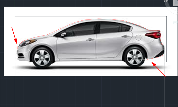
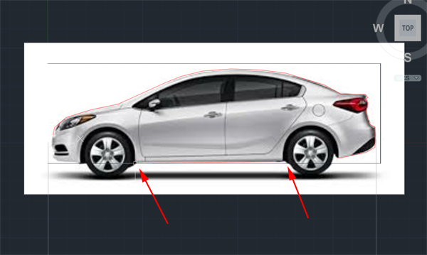
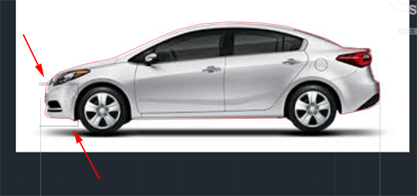
- Type C for circle and click and drag a circle that is roughly the tire size:
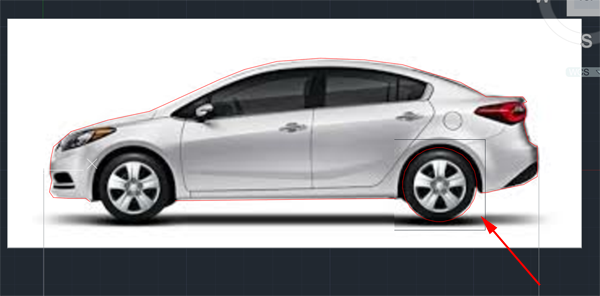
- Type OFFSET and press RETURN. Type .8 and press RETURN. Select the circle and click on the outside of it.
Type OFFSET again and press RETURN. Type 1.6 and press RETURN. Select the second circle and click on the outside of it:
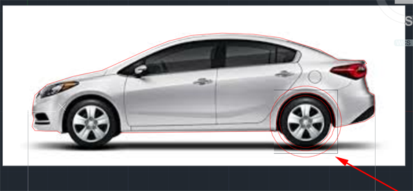
- Type CO for COPY and press RETURN. Select the three circles and press RETURN. Click on the center of the circles then click where you want the center of the other wheel to be:
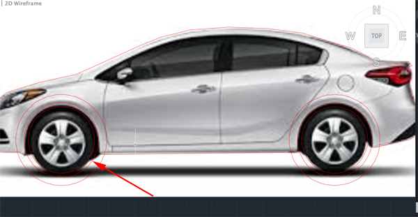
- Type TR for TRIM and press RETURN. Click on the two larger circles and press RETURN:
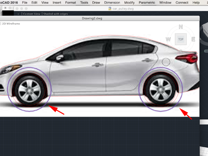
- Click on the outline of the car that is inside the large circles. The lines should disappear:
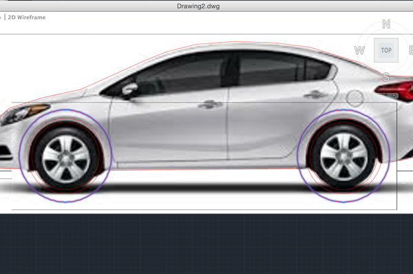
- Type TR again and press RETURN. This time click on the lines that outline the car. Press RETURN and then click on the tops of the large circles to delete them:
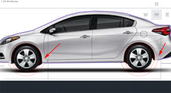
- Type PE for PEDIT and press RETURN. You want to make the outline a closed shape. Type M for multiple and press RETURN. Click on all the lines that make up the outline. Press RETURN.
Press RETURN again then type J for Join and press RETURN until the command line clears:
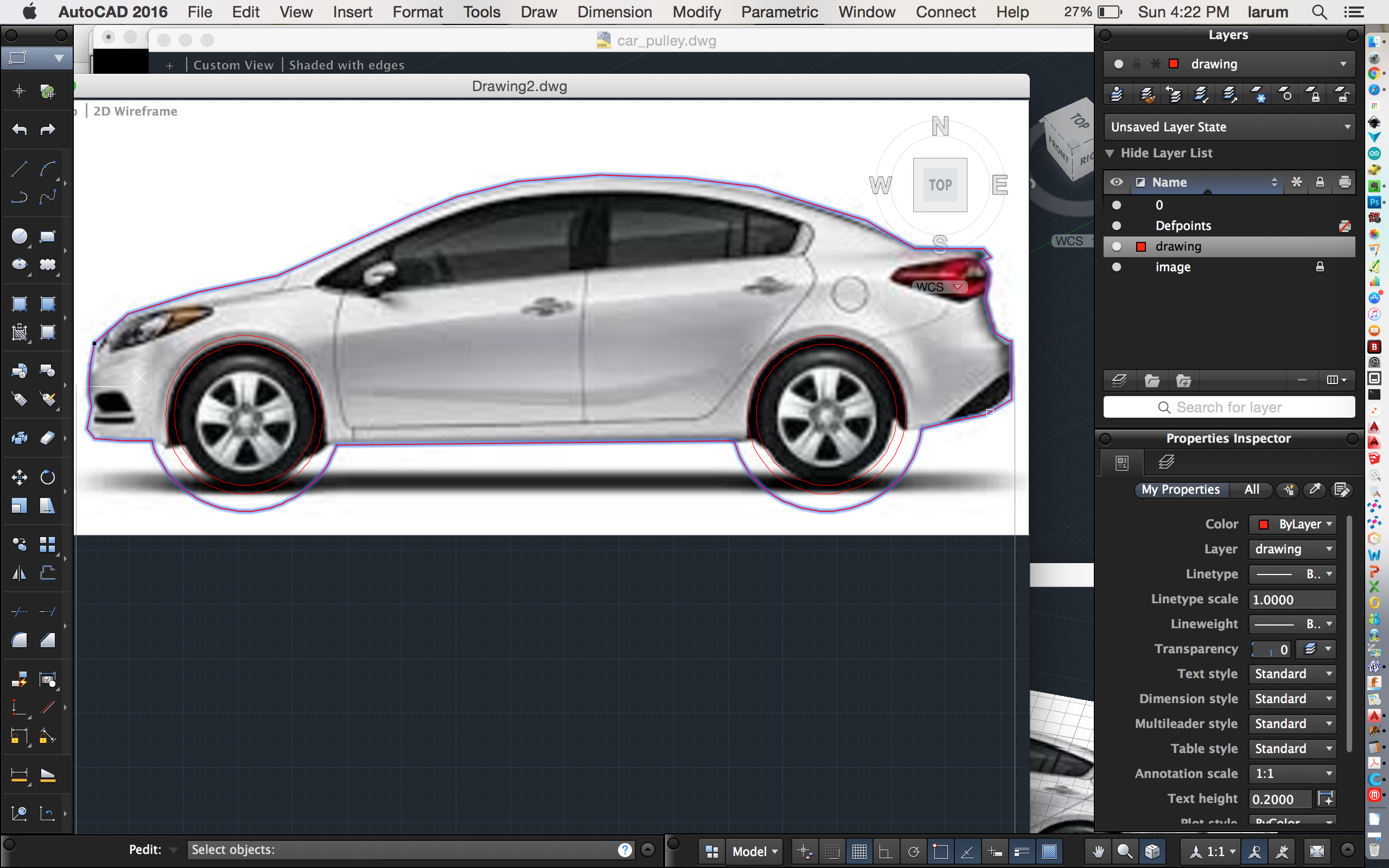
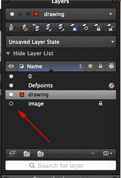
- Turn off your guide image and change the view setting to Shaded with Edges:
- Type OFFSET and press RETURN. Type 1.6 and press RETURN. Click on the inner circle and then click inside it.
Type OFFSET again and press RETURN. Type .4 and press RETURN. Click on the innermost circle and then click inside it.
Type C and press RETURN. Click on the center of the circles. Drag a diameter out so that the last circle is larger than the curve that is part of the outline. Type M for MOVE and press RETURN. Move the smallest and largest circles and move the copy away from the car:
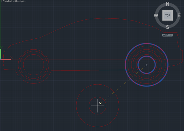
- Type PRESSPULL and press RETURN. Move your cursor between the two inner circles. When they are both highlighted press M for multiple and repeat the process for the other tire.
Press RETURN. Then type 21.2 and press RETURN:
Type PRESSPULL again and press RETURN. Move your cursor to the next circle. When it is highlighted press M for multiple and repeat the process for the other tire. Press RETURN. Then type 20 and press RETURN:
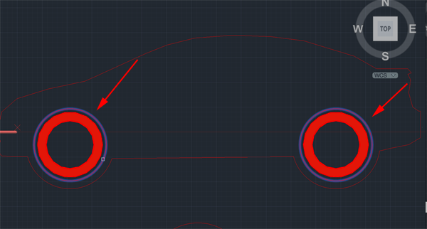
- CTRL+click and select PRESSPULL. Move your cursor over the outline of the car.
When it is highlighted press RETURN. Type 20 and press RETURN:
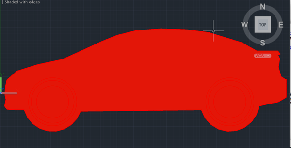
- Use the view cube in the top right corner to adjust your view:
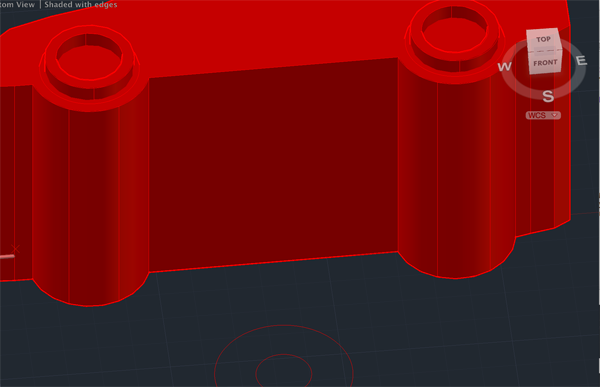
- Type SUBTRACT and press RETURN. Click on the car, press RETURN. Click on the cylinder between the outline and the taller tube. Press RETURN:
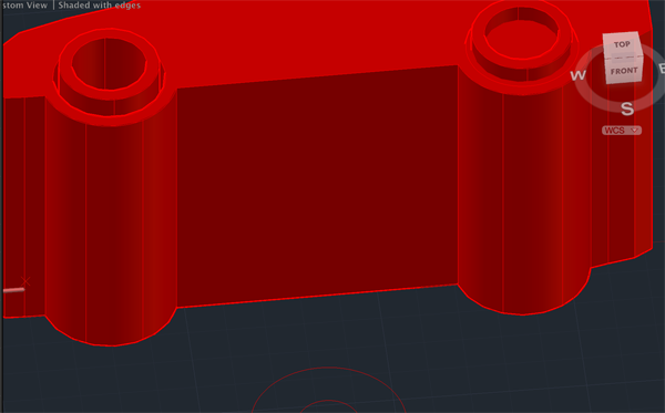
- Subtract the other cylinder and then type PRESSPULL and press RETURN. Clock on the smallest circle and extrude it 7:
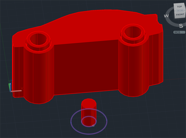
- Call PRESSPULL again and extrude the outer circle 3mm
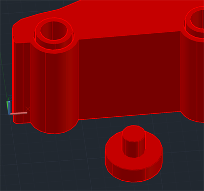
- Type BOX and press RETURN. Click away from the cylinders and press RETURN. Type @10,1 and press RETURN. Type 3 and press RETURN:
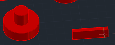
- Type M for MOVE and press RETURN. Click on the box and press RETURN. Select the midpoint on the top face of the box as the first point and the top center of the smaller cylinder for the second point:
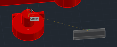
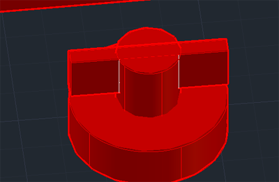
- Call SUBTRACT and remove the box from the cylinder. Make three copies. These will be your wheels that you will pressfit into the axels:
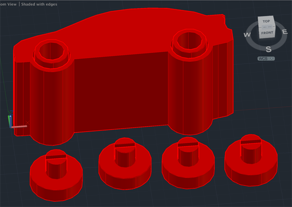
- Type EXPORT and press RETURN. Name your file. Select STL for type and press SAVE. Select your model and press RETURN.
- To save your drawing type SAVEAS and save your drawing either in your work folder or on the desktop. Make sure to name your drawing so that you can find it later.
Logo charm
- Search the internet and find a side view of a car that you find appealing. Save the image to the desktop.
- Launch AutoCAD.
- Create a new drawing. Select File>New Drawing:

- Select acad.dwt template file and press the Open button to continue to the drawing screen.

- Find the commandline.

If it is not present you should be able to open it it by selecting Window> Command Line
Other ways to display the command line are:
• Pressing Command+3 on Mac, CTRL+9 on Windows.
• Pressing F2
•Typing COMMANDLINE or CLI - You want to set your units to millimeters. Type UN and select UN (UNITS):

or select Format>Units from the top menu to bring up the Units Dialog box.
Set your units to millimeters: .
.
- You want to create a resolution appropriate for 3D printing. Type FACETRES and set it to 10.
- Make sure your profiles are not deleted after you use them. Type DELOBJ. Set the value to 0.
- In the top left corner set the Custom Visual style to Wireframe.
- Autodesk, like Photoshop has layers. Type LAYER (LA) to initiate the command
or select Window>Layers or press Command+4 (Mac):

This will bring up the Layer Properties Manager Palette:
- Click the New Layer Button.

- Name the new layer image (press <RETURN> after typing the name in the field).
- Click the New Layer Button again.

- Name the new layer drawing (press <RETURN> after typing the name in the field).
- Type Properties or PR to open the Properties Inspector
or select Window>Properties Inspector or press Command +5 (Mac)

- In the Properties Inspector make the drawing layer's color red:

- To make a layer active, find your layer name in the dropdown list and select it. Make the image layer active.
To move objects to a particular layer, select your object or objects or drag a box around them (if you drag from left to right (→), your selection must include every line. If you you drag from right to left (←) you just need to include part of every segment). Look for the Layer Properties Manager Palette. There is a drop-list there with your layer names. With your objects selected, change the layer to object.

Press the ESC key. If all went well, your object will now be on the selected layer. - To close the Properties Inspector type PROPERTIESCLOSE.
- Type ATTACH and navigate to the profile of your logo.
- Click on a point where you want to place your image then drag a box to orient it.
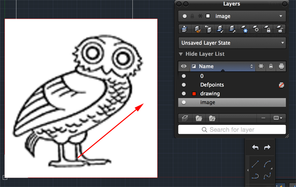
- Click on the Dimension menu and select Linear. Click on one side of the car and then the other.
Make sure the car is the correct size to fit inside the gumball capsule.

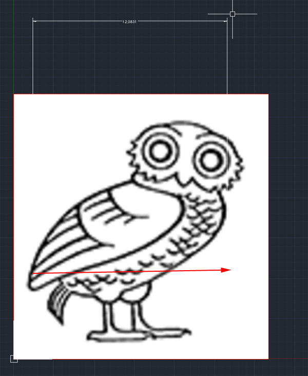
- If you can't read the dimension select Format>Dimension Style.

- From the dropdown select Modify

- Select Text. Change the text size to 1.

- If you need to change the size of the car determine the scale ratio by dividing what you want by what you have.
Type SCALE and press RETURN. Click on the image and press RETURN . Click on the left side of the image to establish a base point.
Type your scale factor and press RETURN.
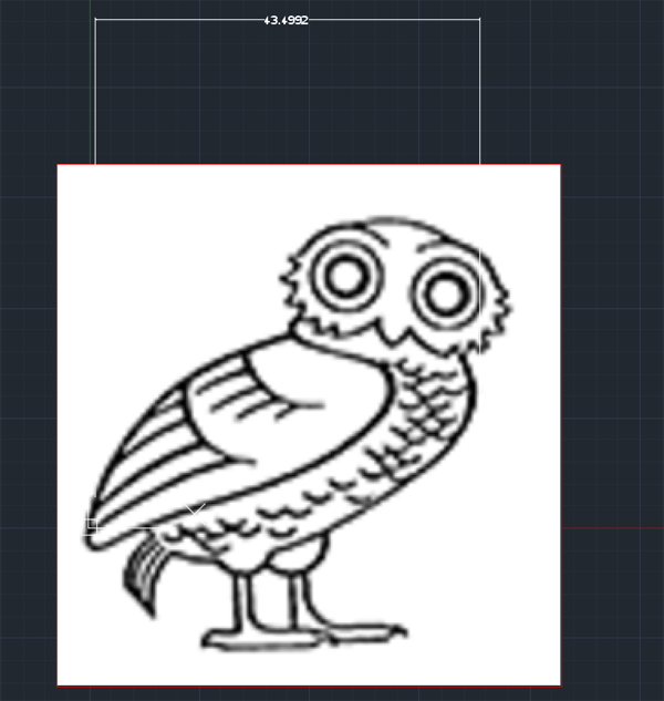
- In the Layer palette lock the image.

- Make the drawing layer active:
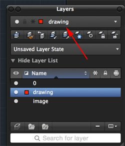
- Disable ORTHO and OSNAPS on the Status bar.
-
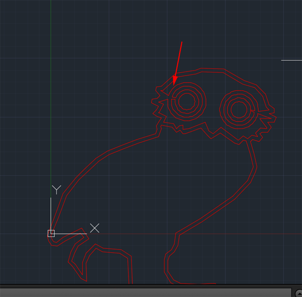
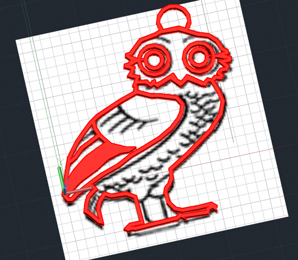
Type PLINE and trace the outline. Once complete add an OFFSET. My offset was .8.
Turn the image on and off as needed: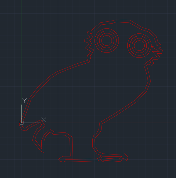
- Make sure there are no unattached parts. Be creative with your connections. Remember to trim:
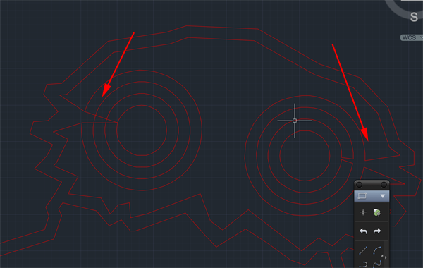
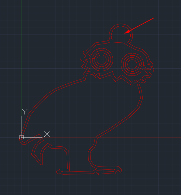
- Add a loop:
I used ARC, but you can use circles, plines, lines or rectangles, etc:
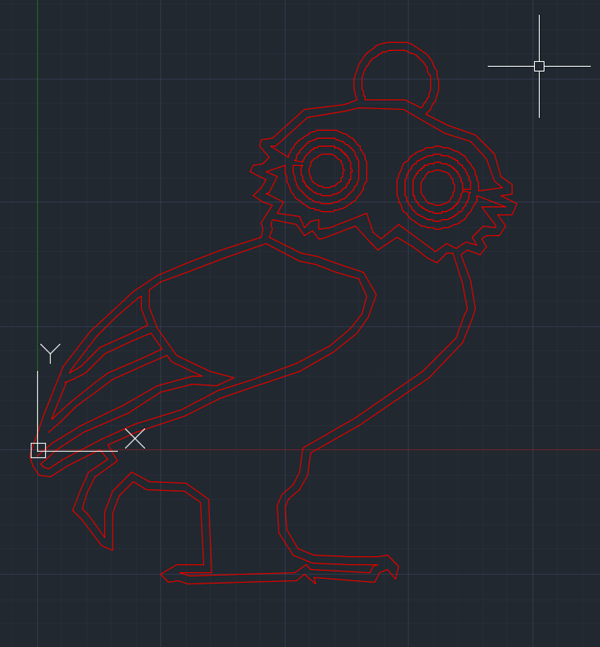
- Continue adding detail. Remmeber you can use EXTEND and TRIM too:
- When you are done, type PE for PEDIT and press RETURN. Type M for multiple and press RETURN. Select All the lines and press RETURN twice. Type J for JOIN and press RETURN until the command line is cleared:
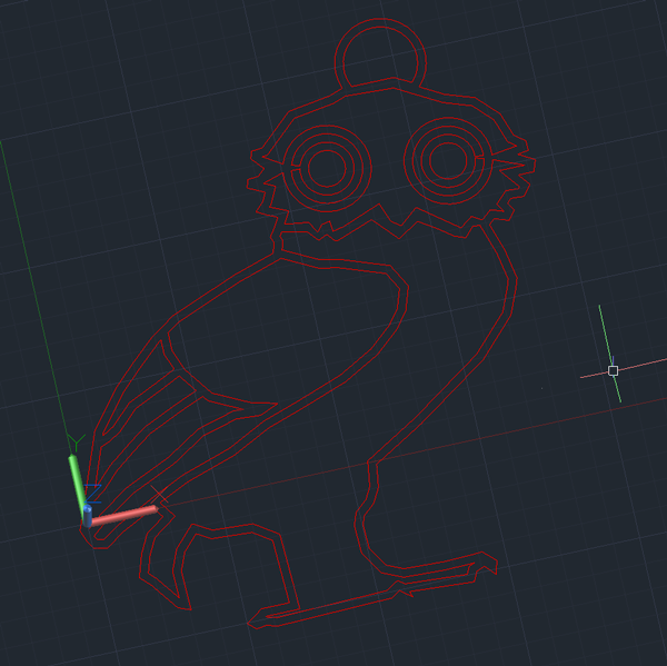
- TYPE VS for VSCURRENT and press RETURN. Type S for Shaded with Edges and press RETURN.
- Type PRESSPULL and press RETURN.
Move your cursor over the lines until everything is highlighted. This might take a bit of trial and error. When Everything is highlighted type the amount you want to extrude and press RETURN:
Coin Trap
- Find a coin (keep it small in size)
- Use the digital calipers to measure the diameter. Make a note of it.
- Launch AutoCAD.
- Create a new drawing. Select File>New Drawing:

- Select acad3d.dwt template file and press the Open button to continue to the drawing screen.
- Find the commandline.

If it is not present you should be able to open it it by selecting Window> Command Line
Other ways to display the command line are:
• Pressing Command+3 on Mac, CTRL+9 on Windows.
• Pressing F2
•Typing COMMANDLINE or CLI - You want to set your units to millimeters. Type UN and select UN (UNITS):

or select Format>Units from the top menu to bring up the Units Dialog box.
Set your units to millimeters: .
.
- You want to create a resolution appropriate for 3D printing. Type FACETRES and set it to 10.
- Make sure your profiles are not deleted after you use them. Type DELOBJ. Set the value to 0.
- In the top left corner set the Custom Visual style to Wireframe.
- Create a box that is at least 5mm larger than the coin's diameter.
Type BOX and press RETURN.
Type 0,0 and press RETURN.
Type the diameter of your coin and at least 5,the diameter of your coin and at least 5 (The box must fit inside the capsule) and press RETURN.
Type the diameter of your coin and at least 5 and press RETURN. - Type VS and press RETURN.
Type 2 for 2dwireframe and press RETURN.
-
Create a cylinder with a diameter less than the coin and a height equal to the box.
Type CYLINDER and press RETURN.
Set the first point to be the center of the top plane of the box and press RETURN.
Type the diameter less than your coin and press RETURN.
Type the negative number that is equal to the height of the box and press RETURN. - CTRL+click on the workarea and select Isolate> Hide Objects.
Click on the box and press RETURN. - Type CO for COPY and press RETURN.
Click on the cylinder and press RETURN.
Click on a point on the cylinder and press RETURN and click on same point and press RETURN again. You now have two copie in the same place. - Open up the Rotate GIZMO. Click on one of the cylinders. Select the green Axis and type 90 and press RETURN. Press ESCAPE to dismiss the GIZMO.
- Make another copy of the vertical cylinder.
- Open up the Rotate GIZMO. Click on one of the cylinders. Select the Red Axis and type 90 and press RETURN. Press ESCAPE to dismiss the GIZMO.
- Combine the cylinders:
Type UNION and press RETURN.
Click on all the cylinders and press RETURN: - CTRL+click on the workarea and select Isolate> End Object Isolation and press RETURN.
- Change the view to 2D Wireframe.
- Create a sphere with a diameter that matches the length, width and height of your box. The center of the sphere should be the center of the box.
- Change the view to Shaded With Edges.
- Subtract the combined cylinders from the box.
- Subtract the sphere from the box.
- Select all the outer edges of the box and apply a 1mm filetedge
- You could also fillet the holes.
- Select the box and export it.
- Make a note of the print time as you'll want to drop the coin in about midway through printing.
Lego Brick
- Launch Autocad and create a new drawing. Set UNITS to Millimeters, FACETRES to 10, DELOBJ to 0. Set the visual style to shaded with edges.
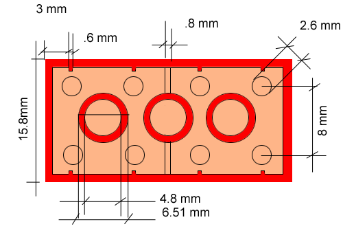
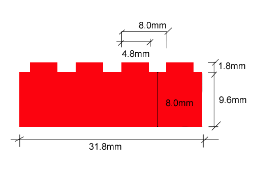
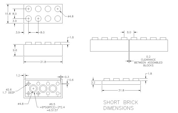
- You are going to draw the box first. Call the BOX command. Set the first point at 0,0. Set the width and length to 31.8, 15.8. Set the height to 9.6
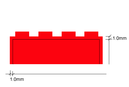
- You need to create an interior box to subtract from the larger box. Call the BOX command. Set the first point at 1.2,1.2. Set the width and length to @29.4, 13.4. Set the height to 8.4
- Set the visual style to wireframe so that you can see both boxes.
- Call SUBTRACT. Select the larger box first, then remove the interior box.
- Set the visual style to Shaded with Edges. Rotate around to make sure the smaller box was subtracted. Return to WCS and click on the HOME icon.
-
You need to create the box in the middle of the brick. Make another box:
- starting at 15.5,1.2,9.6.
- Make the width and length @.8,13.4.
- Make the depth -8.4.
- Call UNION and select everything. This will combine the two boxes.
Making the inside nibs
-
Make a box:
- Starting at 3.6,1.2,0.
- Make the width and length @.6,.3
- Make the height 8.4.
- Set the visual style to WIREFRAME so you can see all the boxes.
- Make a copy of the box you just created.
- Click on the Box to select the object.
- Set the displacement to be 3.9,1.2,0.
- Set the second point to @8,0,0.
- Now you want to copy the two boxes.
- Call the COPY command.
- Select the two boxes.
- Set the displacement to 3.9,1.2,0.
- Set the second point to @0,13.1,0
- Make another box:
- Start at 1.2,3.6,0.
- Make the width and length @.3,.6
- Make the height: 8.4.
- Make a copy of the last box you just created.
- Click on the box you just created to select it.
- Set the displacement to be 1.2,3.9,0.
- Set the second point to @0,8,0
- You want the same configuration of boxes on the other side of the brick. Call the MIRROR command.
Select all the small boxes, Use the midpoints along the length of the brick to create the axis. - Call UNION and select everything.his will combine all the boxes.
Making the cylinders
-
You are going to create the cylinders on the inside of the brick. Make a cylinder.
- Set the center to 15.9,7.9,0.
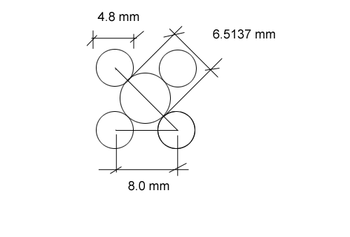
- Set the diameter to 6.5.
- Set the height to 8.4
- M2. Make another cylinder (this will be the interior cylinder).
- Set the center to 15.9,7.9,0.
- Set the diameter to 4.8.
- Set the height to 8.4
- Call COPY. Select both cylinders. Move one copy 8 units to the left and the other 8 units to the right.
- Call SUBTRACT. Select the brick and the larger cylinders as the objects to keep. Select the small cylinders as the objects to remove.
-
You now want to create the cylinders on the top of the brick. Make another cylinder.
- Set the center to 3.9,3.9,9.6.
- Set the diameter to 4.8.
- Set the height to 1.8
- Call COPY. Select the cylinder. Set the displacement at the center and move the copy 8 units up on the Y axis.
- Call COPY again. Select both cylinders. Set the displacement at one of the centers of one of the cylinders. Move one copy 8 units to the right, move another copy 16 units and the last copy 24 units.
- Call UNION and select everything.
Rings
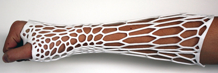 Image from project2gether.com |
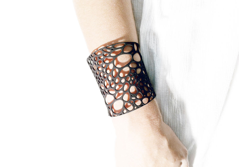 Image from thingfuture.com |
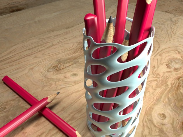
Image from 3dsoup.com |
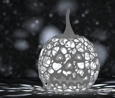 © 3Dizingof.com Image from Adafruit |
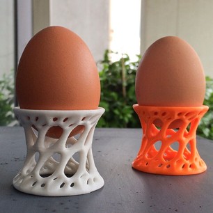
Image from ink361.com |
A Dirichlet tessellation, or Voronoi diagram, is a partitioning of a plane containing a set of points into convex polygons such thatThe individual cells resulting from this process are known as Dirichlet regions, Thiessen polytopes, or Voronoi polygons.
- each polygon contains exactly one generating point
- every point in a given polygon is closer to its generating point than to any other
Voronoi diagrams were considered as early as 1644 by René Descartes and were used in 1850 by Lejeune Dirichlet in the investigation of positive quadratic forms. They were also studied by Georgy Voronoi in 1907. Voronoi diagrams find widespread applications in areas such as computer graphics, epidemiology, geophysics, and meteorology. A particularly notable use of Voronoi diagrams is the analysis of the 1854 Cholera epidemic in London, in which physician John Snow determined a strong correlation between death rates and proximity to the infected Broad Street water pump.
Voronoi Diagrams from the Wolfram Demonstrations Project by Ed Pegg Jr
The Facilities Location Problem from the Wolfram Demonstrations Project by Tim Neuman
Voronoi diagrams have a wide range of uses from calculating the area per tree in the forest, to determining the source of Cholera. In general these diagrams are useful for finding "who is closest to whom." Voronoi diagrams are used:
- Path planning in the presence of obstacles
- Model and analyze plant competition
- Analyzing patterns of urban settlements
- Geometric modeling
- Closest pairs algorithms
- Nearest-neighbor queries
Say you have a map of your city, and on it you have located a set of points representing every fast food restaurant. Creating a Voronoi diagram from these points would enable you (on your walk through the city) to know which restaurant you're closest to at any given time. Of course, an application that simple could be solved more efficiently via other methods, but let's raise the stakes a bit. What if you want to know the percentage of your walk that will be closest to one particular McDonalds. Suddenly, without a Voronoi diagram, this is tricky. With a Voronoi diagram, however, it's a simple matter of intersecting the line that represents your walk with the cell that surrounds that particular restaurant.
Voronoi diagrams can also be used to make maps, not just analyze them. Say you have a set of points that represent air quality sample locations. To quickly generalize the sample points into a local map… bam! Voronoi diagram!
How to Draw A Voronoi Cell
First way: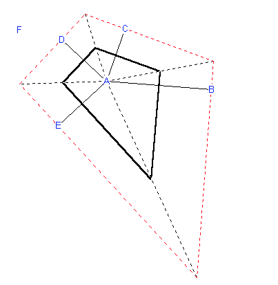
Image frommathforum.org
Start with a figure of six points ABCDE (F comes later). To construct the Voronoi cell of A draw the perpendicular bisectors of segments AB, AC, AD, and AE. These perpendicular bisectors enclose a polygon around point A. In the figure above this polygon is the bold black quadrilateral. Only the sides of this polygon form the cell around A. The rest can be removed (as is done in the figure).
from Second way:
- Input Sites.
- Connect Nearest Neighbors (shortest line wins).
- Find Center Points.
- Draw Perpendicular Bisectors.
- Trace Cells.
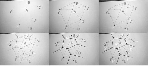
Images from sevensixfive
Use different colors for the input sites, the Delauney lines, and the bisectors.
- The input points, step one, are called sites, labeled here A, B, C, etc.
- Connect the sites to all of their nearest neighbors without making a line that crosses another. This is known technically as the Delauney Triangulation.
- Find and mark the centerpoint of every line on the Delauney graph.
- Draw the perpendicular bisector for each Delauney line. This is where careful accuracy, in finding the centerpoints, and in drawing a tight 90 degree angle, pays off. If everything has been done correctly, there will always be three lines converging at a point, unless the input sites are on a perfectly regular rectangular grid.
- Retrace the outline of each Voronoi cell from the perpendicular bisectors. There will be one cell for every site, and at the end, each cell is just the set of all surface area points that are closer to its site than any of the other sites, as illustrated in the last panel: A' -> A, B' -> B, etc.
Resources
- Wolfram MathWorld
- Wolfram Demonstration Project
- Voronoi Diagrams: Applications from Archaology to Zoology
- zheng3's Meshlab tutorial
- sevensixfiveLHow to: Draw the Voronoi Diagram
- codeproject: Create a Voronoi Diagram
- Mesh—A Processing Library
- Don Havey's Voronoi Diagram tutorial
- Voronoi Encapsulation, Walk Through (How to) using Blender & 3D Printing the result Gareth Chiprobot
Procedure
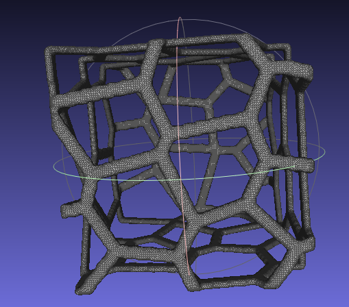
- Open MeshLab
- Import or add a new form:Filters>Create New Mesh Layer>some_form
- Turn on flat lines
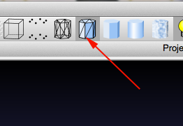
- Enable Layers. This will bring up the Layers sidebar.
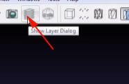
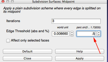
- You want around 300k faces so select Filter>Remeshing>Subdivision surfaces:Loop or midpoint.
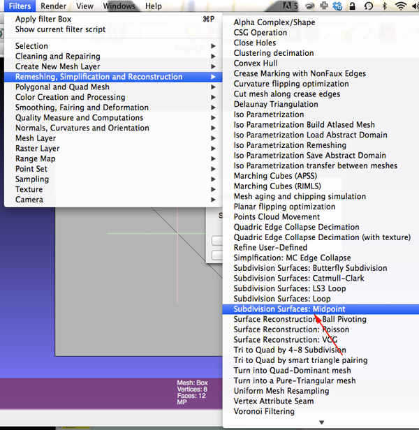
- Change the perc field to .5
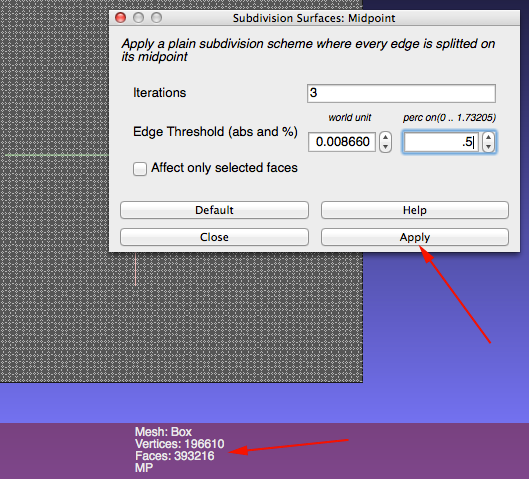
- Keep clicking on Apply until you get close to 300k faces
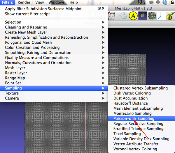
- Select Filter>Sampling>Poisson Disk Sampling
- In the dialog box enter 35
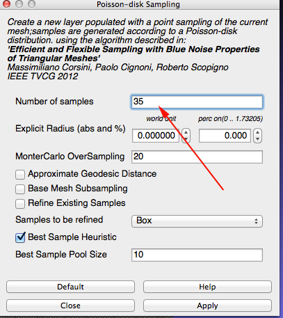
You are looking for about 50 points
The points represent your sites - Select Filter>Sampling>Voronoi Vertex Coloring
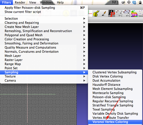
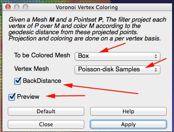
- Make sure your dialog box is set up similar to the one below:
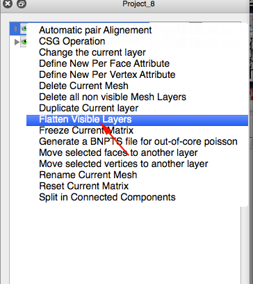
- CTRL+click on the top layer and select Flatten Visible Layers
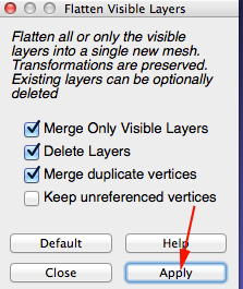
- Apply flatten
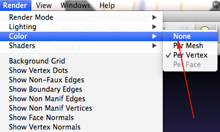
- Remove the interior faces. First click on
Render>Color>None
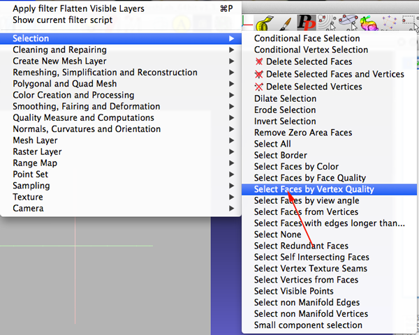
- Select Filters>Selection>Select Faces by Vertex Quality
- Check the Preview checkbox and adjust the sliders
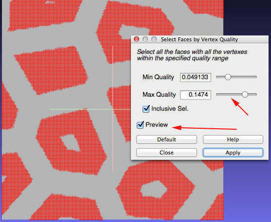
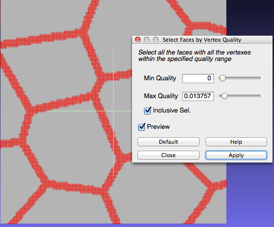
- Keep adjusting until the selection looks the way you want it to. Click apply and then close the selection window.
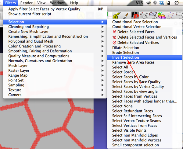
- Select Filter>Selection>Invert Selection
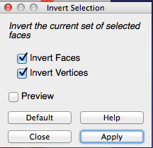
- Apply the Inversion
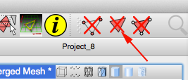
- Click the Delete Faces button.
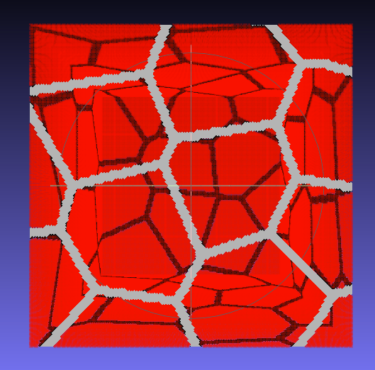
- You should have a single-sided Voronoi mesh.
- Time to refine the mesh. Select Filters>Smoothing, Fairing, and Deformation>Laplacian Smooth.
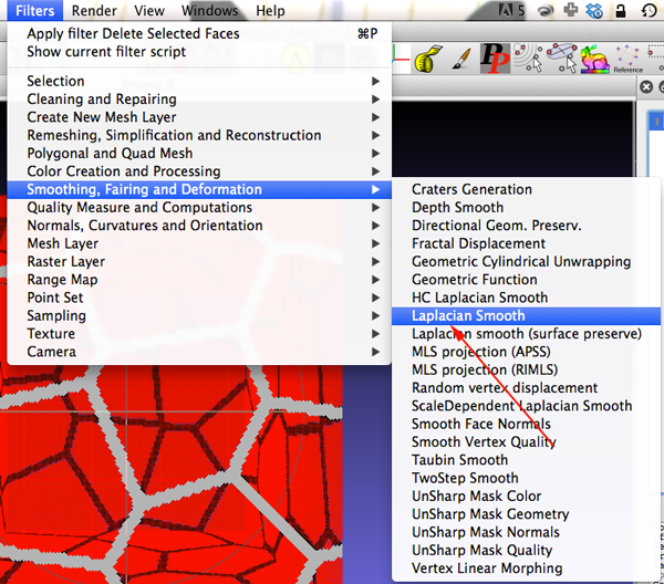
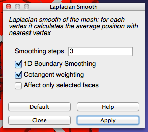
- Apply the filter
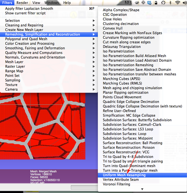
- You still have just a 2D mesh. You need to extrude the mesh. Select Filters>Remeshing, Simplification, and Reconstruction>Uniform Surface Resampling
- Make sure your dialog box looks similar
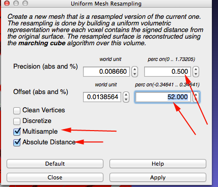
- Click Apply. This will take some time to process. Be patient.
- Turn off the layer that is not the offset layer./li>
- Select the Offset layer. One last smothing algorithm: select Filters>Smoothing, Fairing, and Deformation>Taubin Smooth.
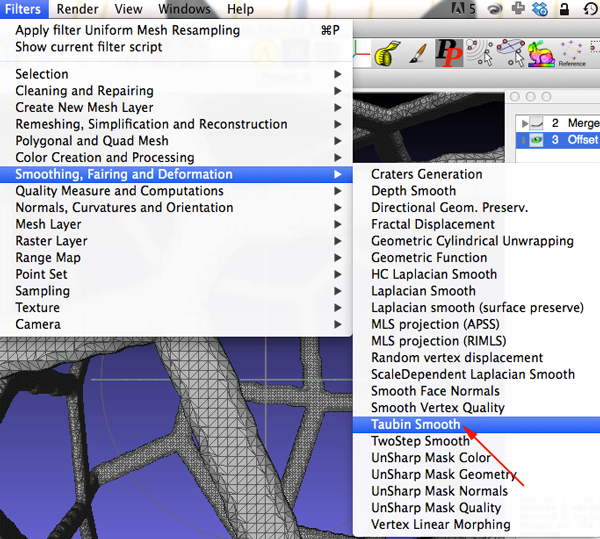
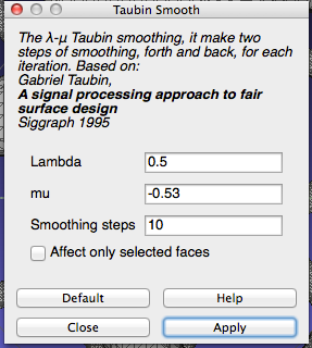
- Keep the defaults and apply Taubin filter
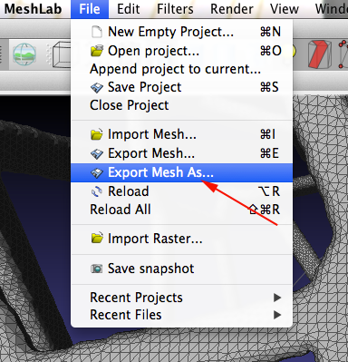
- Export As and save as an STL
TinkerCad
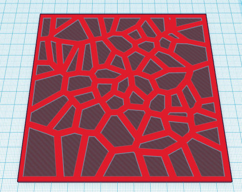
TinkerCad has a Voronoi shape that can be found under Shape Generators To get a similar skeletal effect- Drag the shape on to the workplane.
- Increase the Cell Spacing.
- Convert the shape to a hole.
- Drag a box on to the workplane and adjust the width, length and height so that the voronoi shape can be subtracted from the box

Blender
Version 1

- Open Blender
- If you have not turned on Cell Fracture
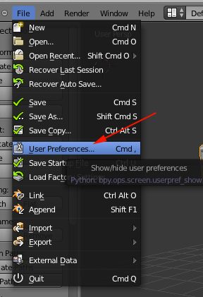
- Open User Preferences
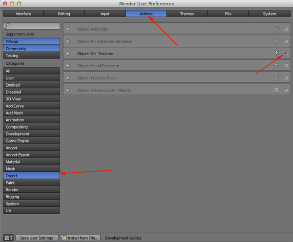
- Click on the Addons
- Search for cell or just click on Objects and enable Cell Fracture
- Click Save User Settings
- Close User Preferences
- Open User Preferences
- Scale your cube to a reasonable printing size or delete it and import another model or add another mesh
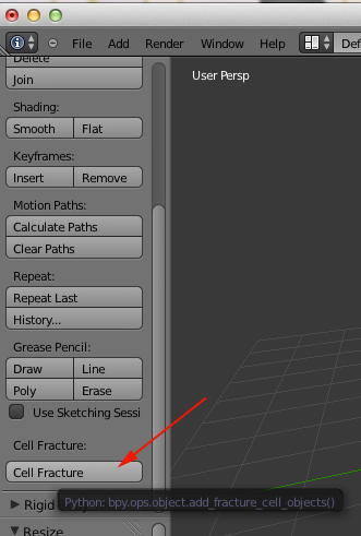
- Click on Cell Fracture
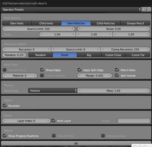
- Go with the defaults or customize:
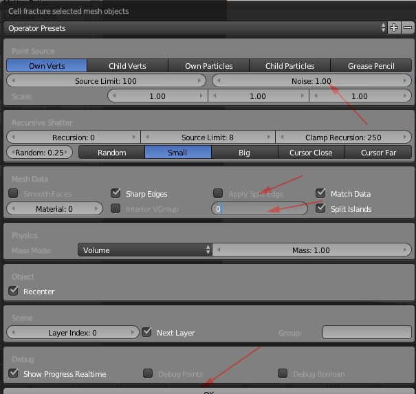
- Click OK
- Click on Layer 2
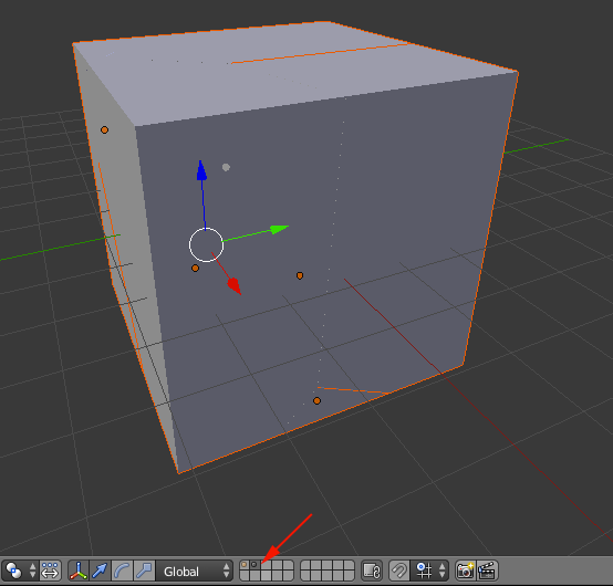
- Click on one of the pieces and press A until all are selected
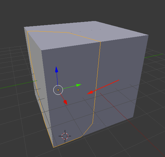
- Press CTRL+J to combine all pieces
- With the object selected navigate to Edit Mode
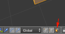
- Enable Face Select
- Select Vertices from Mesh menu and Remove Doubles. Also up the Merge Difference
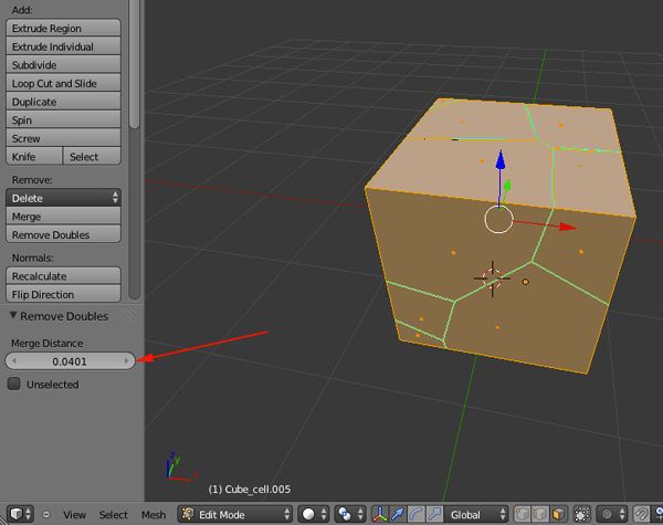
- Press A to deselect and then A to reselect all
- Press X and Delete Only Faces
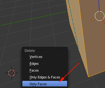
- Select Edges and select all interior edges
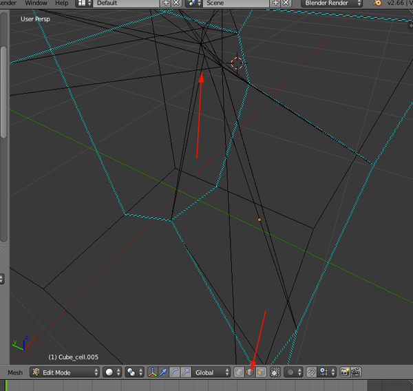
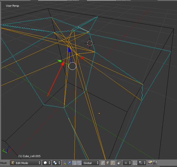
- Delete the selected edges
- Ensure that all interior (black) edges are removed
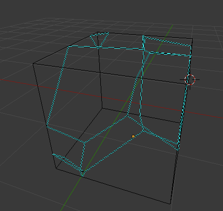
- Select Vertices
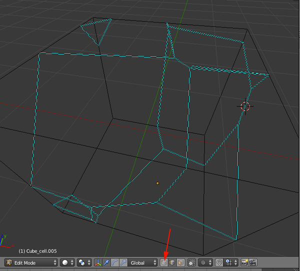
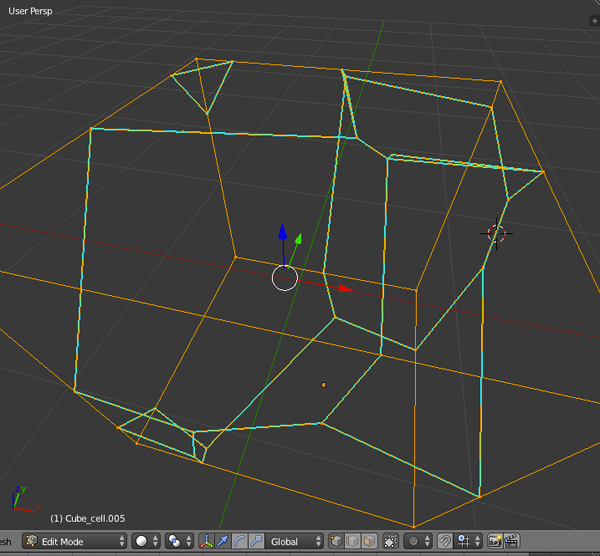
- Select all Vertices by pressing A:
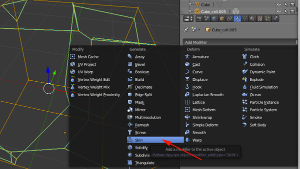
- Select the Skin Modifier
- Press CTRL+A to adjust thickness of mesh
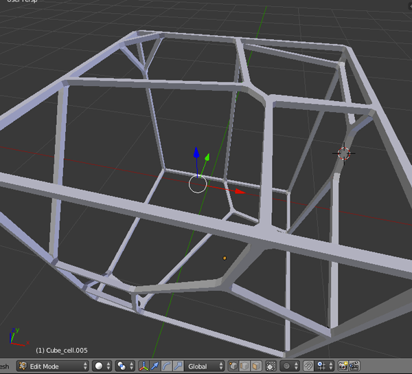
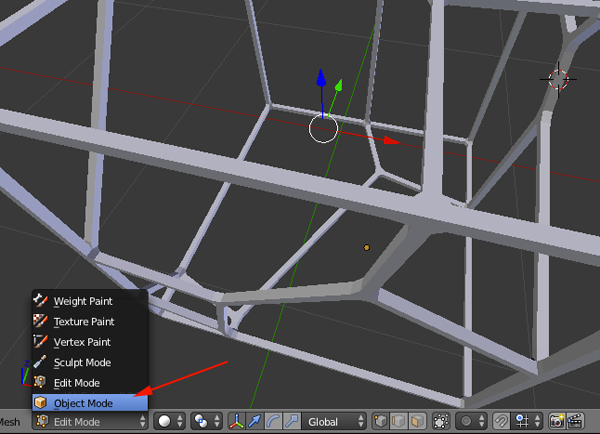
- Navigate to Object Mode (You must be in Object Mode to apply the modifier).
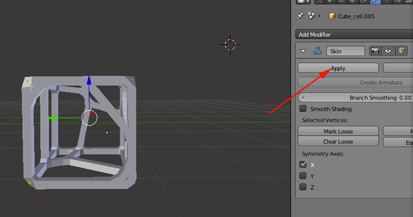
- Apply the Skin Modifier
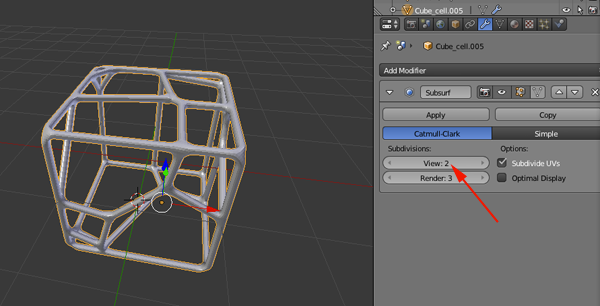
- Apply a Subsurf Modifier
- Under the File menu select Export and select STL
Version 2

- Open Blender
- If you have not turned on Cell Fracture
- Open User Preferences

- Click on the Addons
- Search for cell or just click on Objects and enable Cell Fracture

- Click Save User Settings
- Close User Preferences
- Open User Preferences
- Scale your cube to a reasonable printing size or delete it and import another model or add another mesh
- Click on Cell Fracture

- Go with the defaults or customize:


- Click OK
- Click on Layer 2

- Click on one of the pieces and press A until all are selected

- Press CTRL+J to combine all pieces
- With the object selected navigate to Edit Mode
- Enable Face Select

- PressA to deselect and then A to reselect all
- Press X and Delete Only Faces

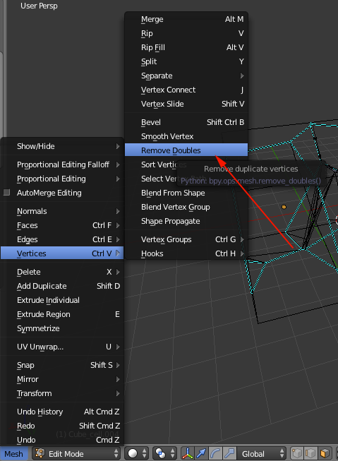
- Select Mesh>Vertices>Remove Doubles
- Navigate back to Object Mode
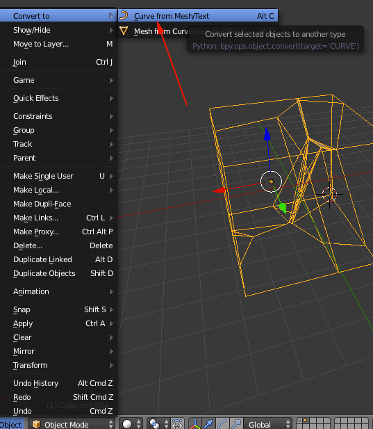
- Select Object>Convert to>Curve from Mesh/Text or press ALT+C
- Press SHIFT+A and select curve>Circle
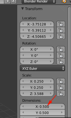
- Resize the circle making it small. You can also press N for better control
- Deselect the circle and select your model
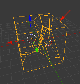
- On the right select Object Data
- Under Bevel Object select the bezier curve. Select Fill Caps and Fill Deformed
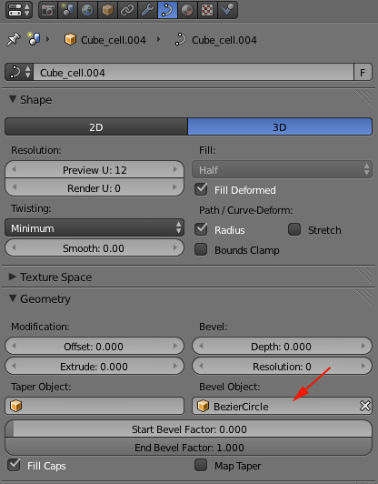
- Select Object>Convert to>Mesh from Curve or press ALT+C
- Under the file menu select Export and select STL
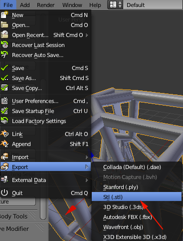
- Chances are you will not have an object that is manifold. Open in NetFabb to repair
Voronoi with Meshmixer
Add a Voronoi pattern to any .STL or 3D model in Autodesk Meshmixer by reducing polygons and applying the [Dual Edges] pattern.- Import model into Meshmixer (file > Import)
- Select entire model using keyboard Ctrl+a or use the [select] tool to click-drag certain parts you want to edit.
- Select Edit > Reduce (SHIFT+R).
- Increase the percentage slider or change drop down to Triangle Budget and lower the count to below 500. Less polygons result in larger openings in your final model. It may help to try a very low polygon count.
- Click [accept].
- Select Edit >Make Pattern
- Change the first drop down to [Dual Edges] (pattern using exterior only) or [Mesh + Delaunay] Dual Edges (generates pattern inside model). Changing [element dimensions] will make thicker or narrower tubes.
- Export .STL
Sphericons
When you rotate a symmetric polygon around a mirror axis, cut the solid into two equal parts and then put the parts back together differently, you produce a sphericon.- Rotating a 5-pointed star about any of its five mirror lines:
- Cut the form in half to reveal the original star cross section.
- Create a new drawing. Select File>New Drawing:

- Select acad.dwt template file and press the Open button to continue to the drawing screen.

- Find the commandline.

If it is not present you should be able to open it it by selecting Window> Command Line
Other ways to display the command line are:
• Pressing Command+3 on Mac, CTRL+9 on Windows.
• Pressing F2
•Typing COMMANDLINE or CLI - You want to set your units to millimeters. Type UN and select UN (UNITS):

or select Format>Units from the top menu to bring up the Units Dialog box.
Set your units to millimeters: .
.
- You want to create a resolution appropriate for 3D printing. Type FACETRES and set it to 10.
- Make sure your profiles are not deleted after you use them. Type DELOBJ. Set the value to 0.
- In the top left corner set the Custom Visual style to Wireframe.
- Draw a bounding rectangle and then draw a odd numbered polygon withing the boundaries:

- Delete the rectangle:
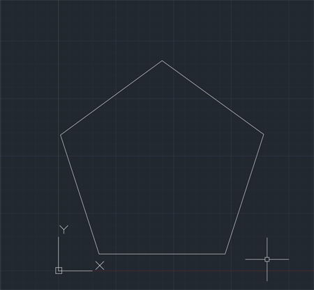
- Use the LINE tool to construct a star:
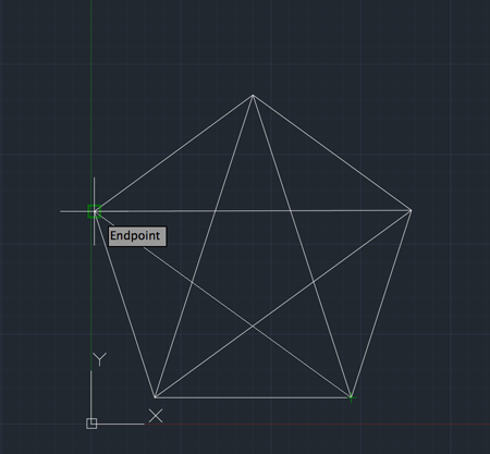
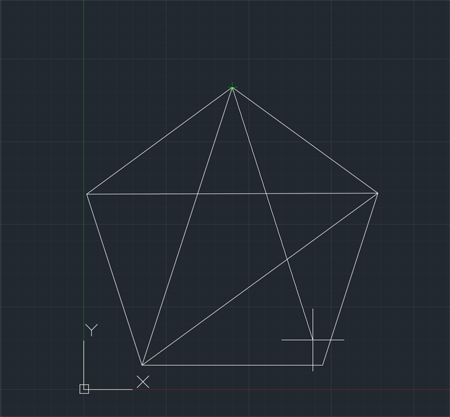
- Use the LINE tool to bisect the star:

- Use TRIM to trim half the star:
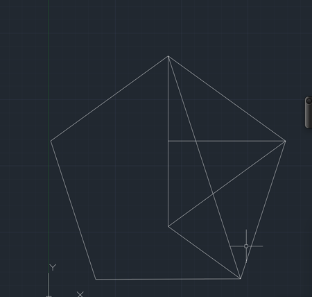
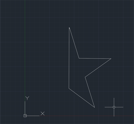
- Turn your shape into a REGION:
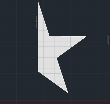
- Use REVOLVE to create a solid from the region. Revolve it 180°:
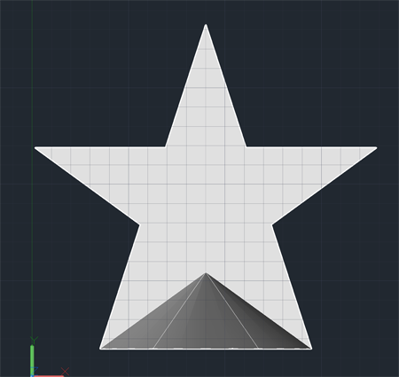
- Change the WCS to align with the face. Use the LINE tool to find the center. Make room for a magnet:
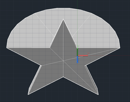
- Make sure you have a hole for your magnet that is .4mm larger in each dimension. Export and print 2.
SketchUp Instructions
Creating your regular polygon in SketchUp:- Open SketchUp. Use the millimeter template. Select the figure and delete it
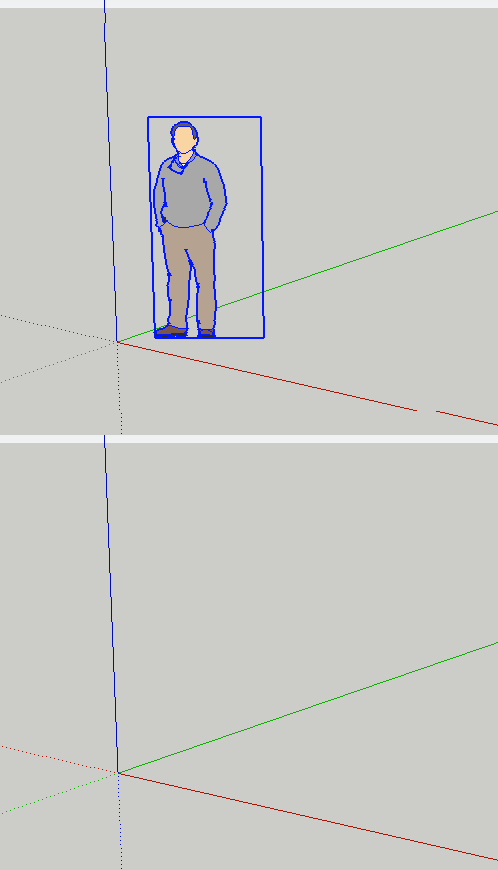
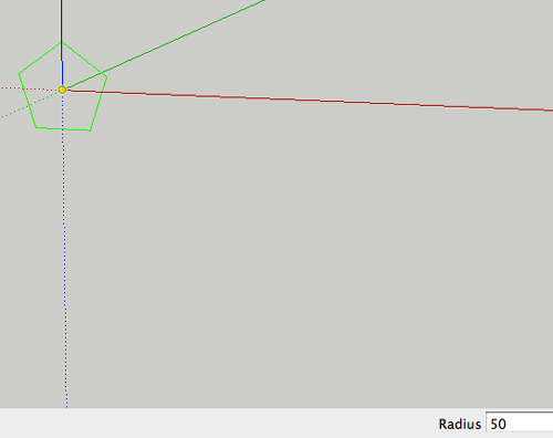
- Create a polygon of 5 sides:
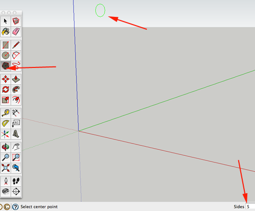
- Hold shift so that the polygon remains green and aligned with the origin:
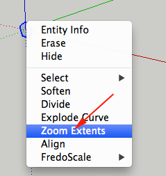
- CTRL+click on the figure and Zoom Extents:
- Select the line tool:
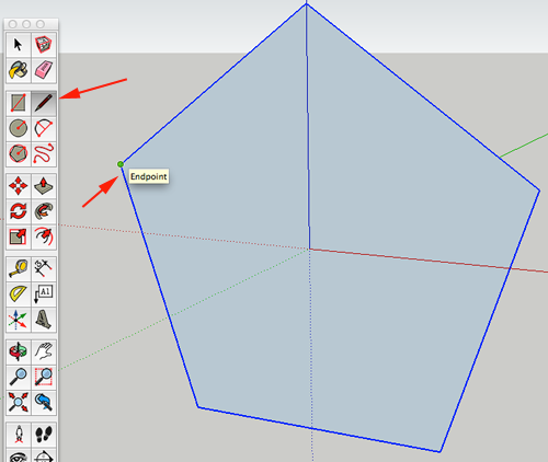
- Connect the endpoints:
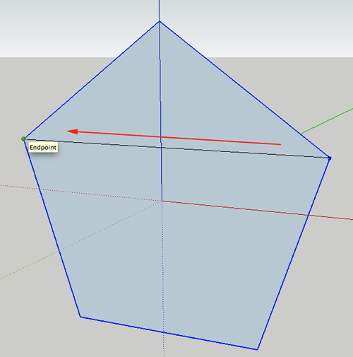
- Continue to connect endpoints:
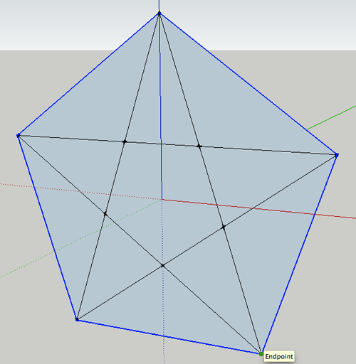
- Delete the excess outer lines:
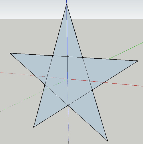
- Select the inner hexagon:
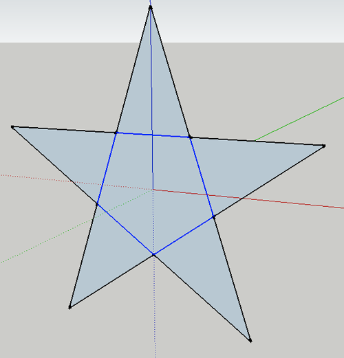
- Delete the selection. Now draw a vertical line:
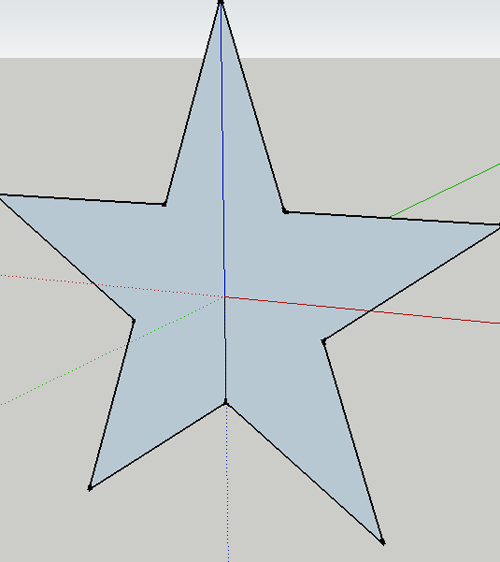
- Select half the figure
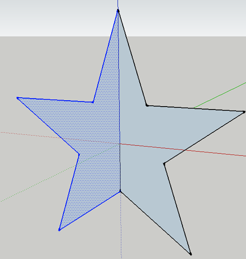
- Delete the selection:
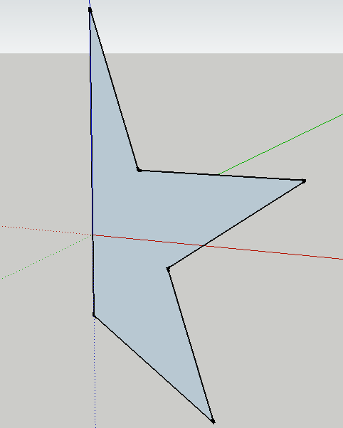
- Select the circle tool and change the sides to 64:
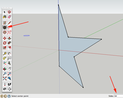
- Draw a circle on the blue axis at the origin. Then select the face of the circle:
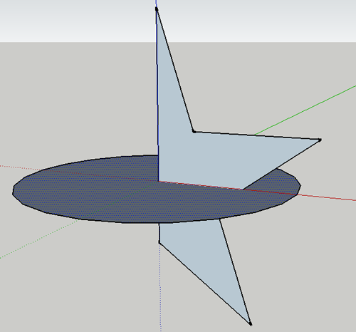
- Click on the Follow Me tool and click on the half of the star:
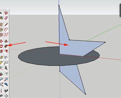
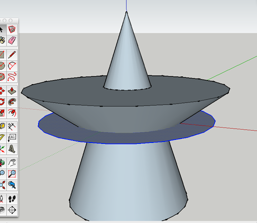
- Delete the circle:
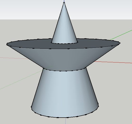
- Triple click on the form:
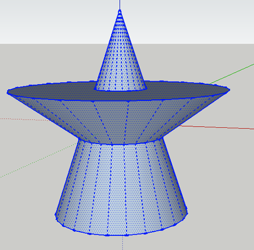
- Select File>Export STL
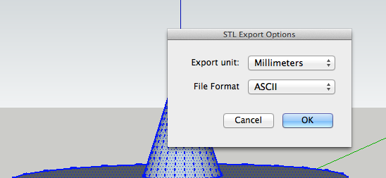
- Name the stl file:

Variations
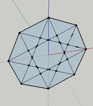
- Here is an eight sided polygon where the line tool connects every third endpoint:
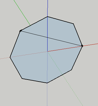
- Continue the pattern:
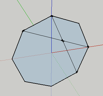
- Continue the pattern:
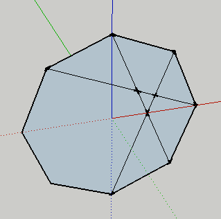
- Completed:
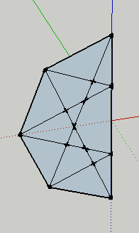
- Delete half:
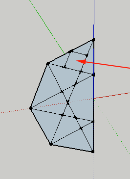
- Add squared at each midpoint:
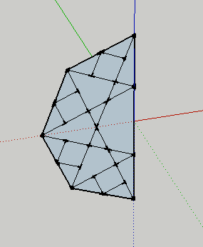
- Continue pattern:
- Delete excess outer lines:
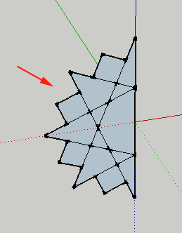
- Delete excess inner lines
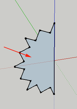
- Create a circle on the blue access and select the face
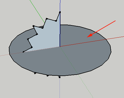
- Click on Follow me and the face of the polygon:
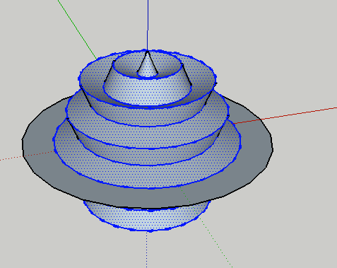
- Delete the circle:
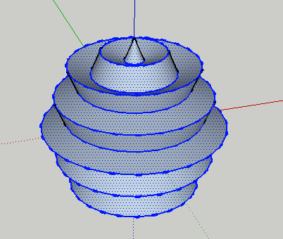
Another variation
- Eight sides, every endpoint connects to every other endpoint:
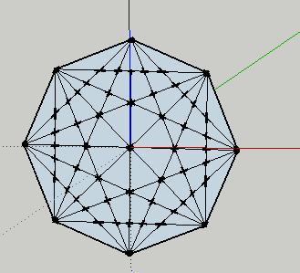
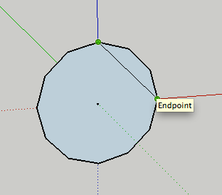
- Here is a twelve sided polygon:
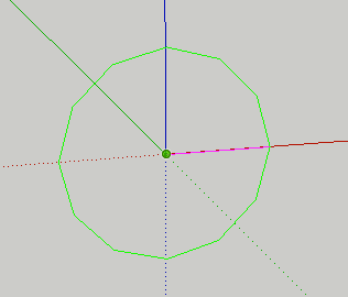
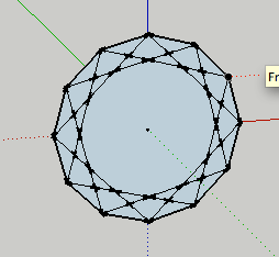
- Connect every third endpoint
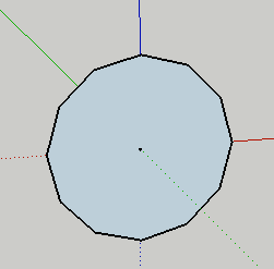
- Continue pattern:
- Or connect every fifth:
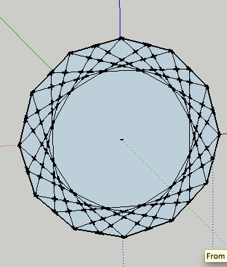
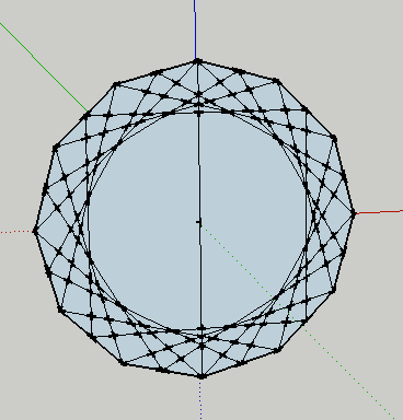
- Select half:
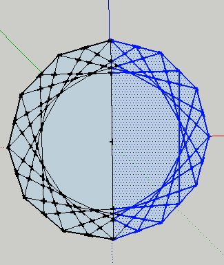
- Delete selection:
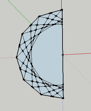
- Delete excess outer and inner lines:
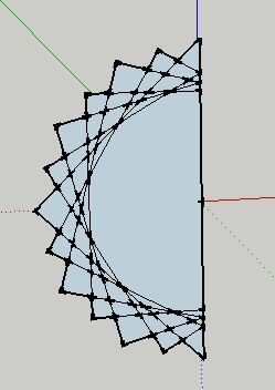
NetFabb
- Open Netfabb
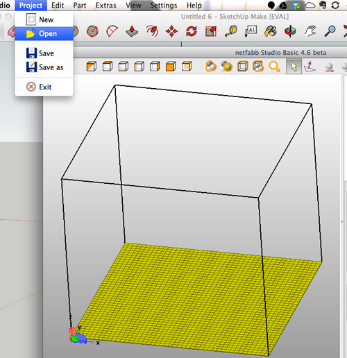
- If necessary, invert:
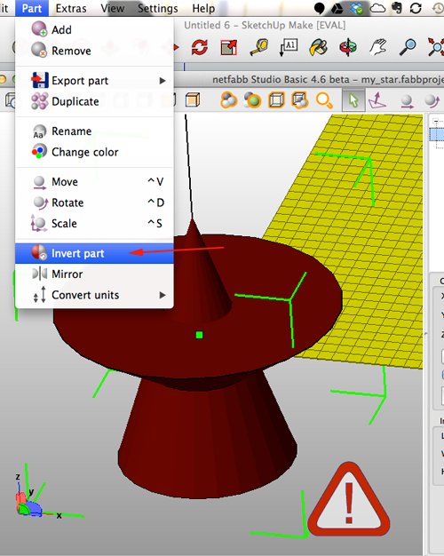
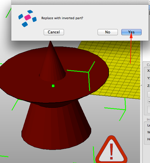
- Move part to absolute 0:
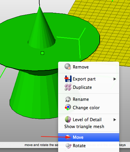
- Look at top view:
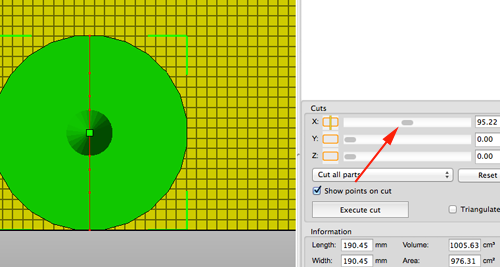
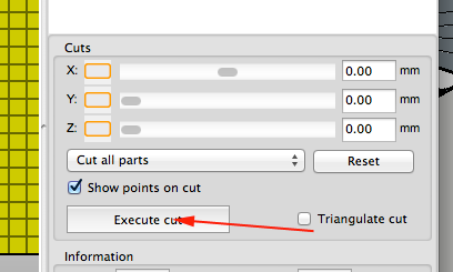
- Execute X cut
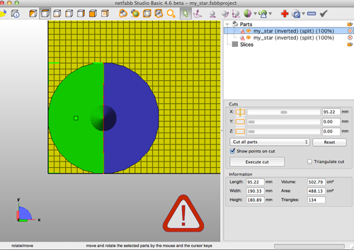
- Select half and repair:
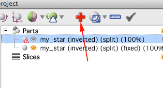
- Click on red cross
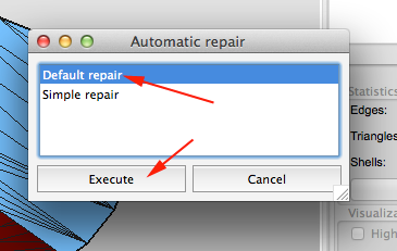
- Click automatic repair:
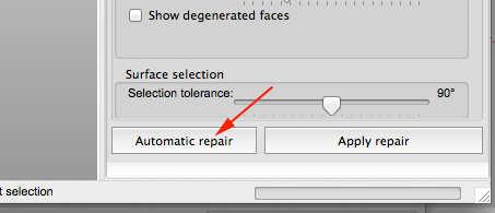
- Click Execute Default
Click on Apply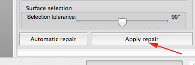
- Select Remove old part

- CTRL+Click on the part and export
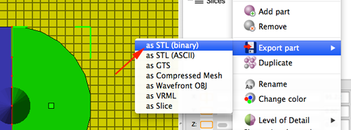
- Repeat for other side.
Low Poly
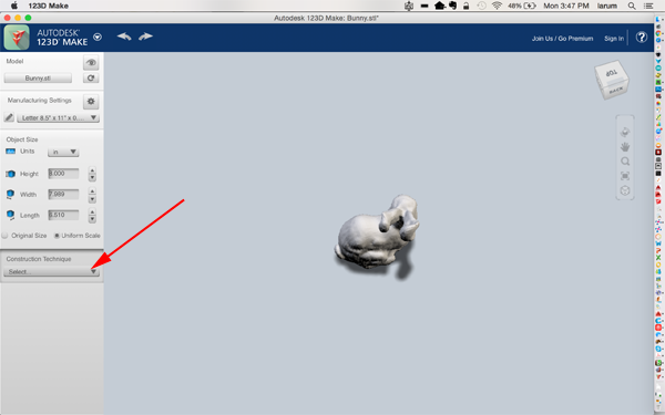
- Start with a solid 3D model like the Stanford Bunny.
- Open Autodesk 123D Make.
- Click on the import button in the upper left corner:

- Navigate to your model.
- Under Construction Techniques on the left hand side select Folded Panels:
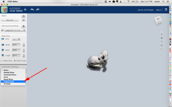
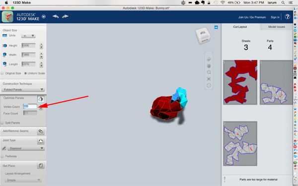
- Play around with the Vertex count:
- Click on the arrow in the top left corner and select Export Mesh from the options.

Low Poly with MeshMixer
Other Ideas
- Whistles
Science behind whistles - American Whistle Corp.
How a whistle works - Fidget Cube
- Fidget Star
- Coffin's Cube
- Knot Burr Puzzle
- Small box and lid
Nut and Bolt
- Launch AutoCAD.
- Create a new drawing. Select File>New Drawing:

- Select acad.dwt template file and press the Open button to continue to the drawing screen.

- Find the commandline.

If it is not present you should be able to open it it by selecting Window> Command Line
Other ways to display the command line are:
• Pressing Command+3 on Mac, CTRL+9 on Windows.
• Pressing F2
•Typing COMMANDLINE or CLI - You want to set your units to millimeters. Type UN and select UN (UNITS):

or select Format>Units from the top menu to bring up the Units Dialog box.
Set your units to millimeters: .
.
- You want to create a resolution appropriate for 3D printing. Type FACETRES and set it to 10.
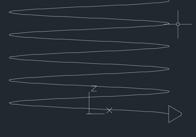
- Type HELIX and press RETURN.
Set the center point to 0,0,0
Set the bottom radius to 7
Set the top radius to 7
Set the height between turns to 2.
Set the height to 10. - Set the view to FRONT.
- Create a new UCS and set it to view.
- Draw this shape:

- Type PE for PEDIT and press RETURN.
Type M for multiple and press RETURN.
Select all the lines of the triangle shape and press RETURN twice.
Type J for Join and press RETURN until the commandline is clear. - Reset the view to WCS.
- Align the center of the base of triangle with the endpoint at the bottom of the helix:
- Type VSCURRENT and change the view to Shaded with Edges.
- Type SWEEP and press RETURN.
Select the triangle shape and press RETURN.
Click on the helix and press RETURN. - Type CYL for CYLINDER.
Specify center point of base at 0,0,-.75
Set the radius to 7
Set the height to 20 - Type UNION and click on the kelix and the cylinder.
- Rotate the view so that yo can see the top of the cylinder.
- Type CYL for CYLINDER.
Specify center at the center of the top of the cylinder.
Set the radius to 9
Set the height to 8 -
Type FILLETEDGE
Set the Radius to 2.0000
Select both edges and press RETURN twice. - Type POLYGON
Type 6 to change the number of sides
Set the center of the polygon to the top center of the cylinder you just created.
Type I for inscribed
Set the radius of the circle to 9 - Type EXTRUDEand press RETURN.
Click on the polygon and set the extrusion height to -8. - Type INTERSECT and press RETURN.
Select the cylinder and the extruded polygon. - Type CYL for CYLINDER.
Set the center point of base to 50,50,0
Set the base radius to 12
Set the height to 10 -
Type FILLETEDGE
Set the Radius to 2.0000
Select both edges and press RETURN twice. - Type POLYGON
Type 6 to change the number of sides
Set the center of the polygon to 50,50,10
Type I for inscribed
Set the radius of the circle to 12 - Type EXTRUDEand press RETURN.
Click on the polygon and set the extrusion height to -10. - Type INTERSECT and press RETURN.
Select the cylinder and the extruded polygon. - Type CO for COPY and press RETURN.
Select the cylinder with the swept helix.
Set the base point to 0,0,-.75
Set the second point to 50,50,0 and press RETURN - Type SCALE and press RETURN.
Set the base point to 50,50,0
Set the scale factor to 1.15 - Type SUBTRACT and press RETURN.
Select the outer shape and press RETURN.
Select the scaled up cylinder and press RETURN.
- Type EXPORT and press RETURN.
Name the file
Select solids or watertight meshes
Polyhedrons
The simplest way to create polyhedrons in AutoCAD is by using a script.- Download the Platonic polyhedra (3D) - tetrahedron, octahedron, icosahedron (LSP for AutoCAD, by Takaya Iwamoto) script.
- Launch AutoCAD
- Type APPLOAD and press RETURN.
- If you just want to use this script in this session click LOAD.
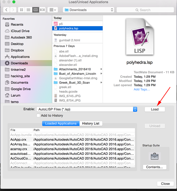
- If you want the script in your startup suite click on CONTENTS:
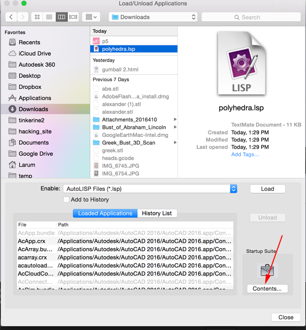
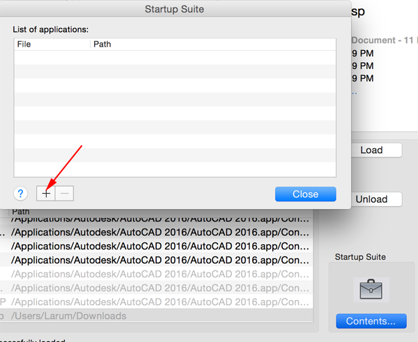
Then click on the add button:
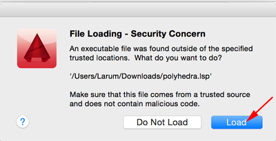
- Don't worry if you see this warning:
- To use the scripy type TETRA, OCTA or ICOSA.
Making your own Icosahedron
- Launch AutoCAD
- Create a new drawing. Select File>New Drawing:

- Select acad.dwt template file and press the Open button to continue to the drawing screen.

- Find the commandline.

If it is not present you should be able to open it it by selecting Window> Command Line
Other ways to display the command line are:
• Pressing Command+3 on Mac, CTRL+9 on Windows.
• Pressing F2
•Typing COMMANDLINE or CLI - You want to set your units to millimeters. Type UN and select UN (UNITS):

or select Format>Units from the top menu to bring up the Units Dialog box.
Set your units to millimeters: .
.
- You want to create a resolution appropriate for 3D printing. Type FACETRES and set it to 10.
- Type POLYGON and press RETURN.
Type 5 to create a pentagon and press RETURN.
Type E to create an edge and press RETURN.
Type 0,0,0 for the starting point of the edge and press RETURN.
Type 40,0 for the ending point of the edge and press RETURN.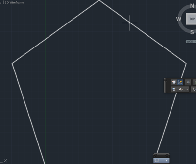
- Type Z and press RETURN.
Type E and press RETURN.
This will zoom into your drawing. - Type POLYGON and press RETURN.
Type 3 to create a triangle and press RETURN.
Type E to create an edge and press RETURN.
Type 40,0 for the starting point of the edge and press RETURN.
Type 0,0 for the ending point of the edge and press RETURN.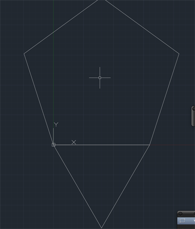
- Type POLYGON and press RETURN.
Type 3 to create a triangle and press RETURN.
Type E to create an edge and press RETURN.
Click on the top vertex and then on the vertex positioned at 40,0.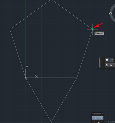
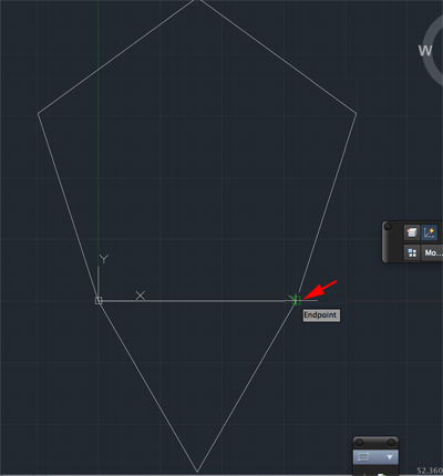
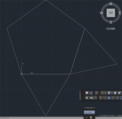
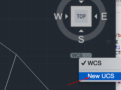
- Click on WCS and select New UCS.
- Click on the middle of the base of the first triangle then click on the opposite vertex point. Them type 0,0,100 and press RETURN.
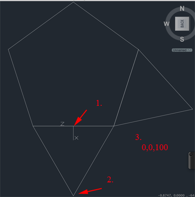
- Type C for circle and set the center at the middle of the base of the first triangle. Now click on the vertex opposite the base.
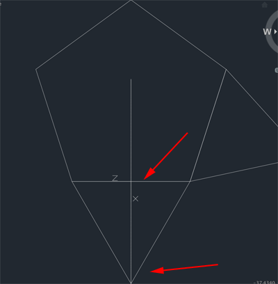
- Click on WCS and select New UCS.
- Click on the middle of the base of the second triangle then click on the opposite vertex point. Them type 0,0,100 and press RETURN.
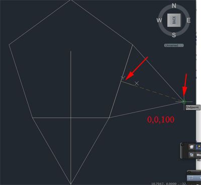
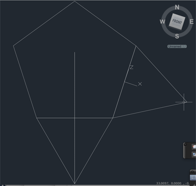
- Type C for circle and set the center at the middle of the base of the second triangle. Now click on the vertex opposite the base.
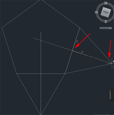
- Click on WCS and adjust your view:
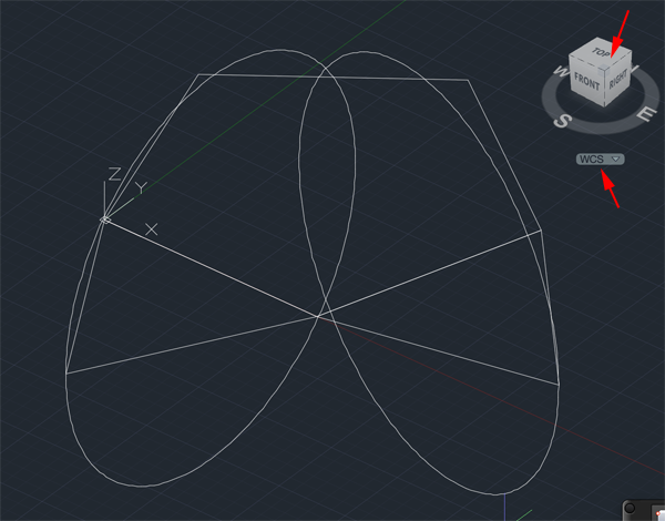
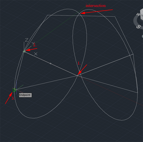
- Type ALIGN and press RETURN.
Click on the first triangle press RETURN.
Click in vertex 1 twice, click on vertix 2 twice. Click vertex 3 once and then click where the circles intersect:
- Type VSCURRENT and press RETURN.
Change to Shaded with Edges - Convert the triangle to a region:
- Delete the guide lines:
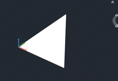
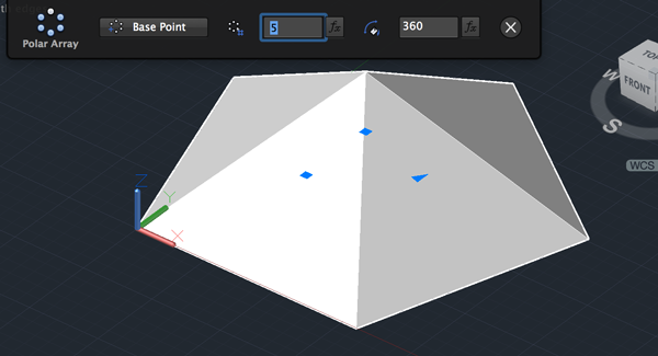
- Type ARRAY and press RETURN.
Click on triangle and press RETURN
Type Po for Polar and press RETURN.
Click on the top vertex to select rotation point.
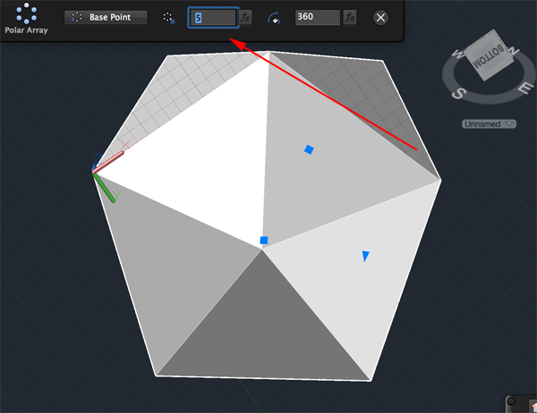
- Change the number to 5
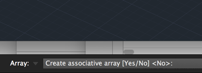
Type AS and change to No. This will allow you to edit the elements of the array and then press RETURN:
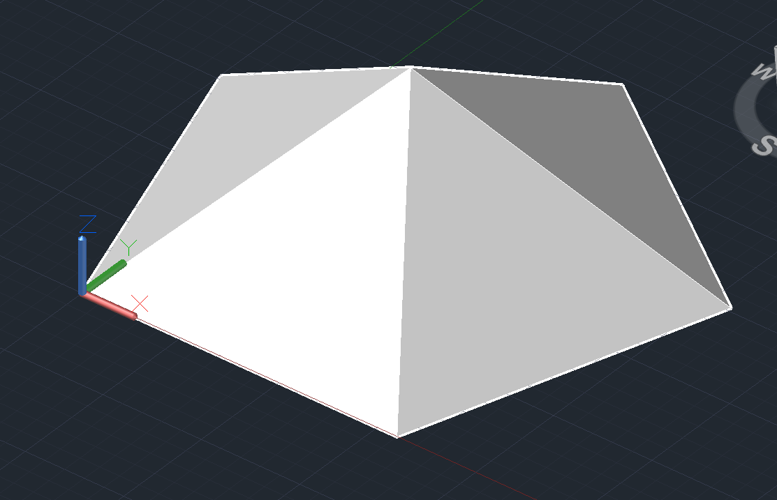
- Select and delete the original triangle and the triangle created in the array:
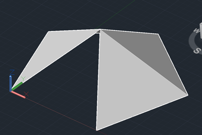
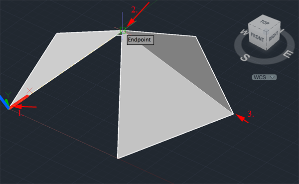
- Click on WCS and select New UCS.
- Click on vertex 1, then vertex 2 then vertex 3.
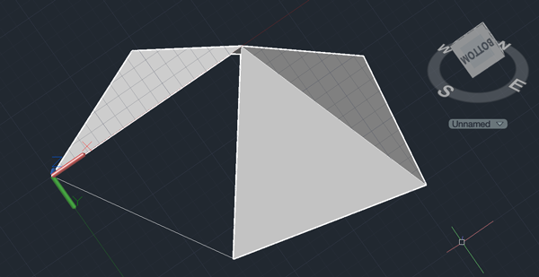
- Type ARRAY and press RETURN.
Click on the triangle to the right of the empty area and press RETURN/li> Type Po for Polar and press RETURN.
Click on the bottom vertex opposite vertex 3 . - Change the number to 5
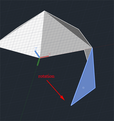
Press RETURN until you have created another 5 sided pyramid: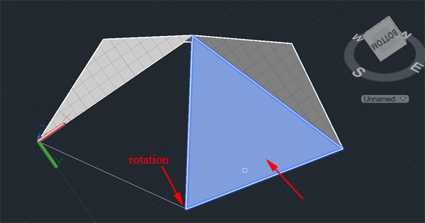
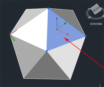
- Delete the extra trangle
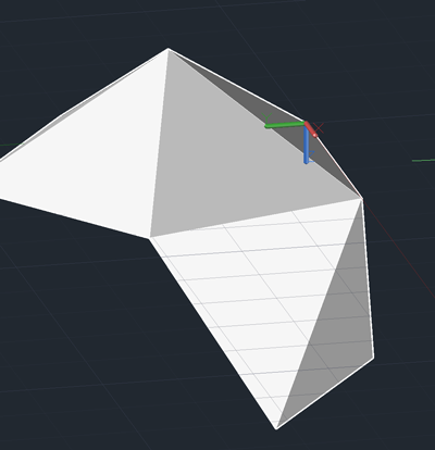
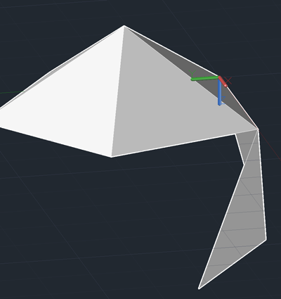
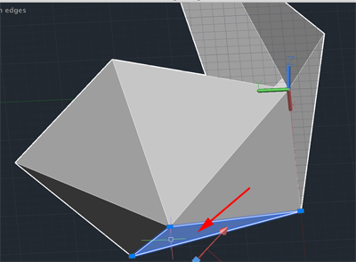
- Continue rotating, creating new USCs, generating ARRAYs and deleting the extra triangles.
You might have to delete some of your triangles in order to create a complete ICOSAHEDRON.

- Type CREATESOLID and press RETURN.
Select all of your triangles and press RETURN.
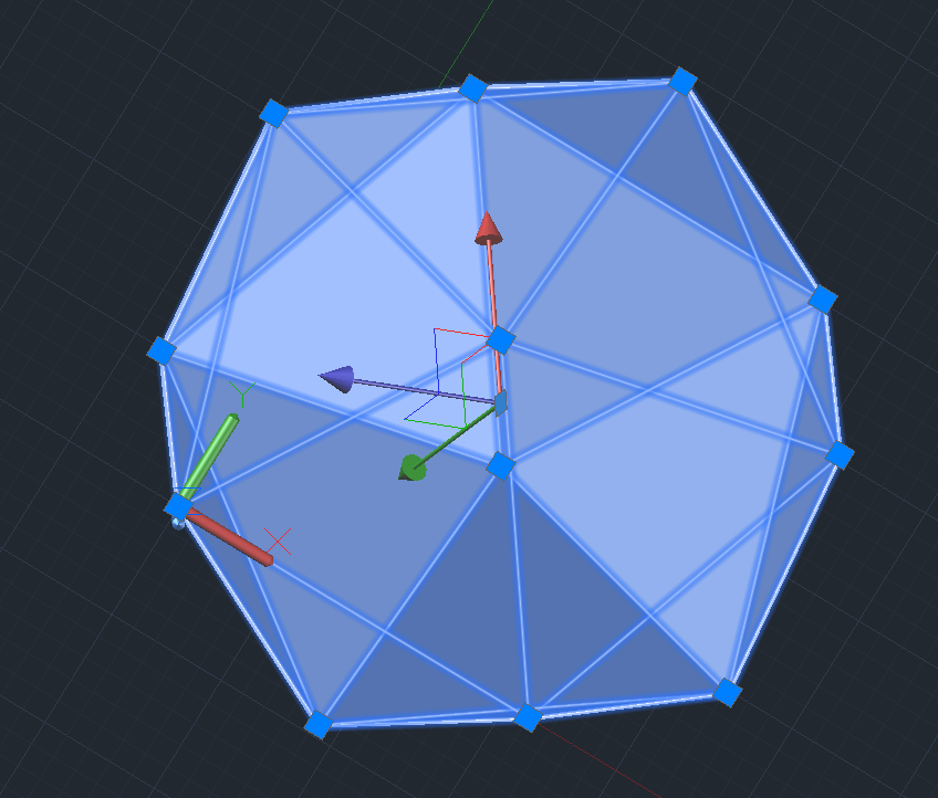
- Export your icosahedron.
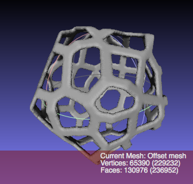
Tutorial derived from AutoCAD 2015 Icosahedron Tutorial by Pedro Martins-Mour&atile;o
