Flashing Lights
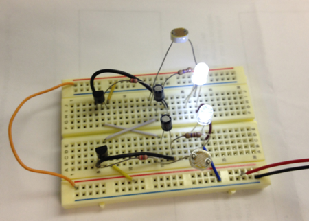
This is a 2 transistor astable multivibrator circuit. This particular version uses PNP transistors such as 2N3906, 2N4403, PN2907, or 2N2907.
The 470 ohm resistors determine the LED brightness. Lower resistance means higher current, and more light. LEDs that require more current or have a higher operating voltage (such as green and yellow) may work better with 300 ohms.
The RC time constant of the resistor and the 22uF capacitor determines the on time for each side. (The two sides do not need to match - you can vary the RC time constant for one side to get a lower or a higher duty cycle).

Schematic modified from Bill's Hobby Circuit Library
The 470 ohm resistors determine the LED brightness. Lower resistance means higher current, and more light. LEDs that require more current or have a higher operating voltage (such as green and yellow) may work better with 300 ohms.
The RC time constant of the resistor and the 22uF capacitor determines the on time for each side. (The two sides do not need to match - you can vary the RC time constant for one side to get a lower or a higher duty cycle).

Schematic modified from Bill's Hobby Circuit Library
Part List
- Breadboard—Jameco
- Wire—Jameco
- Battery Clip—Jameco
- 9 Volt Battery
- 2 LED—Jameco
- 2 LDRs—Jameco
- 2 1KΩ Resistors—Jameco
- 2 470Ω resistor—Jameco
- 2 22µF capacitorJameco
- 2 2N3906 PNP transistor—Jameco
- On/Off Switch—Jameco
- 1/2 Dual Mini Board with 213 Holes Protoboard—RadioShack
Instructions

Schematic modified from Bill's Hobby Circuit Library
- Breadboard the circuit first to test it.
- Connect your power buses:
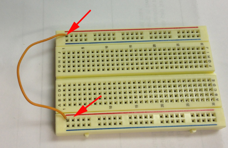
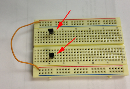
- Add your PNP transistors
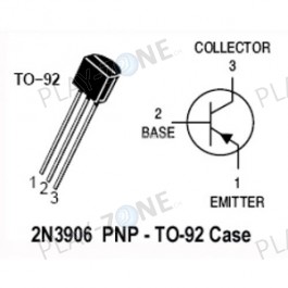 Image fromwww.play-zone.ch
- Add two wires. One from each transistor base. Criss cross the gutter:
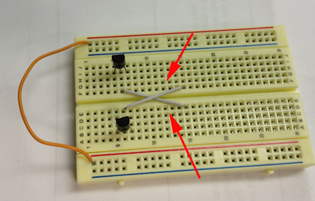
- Connect the crisscrossed wires to the short leads of our 22µF capacitors. Capacitors are polarized.
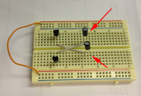
- Add the 470 Ω resistors from the long leads of your capacitors:
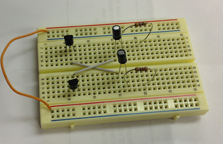
- Connect the anodes of the LEDS to the resistors:
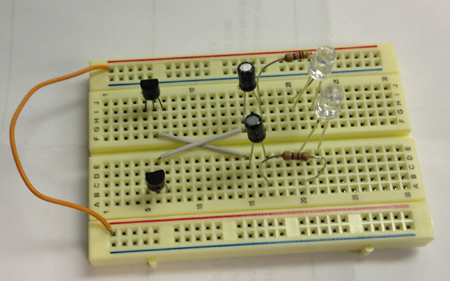
- Connect one lead of the LDRs to each of the LEDs' cathodes:
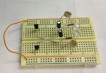
- Connect a 1K resistor to the other lead of the LDRs:
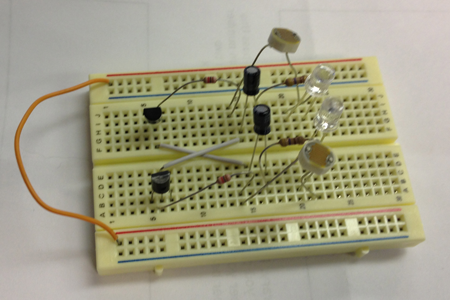
- Clip and strip two wires and connect the longer leads of the capacitors to the collectors of the transistors:
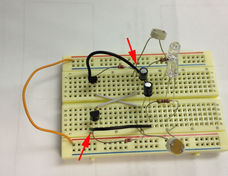
- Connect the emitters of the transistors to to Power:
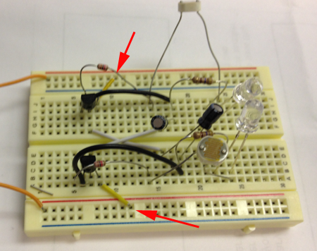
- Connect the cathodes of the LEDs together and connect them to GND
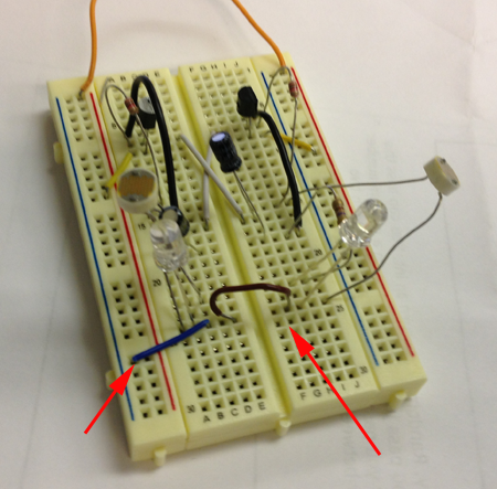
- Add your battery.
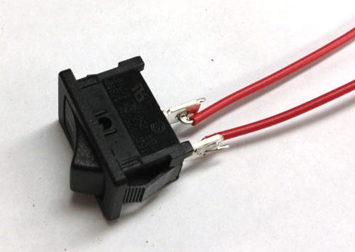
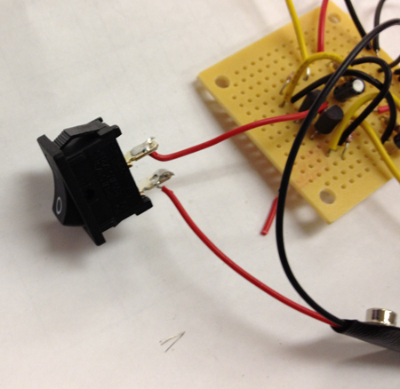
- Solder two wires onto your switch
- Solder two wires to the leads of the switch:
- Add the switch to your circuit.
- Connect your power buses:
- Freeform solder or use the protoboard to make your design more permanent.
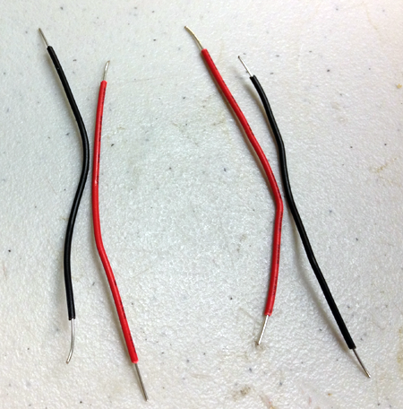
To use the Protoboard:- Cut and strip two pairs of black and red wires:
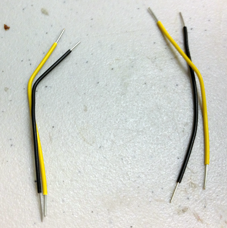
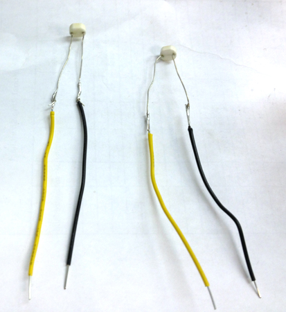
- Cut and strip two pairs of black and yellow (or some other color besides red or black) wires:
- Solder the red wires on to the anodes (the longer leads) of the the LEDs and the black wires on to the cathodes (shorter wires of the LEDs)
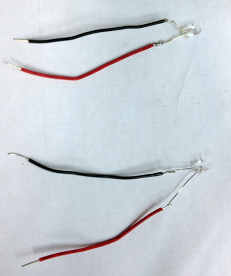
- Attach the LEDs to your board:
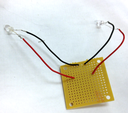
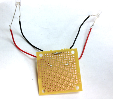
Here's the back:
- Solder a black and yellow wire to the leads of the LDRs. The LDRs are not polarized, so it doesn't matter which lead is attached to which wire:
- Attach the black leads of the LDRs to the black leads of the LEDs. The yellow wires should go somewhere else on the board:
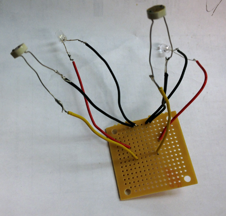
- Attach one side of the each 470Ω resistor to each red lead of the LEDs
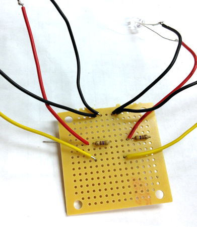
Here's the back:
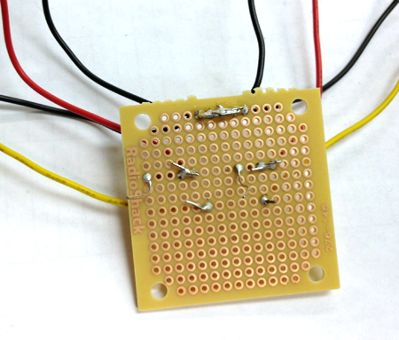
- Attach the other leads of the 470 Ω resistors to the positive (longer) leads of the electrolytic capacitors
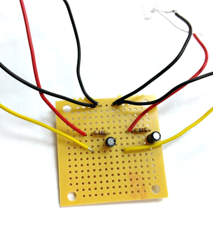
Here's the back
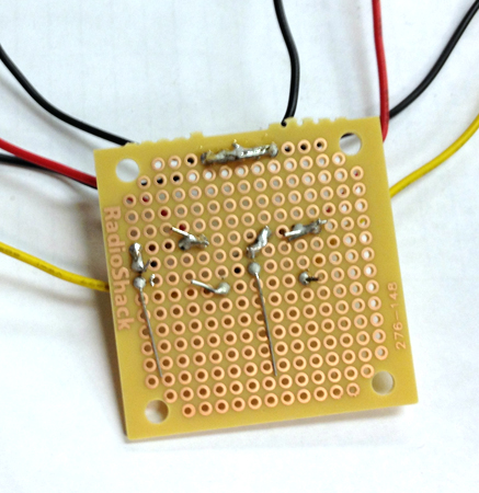
- Attach jumper wires between where the 470 Ω resistors meet the electrolytic capacitors and somewhere else on the board:
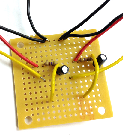
- Attach jumper wires between the negative terminals of the capacitor and one row up, same column as the other jumper wires:
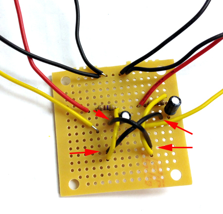
Here's the back:
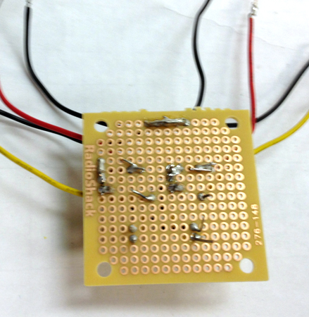
- Connect the black jumper wires to the yellow wires of the LDRs through the 1K Ω resistors. Remember that these wires cross (the left capacitor is connected to the right side and the right capacitor is connected to the left side):
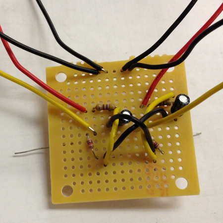
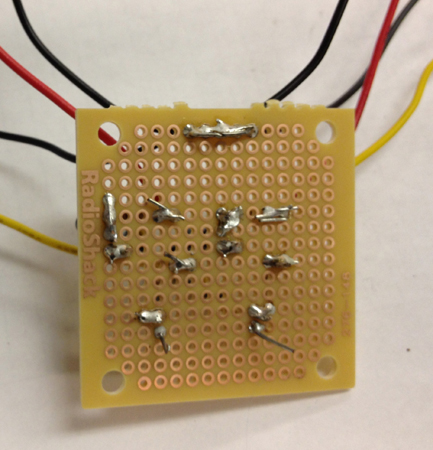
Here's the back:
- Add the transistor. Pay attention to orientation. The black jumpers and 1K &Omaega; resistors connect to the base. Also connect the yellow jumpers to the transistors:
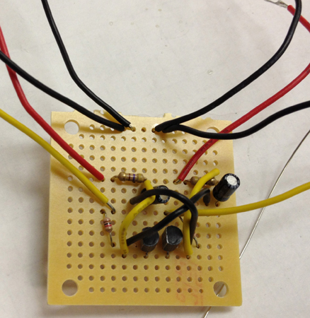
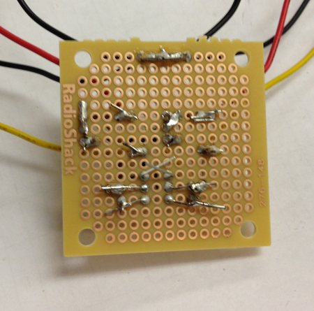
Here's the back:
- Connect the power wire of your battery supply to the transistor pin not attached to anything (the emitters) and the ground wire to the clump formed by the black wires of the LEDs and LDRs:
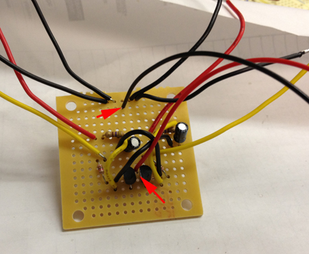
- Test the circuit by attaching a battery:
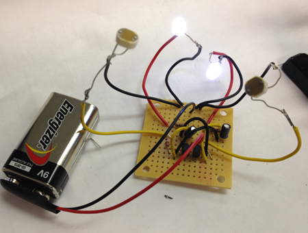
- If the circuit works, remove the battery:
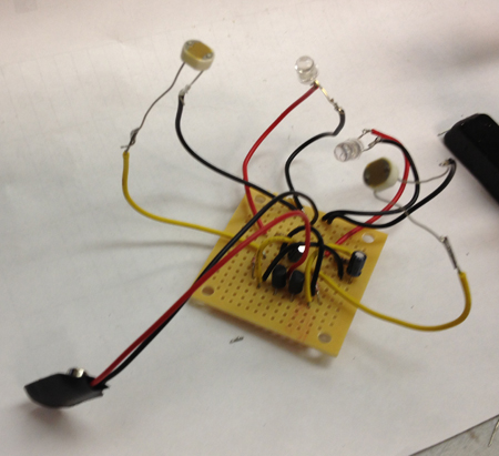
- Clip and strip the power line and solder both ends to the switch:
- Cover the back of the board with tape or other non-conductive material:
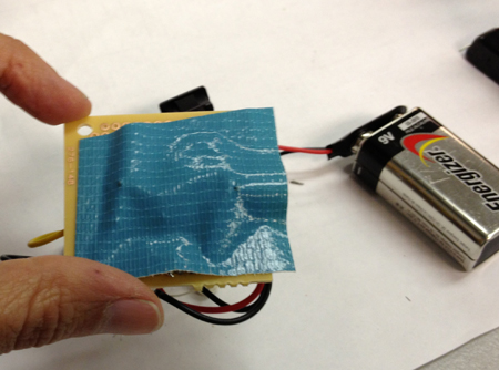
- Attach the battery, turn on and fold components into place:
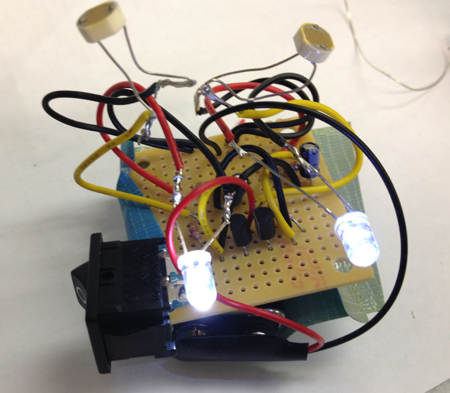
- Cut and strip two pairs of black and red wires:
- Use a digital caliper to measure your components. Write down the dimensions.
- Think about how people play instruments. Follow the steps of the design process, then design the housing that reflects your thought process.
Basic steps of the Design Process
The Design Process requires- Describe the general situation or problem you are trying to solve. Instead of asking what do you want to design? ask why do you want to design that? and what problem and or need will your design ultimately be solving?
- Identify your target audience, the group that will benefit from your project. Is the target population an individual, a group, a specific community, or a larger, identifiable population? Is the target population from a specific location (country, region, town), demographic (age or gender), or other identifying characteristics (health condition or employment)? Think about how is your target population connected?
-
Identify the requirements and constraints. A requirement is a need or a necessity; it's what a particular product or service should do. A constraint is a restriction on the degree of freedom you have in providing a solution to a need or problem.
- Ask what would make this fun to play with?
- Ask what compromises need to be made when you design?
- Determine if the compromises are absolutely necessary?
- Determine if your solution can be improved?
- By taking a new approach.
- By making the design more accurate.
- By making the design more safe.
- By making the design more convenient.
- By making the design easier to maintain.
- By making the design cheaper to produce.
- By making the design more attractive.
- Determine if you can reduce the costs by eliminating parts, using different materials, changing the way the product is manufactured?
In a nutshell
- Design Step 1: Identify the Need
- Design Step 2: Research the Problem
- Design Step 3: Brainstorm Possible Solutions
- Design Step 4: Engineering Analysis-select the most promising solution
- Design Step 5: Construct a Prototype
- Design Step 6: Evaluate/Manufacture a Final Product-Reiterate
Getting Started
Keep a notebook to keep track of your questions and answers. The design process will help inform your choices and should be an integral part of your creative process.-
Research existing solutions. What aspects of the design appeal to you, why?
- Research how people hold things, and how they play instruments. Make sure you know more about this problem than what is provided here on this web page.
- What are your constraints? Make a list.
- Observe how people make music, when, where, and with whom?
- Make sketches. Draw a top view, a side view, an isometric view and include dimensions. Your drawings are your blueprints. Someone else should be able to use your drawings to build an identical model.
