Toy Organ Design Challenge
The Challenge
Design the housing for a toy synthesizer.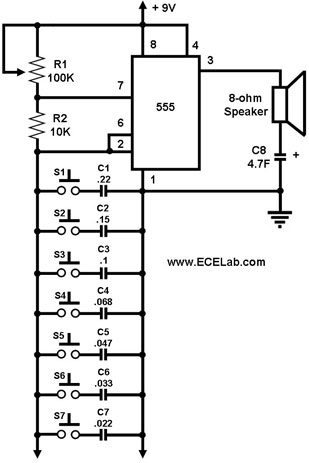
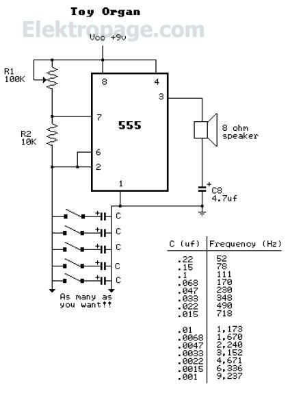
Schematics from www.ecelab.comcircuittoyorgan and www.elektropage.com
There are several variations of this circuit, but the parts list is derived from Forrest Mims's Toy Organ that appeared in Volume I: Timer, Op amp and Optoelectronic Circuits & Projects
Parts List
- Breadboard—Jameco
- Wire—Jameco
- 0.22µF Capacitor—Jameco
- 0.1µF Capacitor—Jameco
- 0.047µF Capacitor—Jameco
- 0.33µF Capacitor—Jameco
- 0.022µF Capacitor—Jameco
- 0.01µF Capacitor—Jameco
- 0.0047µF Capacitor—Jameco
- 0.0033µF Capacitor—Jameco
- 100µF Capacitor—Jameco
- 2 10KΩ Resistors—Jameco
- 5-10 Switch, PB, SPST—Jameco
- OFF-(ON) (Add this along the power line so that you can turn the organ on and off).—Jameco
- 1K Potentiometer—Jameco (This can get placed between C8 and and the speaker to control the volume)
- LDR—Jameco
- 555 Timers—Jameco
- 8 Pin IC Socket—Jameco
- 8 Ohm Speaker—Jameco
- Battery Clip—Jameco
- 9 Volt Battery
- Multipurpose PC Board with 417 Holes—RadioShack
Instructions
This is a fun circuit to play with as you can use a variety of capacitors and replace the potentiometer with an LDR.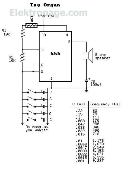
Modified from www.elektropage.com
- Breadboard the circuit first to test it.
-
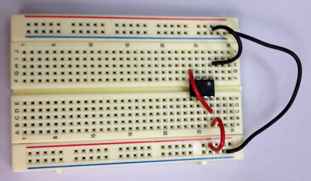
Connect GND to GND. Place chip in breadboard spanning the gutter and then connect power and (4,8) and GND (1) to the chip:
- Add your capacitors. Pick whatever values you would like based on the chart:

Chart from www.elektropage.com
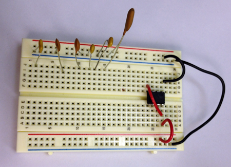
- Connect pin 3 of the 555 to the speaker:
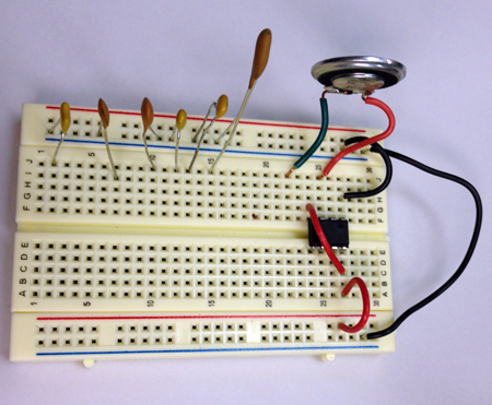
- Connect the ground side of the speaker to GND through a 100µF capacitor:
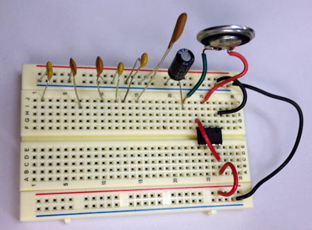
- Add a 10K resistor to pin 7:
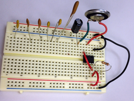
- Connect the other side of the 10K resistor to power through an LDR
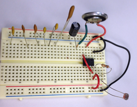
- Connect pin 2 to pin 6 and add another 10K resistor from pin 7:
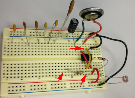
- Connect pin 6 to the other side of the resistor and add your first button:
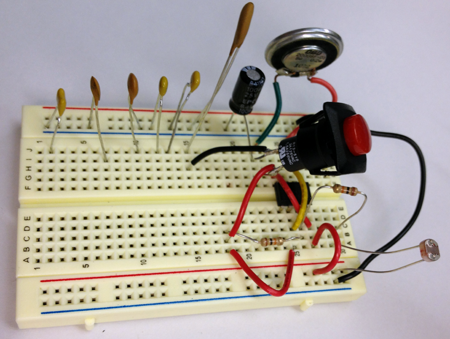
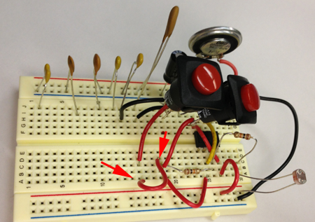
- Continue adding buttons to capacitors and connect each botton to the previous:
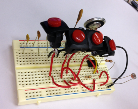
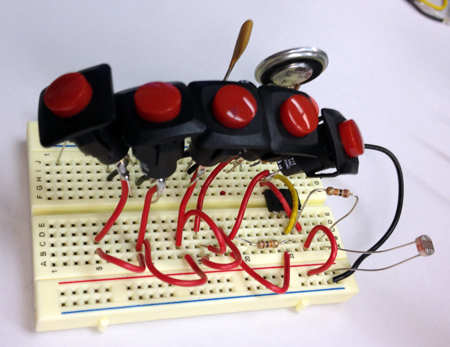
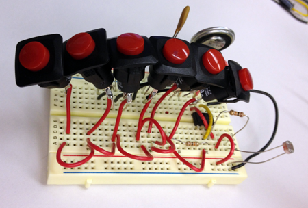
- Add a power supply:
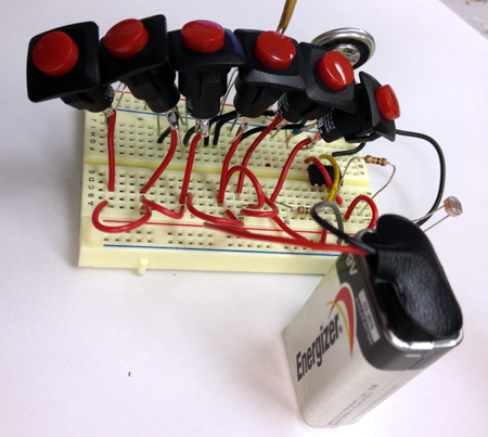
- Test the circuit:
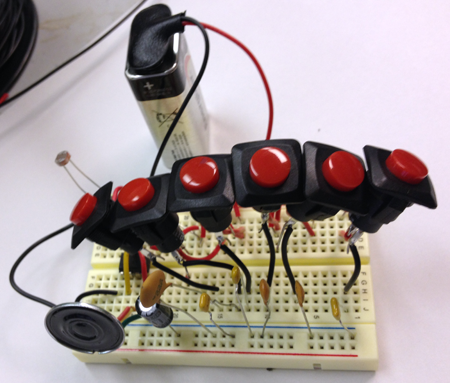
-
Connect GND to GND. Place chip in breadboard spanning the gutter and then connect power and (4,8) and GND (1) to the chip:
- Freeform solder or use the protoboard to make your design more permanent.
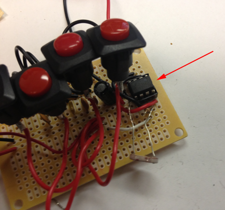
- Add the 8 Pin IC Socket:
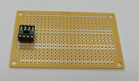
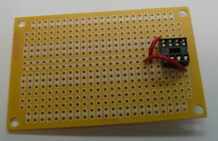
- Connect pins 4 and 8 to your power bus:
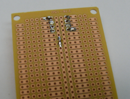
- Connect pin 1 to your GND bus:
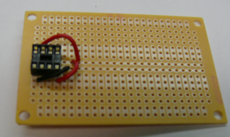
- Connect pins 2 and 6:
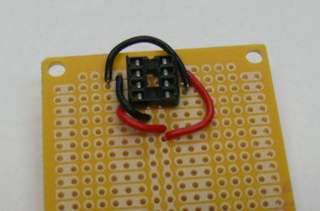
- Connect pin 7 to Power through an LDR:
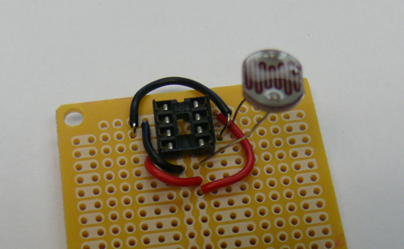
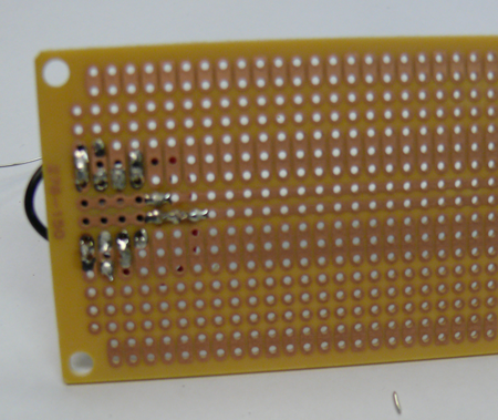
- Connect pin 3 to GND through the speaker and the 100µF capacitor. Connect the red lead to pin 3. Connect the black lead to the board where you can connect that line to GND through the capacitor:
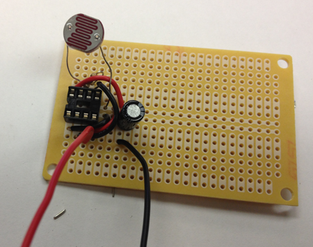
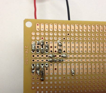
- Connect pins 6 and 7 through the resistor and connect 6 to the board through a wire:
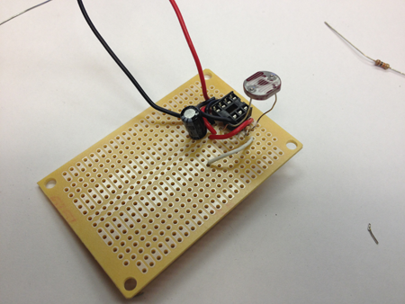
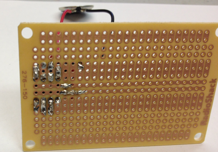
- Add the first button:
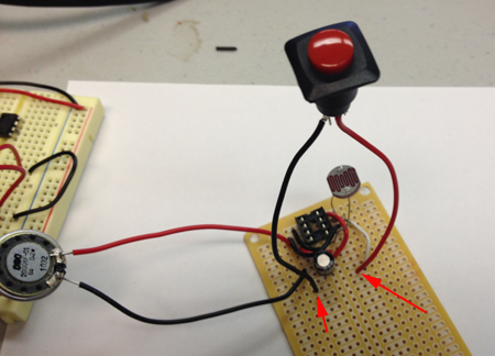
- Connect the button to GND through a capacitor:
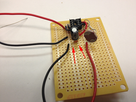
- Notice that you can bridge lines with solder:
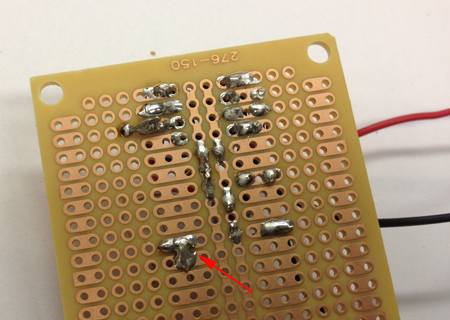
- Add the second button and capacitor:
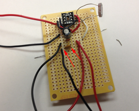
- Add your third button:
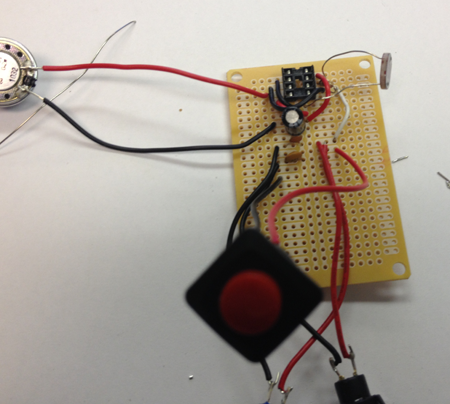
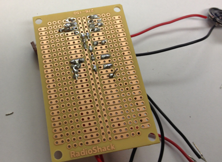
- Add the capacitor:
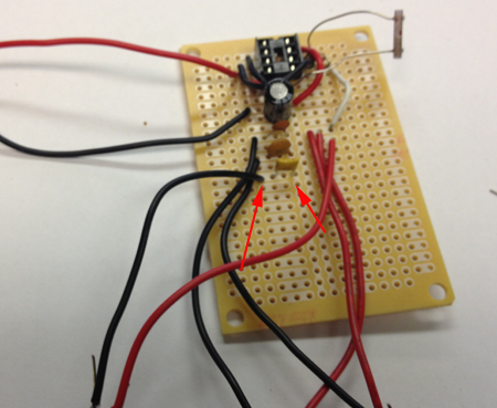
- Add the fourth button:
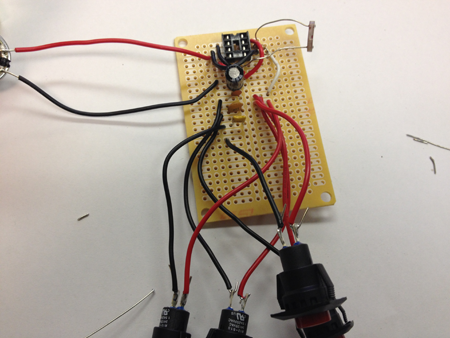
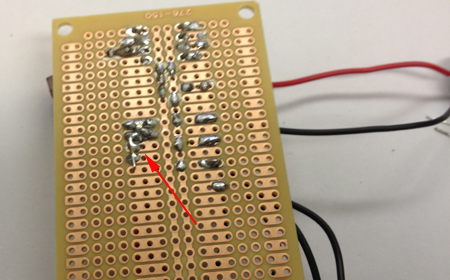
- Add the next capacitor:
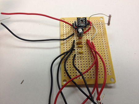
- Add the fifth button and the capacitor:
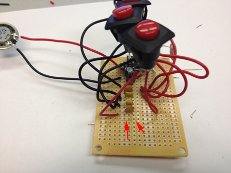
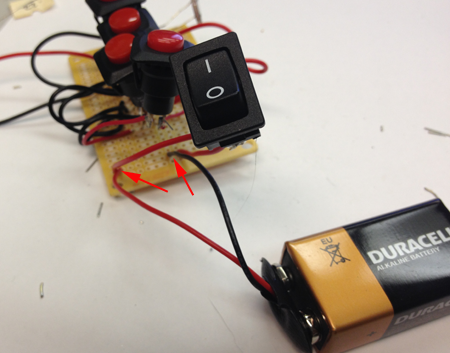
- Add your switch:
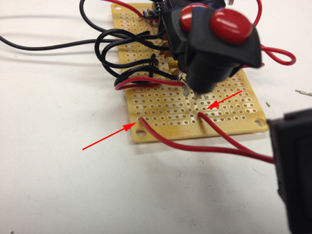
- Add your battery:
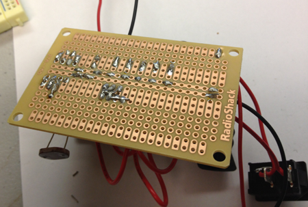
- Add the chip to the socket:
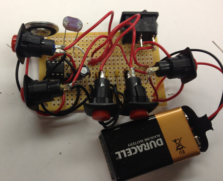
- Test and bend into shape:
- Add the 8 Pin IC Socket:
- Use a digital caliper to measure your components. Write down the dimensions.
- Research how people play with buttons and synthesizers. Follow the steps of the design process, then design the housing that reflects your research.
Basic steps of the Design Process
The Design Process requires- Describe the general situation or problem you are trying to solve. Instead of asking what do you want to design? ask why do you want to design that? and what problem and or need will your design ultimately be solving?
- Identify your target audience, the group that will benefit from your project. Is the target population an individual, a group, a specific community, or a larger, identifiable population? Is the target population from a specific location (country, region, town), demographic (age or gender), or other identifying characteristics (health condition or employment)? Think about how is your target population connected?
-
Identify the requirements and constraints. A requirement is a need or a necessity; it's what a particular product or service should do. A constraint is a restriction on the degree of freedom you have in providing a solution to a need or problem.
- Ask what are the disadvantages of the present solution to the problem?
- Ask what compromises have been made in the present solution?
- Determine if the compromises are necessary?
- Determine if the solution can be improved?
- By taking a new approach.
- By making the design more accurate.
- By making the design more safe.
- By making the design more convenient.
- By making the design easier to maintain.
- By making the design cheaper to produce.
- By making the design more attractive.
- Determine if you can reduce the costs by eliminating parts, using different materials, changing the way the product is manufactured?
In a nutshell
- Design Step 1: Identify the Need
- Design Step 2: Research the Problem
- Design Step 3: Brainstorm Possible Solutions
- Design Step 4: Engineering Analysis-select the most promising solution
- Design Step 5: Construct a Prototype
- Design Step 6: Evaluate/Manufacture a Final Product-Reiterate
Getting Started
Keep a notebook to keep track of your questions and answers. The design process will help inform your choices and should be an integral part of your creative process.-
Research existing solutions. What aspects of the design appeal to you, why?
- Research what people snack on and when. Make sure you know more about this problem than what is provided here on this web page.
- What are your constraints? Make a list.
- Observe how people approach devices with knobs and buttons and how they hold objects. Will your organ rest on a table, be worn, be held in a hand or be fixed to a surface?
- Make sketches. See Examples
Reading
The Psychology Of Everyday Things by Donald A. NormanSome other designs
![IMG_3340[1].JPG](../../../../images/circuits/toy_organ/IMG_3340%5B1%5D.JPG)
Image from
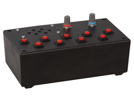
Image from Jameco
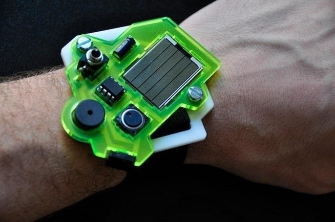
Image from WonderHowTo
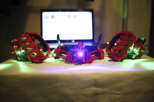
Image from www.winextra.com
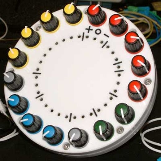
Image from www.dvice.com
