Introduction
Wang Jianwei, a Beijing-based Chinese artist, is having his first solo museum exhibition in North America at the Guggenheim Museum in New York City. Time Temple is an immersive exhibition of new work.Time Temple exemplifies Wong's perspective that art making is a continuous "rehersal" and the work explores how individuals think of and experience time. Each of the three components of the exhibit: an installation, a film and a performance, focuses on ambiguity, possibilities, time, movement, process, iteration, and metamorphosis.
Using 3D modeling and printing to explore Wong Jianwei's work makes sense. While 3D modeling and printing do not mimick Wong's process for creating his sculptures, 3DX incorporates many of the artist's central concerns including exploring possibilities, creating iterations and incorporatig change. 3DX allows an artist to create a series of work that documents in the work itself the process involved, the possibilities available and moments in time.
The Workshop
-
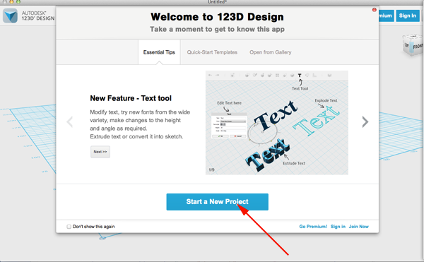
Open Autodesk 123D Design and start a new project:
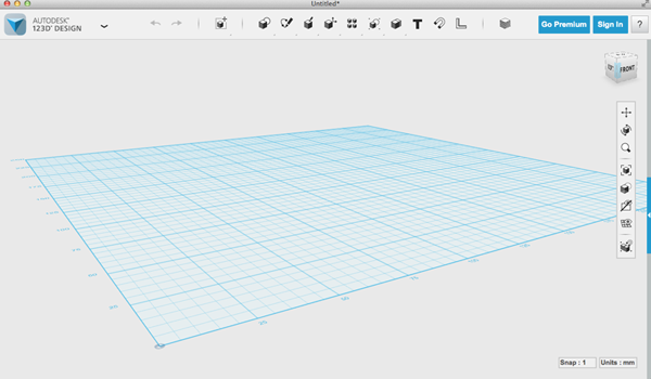
- Prepare the form (6 minutes):
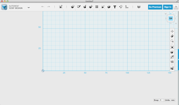
- Use the view cube in the upper right hand corner to change the view to Top:
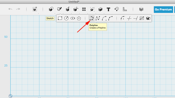
- Click on the Sketch menu to reveal the options:
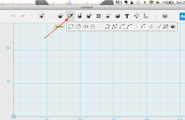
- Select Polyline:
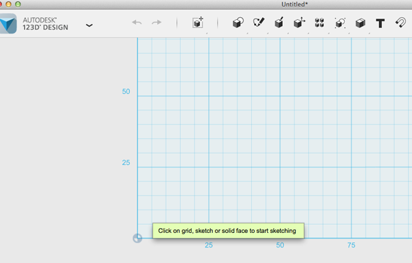
- Click on grid to select drawing plane:
- Click, move, click to create a shape within 25 x 50 millimeters:
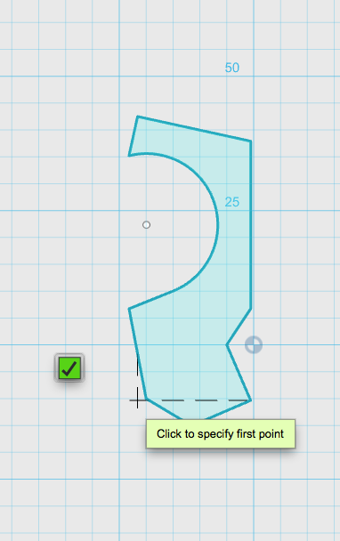
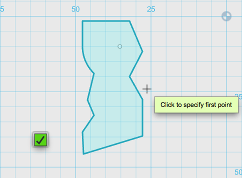
- When your shape is complete press Escape:
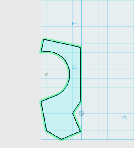
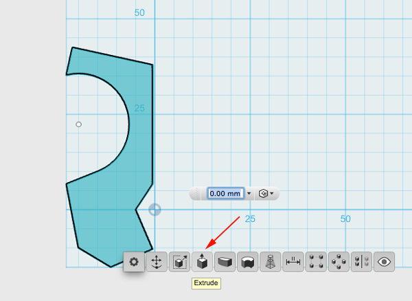
- Click on the shape. Then click on the widget. Select the Extrude option:
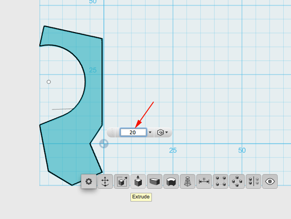
- Extrude by 20 millimeters:
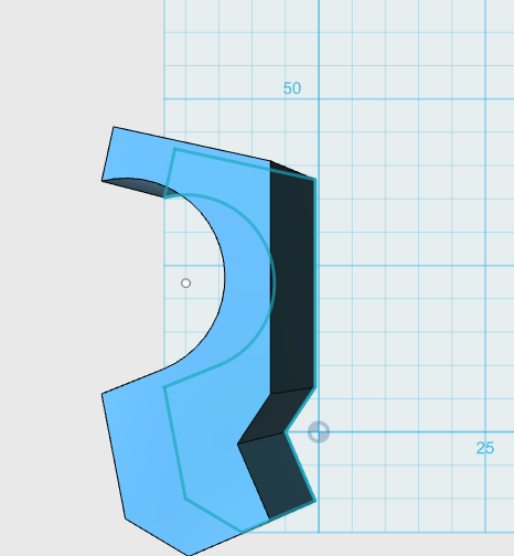
- Use the view cube to change the view:
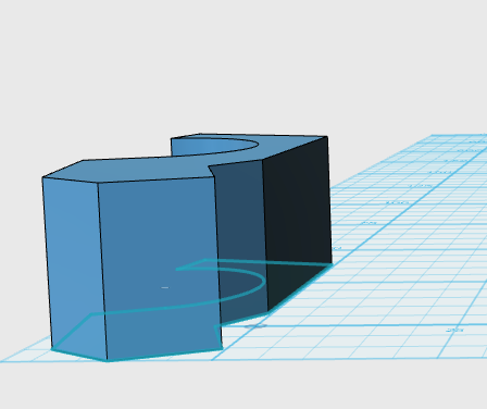
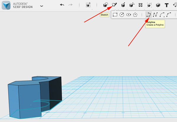
- Select Polyline again from the Sketch menu:
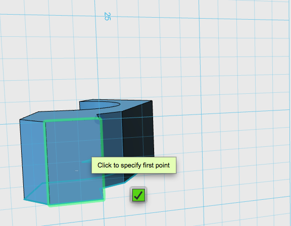
- Click on a face to select the drawing plane:
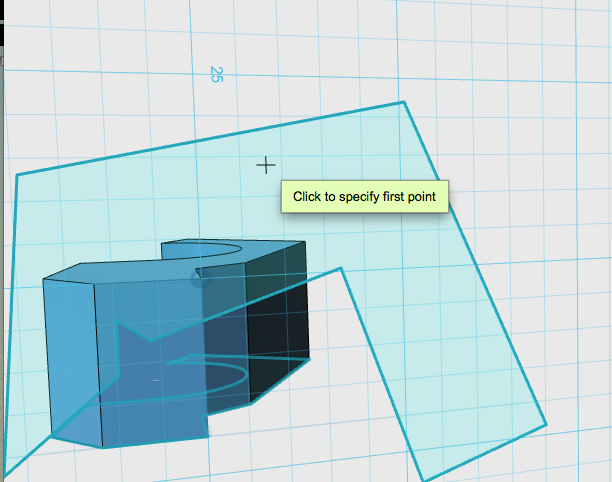
- Draw a shape at the top of your face. The interior angles of the shape will create slanted sides on your form if you want a less rectangular form:
- Click Escape to complete the shape:
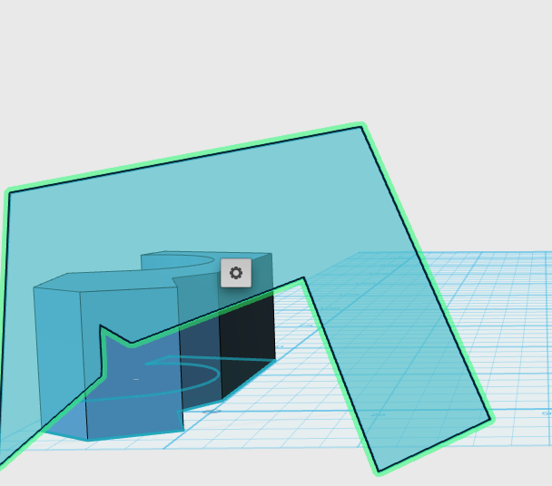
- Click on the shape, then click on the widget and select the Extrude option:
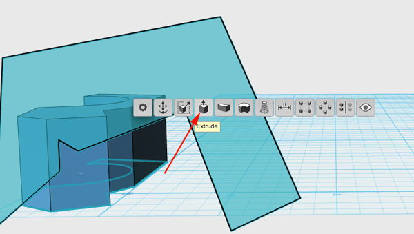
- Extrude so that you extrude the length of your form. This shape may need to be tweaked before extruding. If you don't like your results, then click on a vertex and move it to a better position. Click on the shape and widget again and extrude:
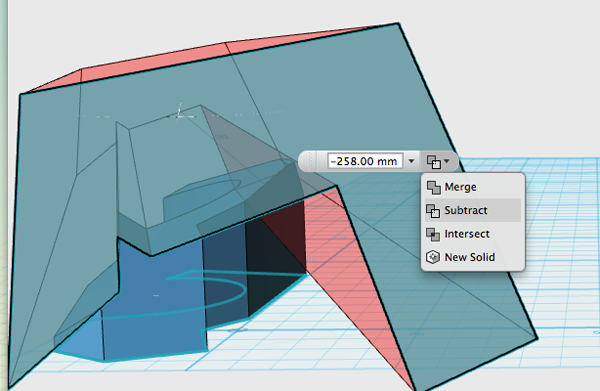
- Change to another view:
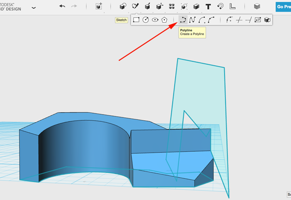
- Create another shape with the Polyline tool:
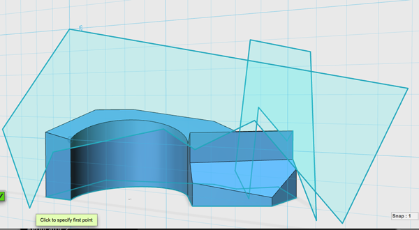
- Click on shape, widget, extrude, check the extrusion, adjust if necessary and extrude:
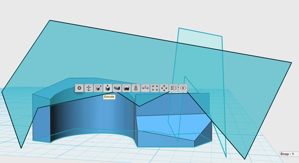
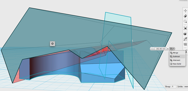
- Hide the sketches:
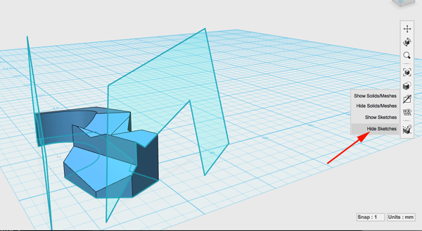
- Select Materials and select Oak
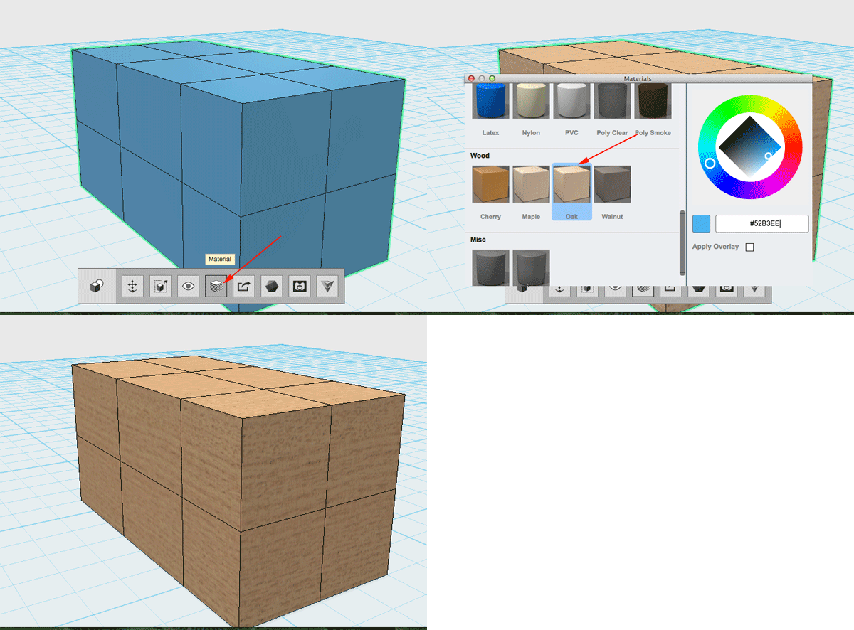
- Click on the file menu:
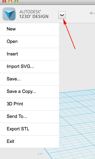
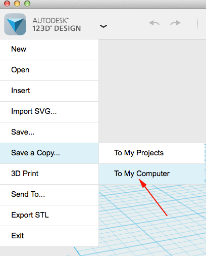
- Select Save a Copy to To My Computer
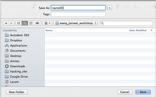
- Find the Wong_Jiangwei_workshop folder on the desktop. Select that and save your file with your name followed by two zeros:
- Use the view cube in the upper right hand corner to change the view to Top:
- Each round (3 minutes)
- Make four changes. At least one change must be a chamfered edge:
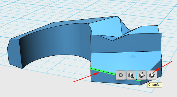
For the other three options you can select a vertex or an edge. You can tweak the vertices and edges or chamfer more edges: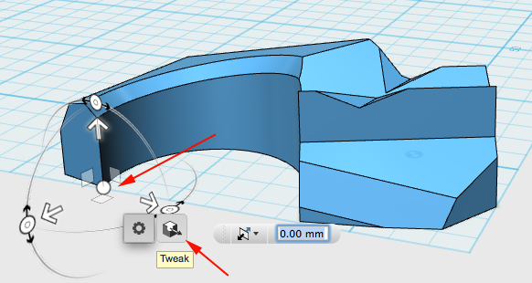
The first few rounds might call for drastic changes, the last rounds will be more about refinement. - After you have made your four changes click on the file menu:

- Select Save a Copy to To My Computer

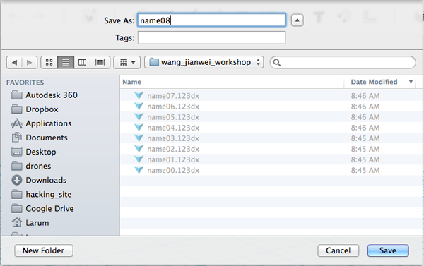
- Find the Wong_Jiangwei_workshop folder on the desktop (you should already be in it). Save the file with the name of the the original designer followed by the round:
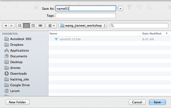
- Make four changes. At least one change must be a chamfered edge:
- Repeat moving stations and tweaking forms until you are back at the station you started at.
- Final Iteration (6 minutes)
- Make all your adjustments.
- You can add a detail by selecting a plane, drawing an polyline and making a slight extrusion:
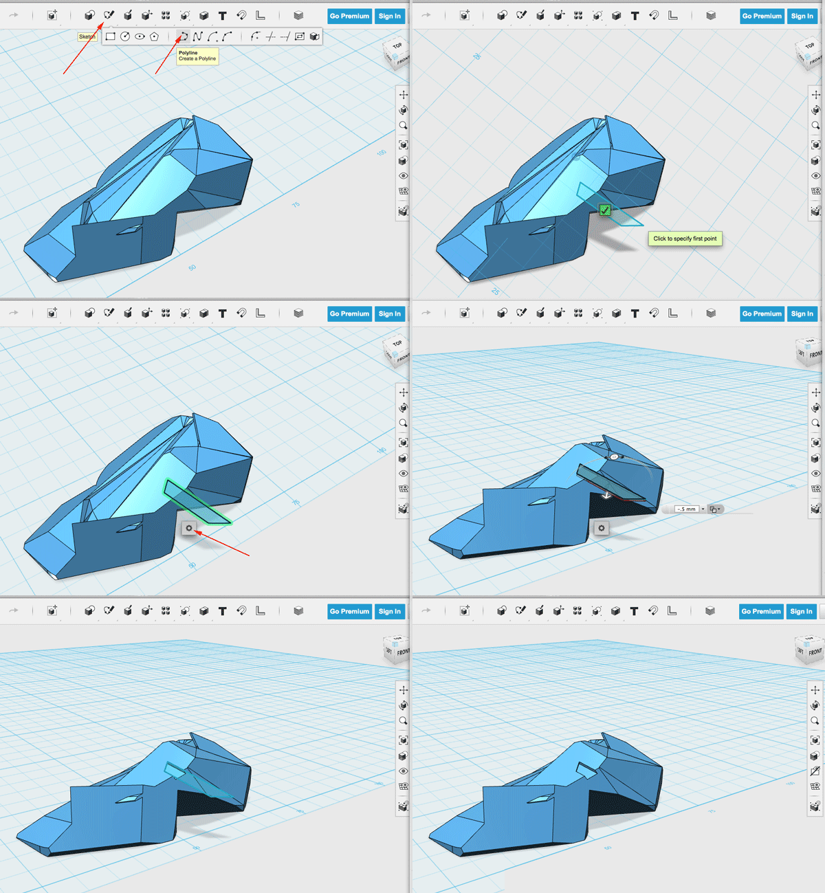
- Select Save a Copy to To My Computer
- From the File menu select Export STL

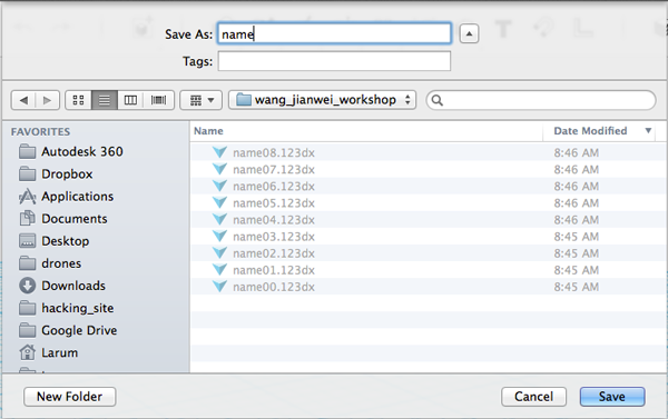
- Save the stl file with your name
Preparing the Models
The objective of this exercise is to create forms that can be pushed and pulled in ways that change the form, capture or deflect light and when printed and installed in a site-specific location effect how the space is perceived. Pushing and pulling faces and vertices calls for a mesh model. There are many applications that allow one to manipulate a mesh model, but some of these options require skills that many beginners to 3D modeling do not possess. When selecting an appropriate application one must consider the constraints and the goals. The selection may not be the best application for the task, but it may satisfy the constraints of limited time, funds, and experience. This is how 123D Design was selected for this activity. While this application can crash, it allows one to tweak edges or vertices, apply chamfers and fillets and perform boolean differences and is appropriate for novices after a model has been prepared.The constraints that we are working with is
- Time: a two hour workshop
- Accessibility: we wanted to limit ourselves to free software so participants, if they so choose could continue to work on project outside of workshop
- Content and Purpose: we decided that we did not need to start with exact replicas of the artist works, but that participants could start to create similar forms.
- Printer capabilities:It is faster to print a horizontal model than a vertical model due to how a 3D printer works: Therefore every model must have one flat side.
- Experience: participants may or may not have any experience with 3DX
Preparing the Model
While some programs allow you to select a face and then subdivide it, 123D Design does not. It does however allow you to sketch on a face and use those sketches as splitting entities.- Open 123D Design
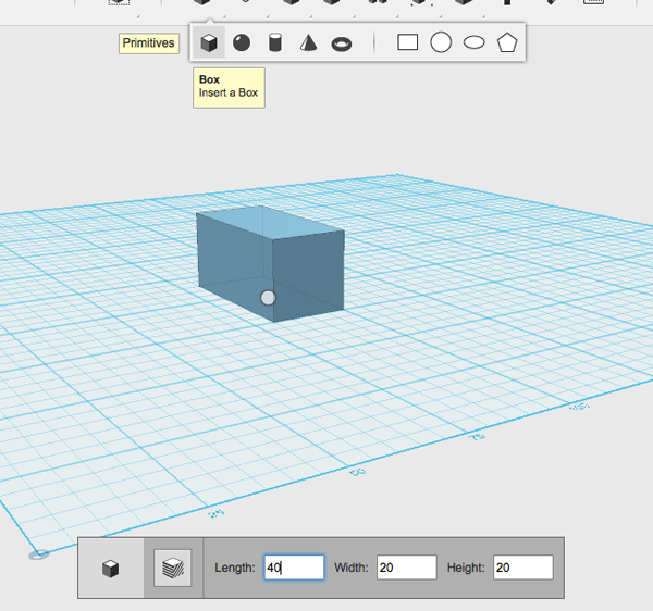
- Drag a box out and set the dimensions to 40x20x20:
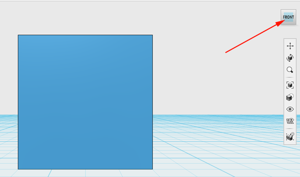
- Set the view to FRONT:
- Select Sketch Rectangle:
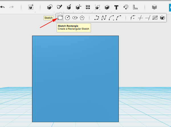
- Click on the FRONT face:
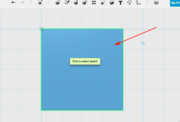
- Create 4 rectangles of equal size on the face:
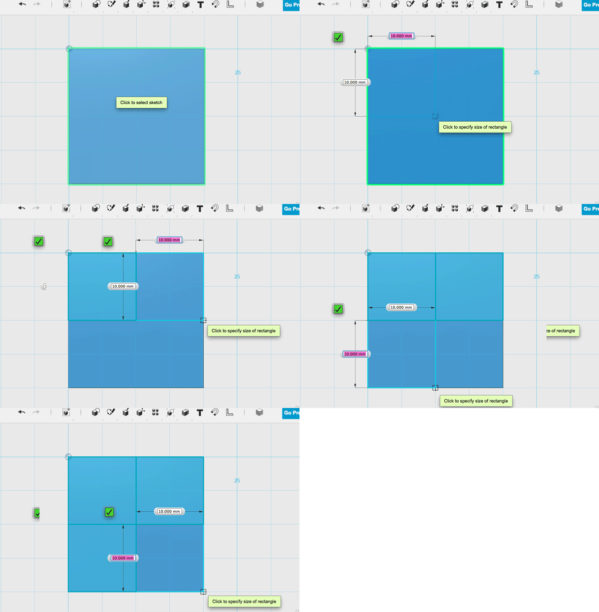
- Press ESC.
- Set the view to LEFT.
- Select Sketch Rectangle.
- Click on the LEFT face.
- Draw rectangles (these will not all be equal):
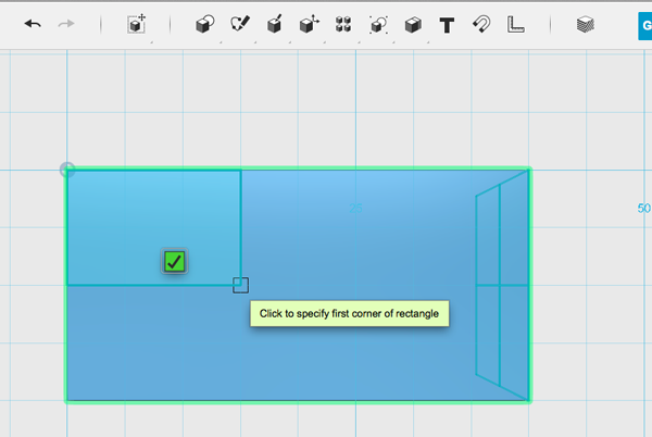
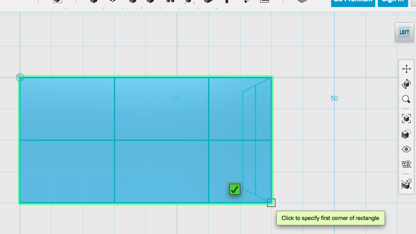
- Press ESC.
- Set the view to TOP.
- Select Sketch Rectangle.
- Click on the TOP face.
- Draw rectangles:
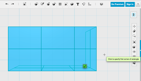
- Press ESC.
- Set the view to LEFT.
- Select split faces:
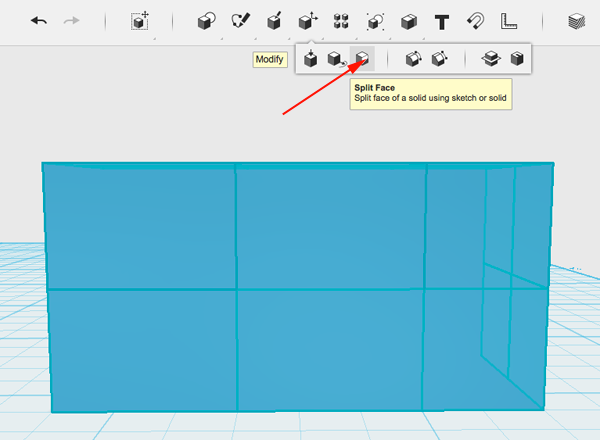
- Select the face:
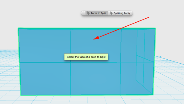
- Select splitting entity
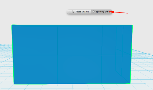
- Select the entity:
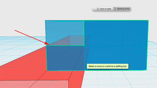
- Press RETURN.
- Repeat until original face is completely split.
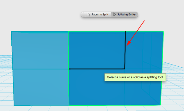
- You can toggle the sketches to see your progress:
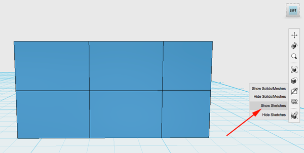
- After LEFT, FRONT and TOP views have been split, navigate to the RIGHT view.
- Select split faces.
- Select the RIGHT face.
- Select the splitting entity button and then the entity( you will be selecting the entity that was drawn on the opposite side)
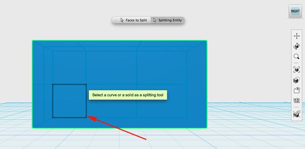
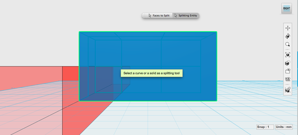
- Press RETURN.
- Continue with BACK and BOTTOM faces.
- Hide Sketches:
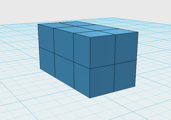
- Click on model and select Material

- Save the model.
- Rotate the model by 90° and save as a vertical version.
The Process
- There will be 6-8 named computer stations.
- There will be a foam core model of an empty room.
- Each station will have 123D Design opened and will display the model that groups will work on. The model may or may not be a modification of the one created in the previous step (Preparing the Models).
- There will be a 10 minute instruction period that will demonstrate the techniques outlined below.
- Each group will start by saving the model on their computer as station_name_1_group_name
- Each group will have 12 minutes to work on the model at their station. Number of moves will be limited. Number of subtractions will be limited. Each group should try to modify the form to bring out an idea. Does the model look like a figure, a lion, a bus, a river?
- At the end of 12 minutes, the models should be saved to the computer and exported as an STL file.
- Workshop coordinators will collect the 123D and STL files and begin the printing process.
- Groups will switch stations and start by saving the model. Since this is the first rotation, the model will be saved as station_name_2_group_name
- Groups will work for 10 minutes, save, export and then switch stations.
- There will be 4 rotations, printing will occur as models are completed. Models, once printed can be enhanced with color tape.
- Models from each round will be arranged in the model room and photographed.
- Another installation will be of how each model has changed over time. Each iteration of the model from a particular station will be arranged in the model room and photographed.
- Open 123D Design.
- Open either your horizontal or vertical model.
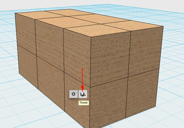
- Select a vertex
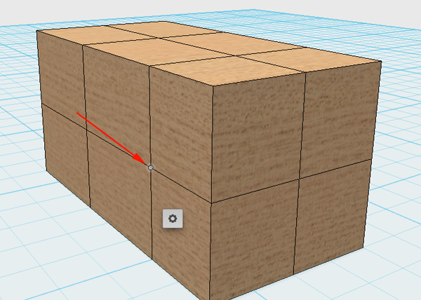
- Click on the widget and select Tweak:
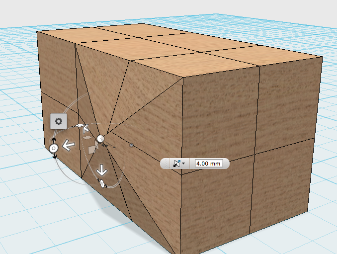
- Pull or push (try to avoid invalid moves and rotations which might crash the program). Consider saving frequently:
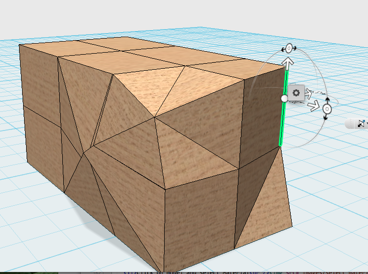
- You can also tweak edges. Select an edge:
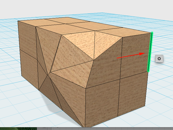
- Click on widget and select Tweak
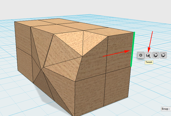
- Move the edge
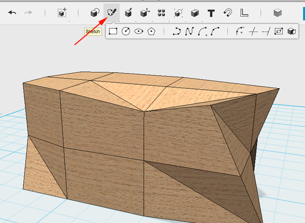
- Click on Sketch
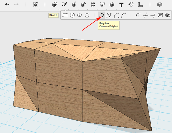
- Select Polyline
- Select a face to sketch on
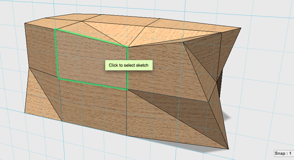
- Draw a line
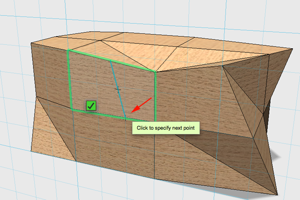
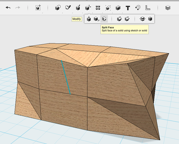
- Select Split face
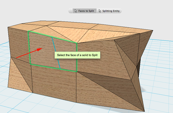
- Select the face
- Select the splitting entity button
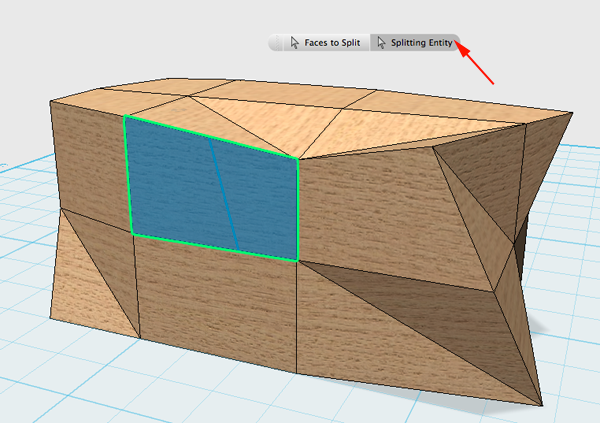
- Roll over the entity to highlight it
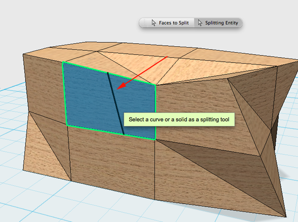
- Click to select and press RETURN
- Click on the line and then press DELETE
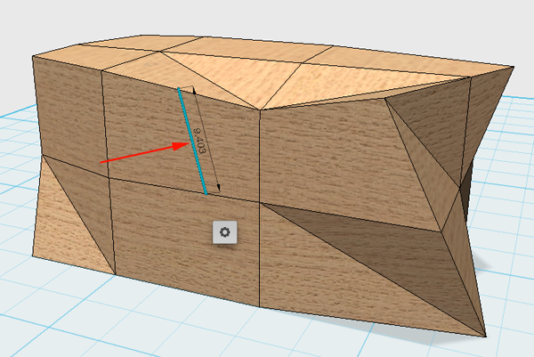
- Tweak the new vertex
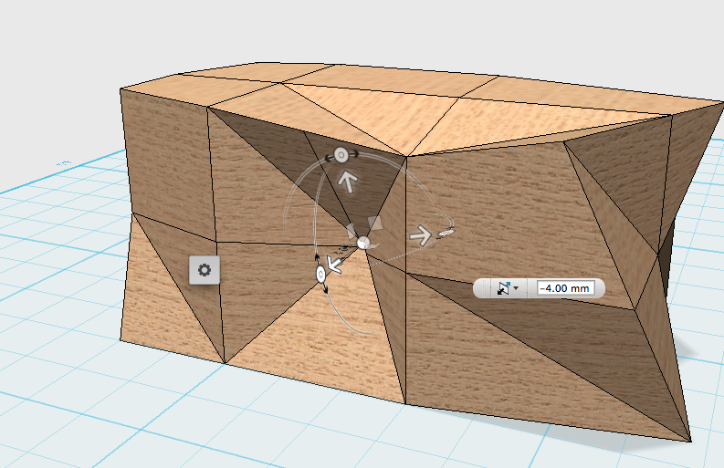
- Click on Sketch.
- Select Polyline.
- Select a face and draw a closed shape using an existing edge
- Select Split face
- Select the face then click on the Splitting Entity button:
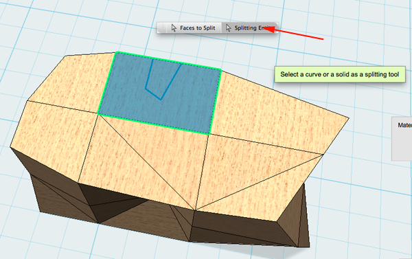
- Rollover the entity to highlight it:
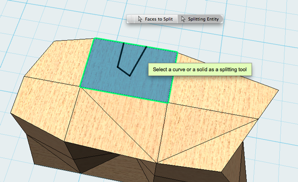
- Click to select and press RETURN:
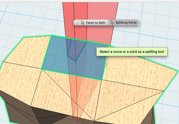
- Click on the face of the shape and then click on the widget:
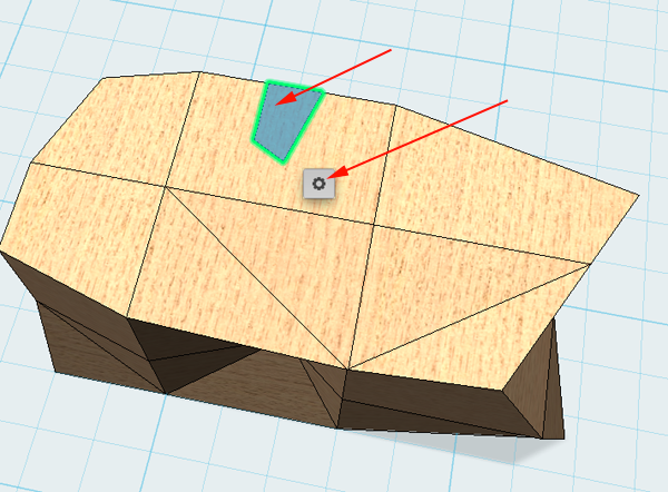
- Select PressPull:
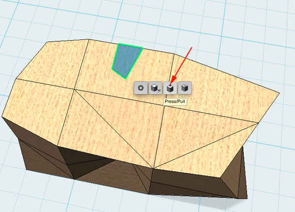
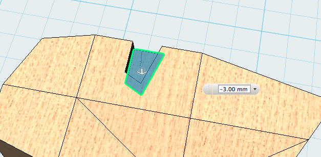
- Push the shape down and press RETURN:
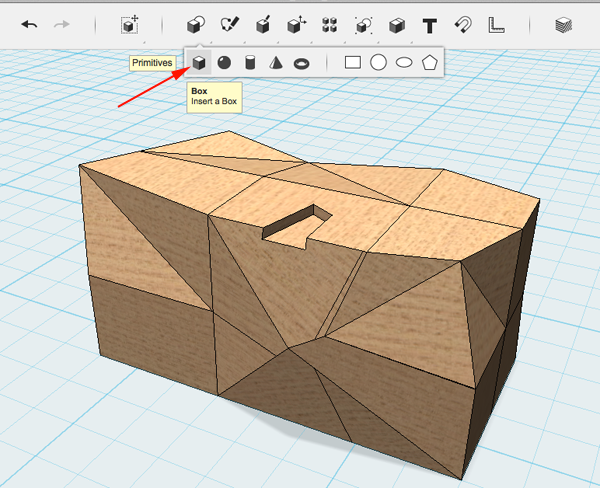
- Drag a box out:
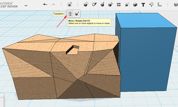
- Move the box close to the model and then click on the Transform tool:
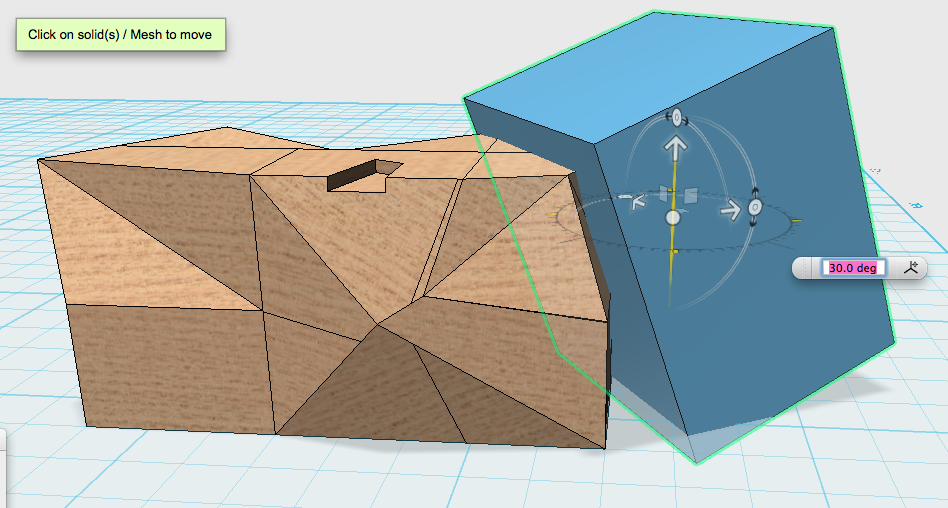
- Adjust the box so that it will create a clean cut:
- Select Subtract:
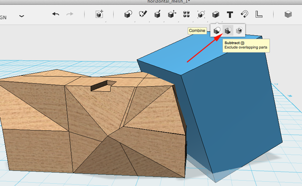
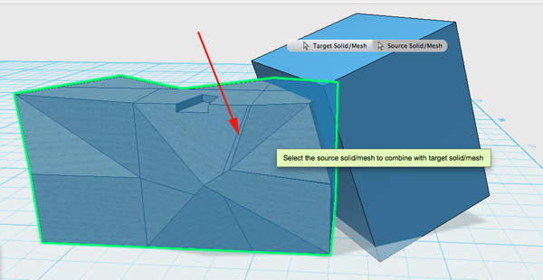
- Select the object you want to keep:
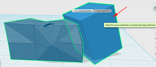
- Select the object you want to delete:
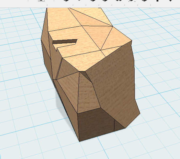
- Pree RETURN:
- Save your model
- Export as STL
- Move on to the next station.
