Introduction
OpenSCAD is an open source parametric design tool for creating solid 3D CAD objects. The application supports Constructive Solid Geometry (CSG) modeling through text commands. It is free and available for Linux/UNIX, MS Windows and Mac OS X.OpenSCAD focuses on the CAD aspects of 3D modeling and is good for creating 3D models of machine parts or for any part where you want to specify parameters. It is not an interactive modeller. Instead it reads in statements that describe the object and it renders the 3D model from that code. This gives you full control over the modelling process and enables you to easily change any step in the process or make designs that are defined by configurable parameters.
OpenSCAD provides two main modelling techniques:
- Constructive Solid Geometry
- Extrusion of 2D outlines
Numbers in OpenSCAD are in millimeters. So circle(5); or circle(r=5); draws a circle with a radius of 5mm. If you do not have OpenSCAD installed yet, download the latest Development Snapshot from openscad.org
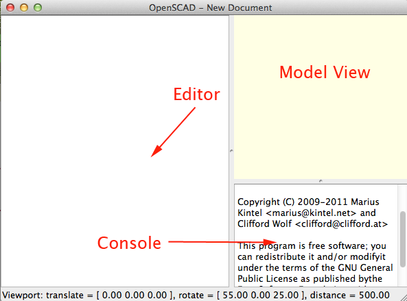
When you open OpenSCAD you will see the interface:
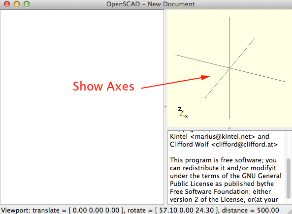
To display the axes in the model view press Command+2 (MAC) or CTRL+2 (Windows and Linux).
Statements in OpenSCAD end with a semi-colon.
cube([10,10,20]);
OpenSCAD does not automatically indent your code, but you are encouraged to use indents for readability
difference(){
    cylinder(h = 5, r = 20);
    translate(v=[0,0,-1])
    cylinder(h = 7, r = 4);
}
To comment out a single line begin the comment with a double-slash (//)
//this is a comment

myVar=10;//this is also a single-line comment
To comment out multiple lines, begin the comment with slash-star and end the comment with star-slash:
/* This is a multi-line comment.
I started the comment on the line above.
I will complete the comment on the line below.
*/
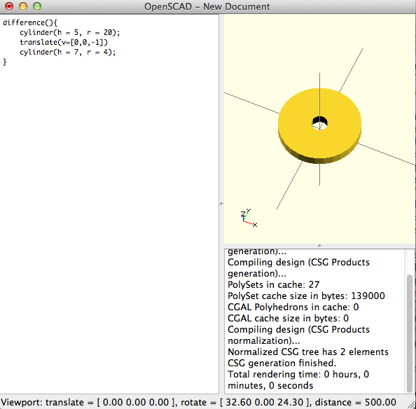
Press F5 to render. This will show you what your model looks like in the model view
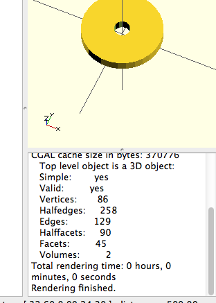
Press F6 to compile and render. This will create a model that is ready to export as an stl file:
You can use %(the Background Modifier) to ignore the subtree for the normal rendering process and draw it in transparent gray. In other words to ghost an object. This is handy when you want to see what is being differenced:
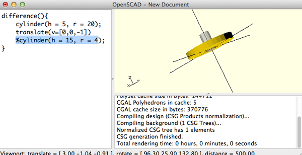
There is also * (the Disable Modifier), which will ignore the entire subtree.
difference() {
        cylinder (h = 4, r=1, center = true, $fn=100);
        *rotate ([90,0,0]) cylinder (h = 4, r=0.9, center = true, $fn=100);
}
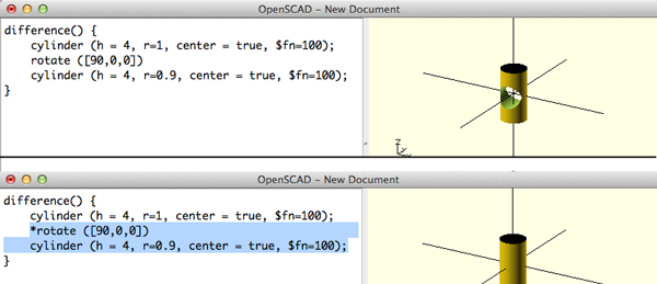
$fn sets the resolution. This can be at the top of your file.
Here is how to set the resolution to 128.
$fn=128;
You can move the rendered object by:
- Dragging with left mouse button to rotate the view. You can see the rotate values at the bottom of the window.
- Dragging with the right mouse button to translate (move) the view. You can see the translate values in the bottom of the window.
- Dragging north and south with the right mouse while holding down the SHIFT key. will zoom in and out.
- Using the mouse scroll to zoom in and out. The Viewport line at the bottom of the window will show a change in the distance value.
-
Use the following quick key combinations to control the view:
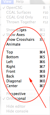
- If you get lost, click View>Reset View
View Options
Show Edges (CTRL/⌘+1)
If Show Edges is enabled, both OpenCSG and CGAL mode will render edges as well as faces, CGAL will even show vertices. In CGAL grid mode, this option has no effect.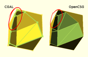
Enabling this option shows the difference between OpenCSG and CGAL quite clearly: While in CGAL mode you see an edge drawn everywhere it belongs, OpenCSG will not show edges resulting from boolean operations – this is because they were never explicitly calculated but are just where one object's Z clipping begins or ends.
Show Axes (CTRL/⌘+2)
If Show Axes is enabled, the origin of the global coordinate system will be indicated by an orthogonal axes indicator. Additionally, a smaller axes indicator with axes names will be shown in the lower left corner of the viewing area. The smaller axes indicator is marked x, y, z and coloured red, green, blue respectively.Show Crosshairs (CTRL/⌘+3)
If Show Crosshairs is enabled, the center of the viewport will be indicated by four lines pointing in the room diagonal directions of the global coordinate system. This is useful when aligning the viewing area to a particular point in the model to keep it centered on screen during rotation.Animation
The Animate option adds an animation bar to the lower edge of the screen. As soon as FPS and Steps are set (reasonable values to begin with are 10 and 100, respectively), the current Time is incremented by 1/Steps, FPS times per second, until it reaches 1, when it wraps back to 0.Every time Time is changed, the program is re-evaluated with the variable $t set to the current time.
To see how animate works, download spiderbot and run the main.scad files
Importing an stl file
To bring in an stl file:- make sure the file is watertight.
- Make sure your scad file is saved and you know its path
- Use this syntax:
import("path/example.stl");
Primitives
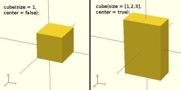
cube(size, center)
Creates a cube at the origin of the coordinate system. When center is true the cube will be centered on the origin, otherwise it is created in the first quadrant.The argument names (size, center) are optional as long as the arguments are given in the same order as specified in the parameters. This why the following statements all create the same cube:
cube(size=10);
cube(10);
cube([10,10,10]);
cube([10,10,10], center=false);
cube(center=false, size=10);
cube( size=10,center=false);
Cube Parameters
sizeSize can be a decimal or a 3 value array. If a single number is given, the result will be a cube with sides of that length. If a 3 value array is given, then the values will correspond to the lengths of the X, Y, and Z sides. If you do not specify a size it will default to 1.
center
This is a Boolean, so it either set to true or false. This property determines the positioning of the object. If set to true, the object is centered at (0,0,0). Otherwise, the the object is placed in the positive quadrant with one corner at (0,0,0). The default is set to false.
Usage examples:
cube(size = 1, center = false);
cube(size = [1,2,3], center = true);
sphere(r)
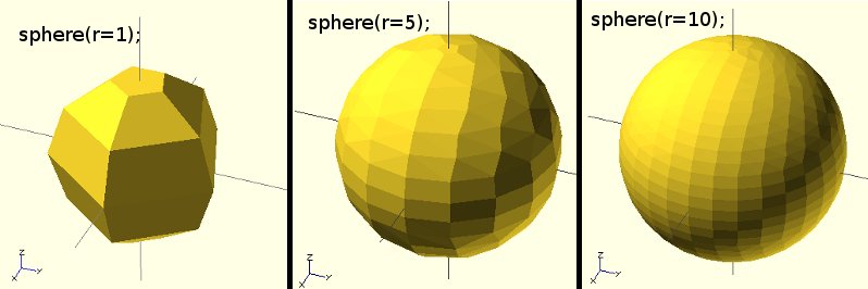
Creates a sphere at the origin of the coordinate system. The argument name is optional.Sphere Parameters
rr is a decimal. This is the radius of the sphere. The resolution of the sphere will be based on the size of the sphere and the $fa, $fs and $fn variables. Usage examples:
sphere(r = 1);
sphere(r = 5);
sphere(r = 10);
sphere(2, $fn=100); // this will create a high resolution sphere with a 2mm radius

sphere(2, $fa=5, $fs=0.1); // will also create a 2mm high resolution sphere but this one does not have as many small triangles on the poles of the sphere
 $fa, $fs and $fn are special variables that control the number of facets used to generate an arc:
$fa is the minimum angle for a fragment. Even a huge circle does not have more fragments than 360 divided by this number. The default value is 12 (i.e. 30 fragments for a full circle). The minimum allowed value is 0.01. Any attempt to set a lower value will cause a warning.
$fs is the minimum size of a fragment. Because of this variable very small circles have a smaller number of fragments than specified using $fa. The default value is 2. The minimum allowed value is 0.01. Any attempt to set a lower value will cause a warning.
$fn is usually 0. When this variable has a value greater than zero, the other two variables are ignored and full circle is rendered using this number of fragments.
When $fa and $fs are used to determine the number of fragments for a circle, then OpenSCAD will never use less than 5 fragments.
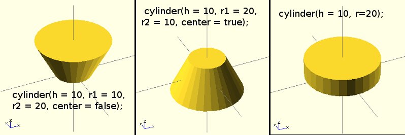
cylinder()
Creates a cylinder at the origin of the coordinate system. When both radii are same it is also possible to specify a single radius by using the argument name r. Use argument names when defining cylinders.Cylinder Parameters
hh is a decimal. This is the height of the cylinder. Default value is 1.
r1
r1 is a decimal. This is the radius of the cylinder/cone on bottom end. Default value is 1.
r2
r2 is a decimal. This is the radius of the cylinder/cone on top end. Default value is 1.
r
Decimal. The radius of both top and bottom ends of the cylinder. Use this parameter if you want a non-cone shaped cylinder. Default value is 1.
$fa
$fa is angle in degrees
$fs
$fs is angle in mm Usage examples:
cylinder(h = 10, r1 = 10, r2 = 20, center = false);
cylinder(h = 10, r1 = 20, r2 = 10, center = true);
cylinder(h = 10, r=20);
cylinder(h = 10, r=20, $fs=6);
Helpful Tip: The $fn parameter dictates how many facets the circumference of your cylinder will have. A cylinder with 8 facets will look like an octagon and a cylinder with 128 facets would probably look almost perfectly circular. You can make triangles by creating cylinders with $fn=3 or just three facets. This is a quick and simple way to get an equilateral triangle.
cylinder(h=10,r=10,$fn=3, center=true);

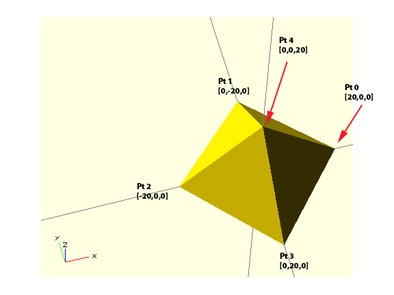
polyhedron()
Create a polyhedron with a list of points and a list of faces. The point list is all the vertices of the shape, the faces list is how the points relate to the surfaces of the polyhedron. Usage examples:polyhedron(points = [ [x, y, z], ... ], triangles = [ [p1, p2, p3..], ... ], convexity = N);
polyhedron(
points=[ [20,0,0],[0,-20,0],[-20,0,0],[0,20,0], // the four points at base
[0,0,20] ], // the apex point
faces=[ [0,1,4],[1,2,4],[2,3,4],[3,0,4],[0,2,1],[1,3,0] ] // two triangles for square base
);
Your First Model
- Open OpenSCAD.
- Type the following into the editor window:
cube([5,5,4]);
- Make sure that when you render, you see the axes. If you do not see them, turn on Show Axes under the View Menu or press Command+2 (MAC) or CTRL+2 (Windows and Linux).
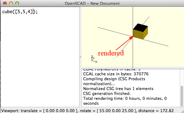
- You should notice that the object is rendered in the first quadrant. By adding center=true to the first statement, you can center the cube on the axes lines:
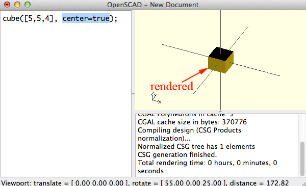
- To create another cube, you could copy and paste the line of code. You will have two cubes , but you won't see the second cube.
Why not?
You won't see the second cube because both cubes are occupying the same space.
To move the second cube away, you have to call translate().
This line is a bit weird because it doesn't end in a semi-colon.
Why not?
It doesn't have a semi-colon because the translate() call is part of the cube statement:cube([5,5,4]); translate([6,0,0]) cube([5,5,4], center=true);
- color() like translate()
is part of the object statement.
Here is how you would make the second object red:cube([5,5,4]); translate([6,0,0]) color([1,0,0]) cube([5,5,4]);
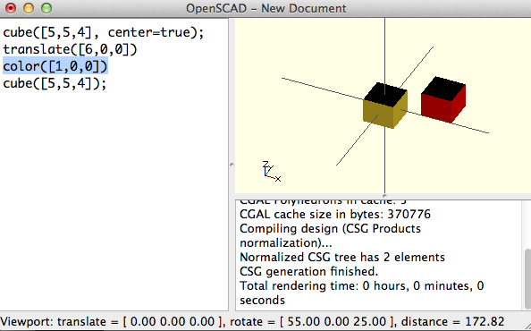
While the color of your model in OpenSCAD does not determine how your model will print, it is nice to be able to control the colors. To change the color use the following syntax:or//using color names color("name_of_color_from_list_below") cube([5,5,4], center=true);A chart of the color names is as follows://using RGB values from 0-1.0 color([1,0,0]) cube([5,5,4]);
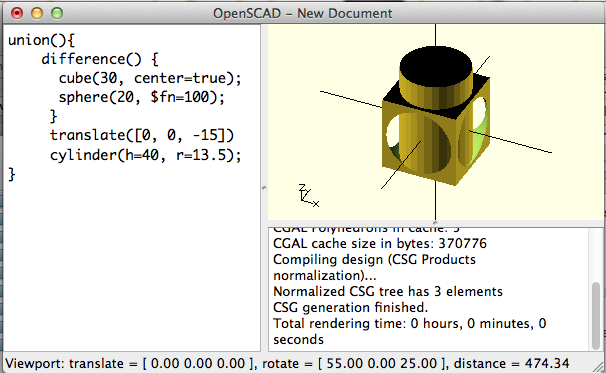
Purples Lavender Thistle Plum Violet Orchid Fuchsia Magenta MediumOrchid MediumPurple BlueViolet DarkViolet DarkOrchid DarkMagenta Purple Indigo DarkSlateBlue SlateBlue MediumSlateBlue Pinks Pink LightPink HotPink DeepPink MediumVioletRed PaleVioletRed Blues Aqua Cyan LightCyan PaleTurquoise Aquamarine Turquoise MediumTurquoise DarkTurquoise CadetBlue SteelBlue LightSteelBlue PowderBlue LightBlue SkyBlue LightSkyBlue DeepSkyBlue DodgerBlue CornflowerBlue RoyalBlue Blue MediumBlue DarkBlue Navy MidnightBlue Reds IndianRed LightCoral Salmon DarkSalmon LightSalmon Red Crimson FireBrick DarkRed Greens GreenYellow Chartreuse LawnGreen Lime LimeGreen PaleGreen LightGreen MediumSpringGreen SpringGreen MediumSeaGreen SeaGreen ForestGreen Green DarkGreen YellowGreen OliveDrab Olive DarkOliveGreen MediumAquamarine DarkSeaGreen LightSeaGreen DarkCyan Teal Oranges LightSalmon Coral Tomato OrangeRed DarkOrange Orange Yellows Gold Yellow LightYellow LemonChiffon LightGoldenrodYellow PapayaWhip Moccasin PeachPuff PaleGoldenrod Khaki DarkKhaki Browns Cornsilk BlanchedAlmond Bisque NavajoWhite Wheat BurlyWood Tan RosyBrown SandyBrown Goldenrod DarkGoldenrod Peru Chocolate SaddleBrown Sienna Brown Maroon Whites White Snow Honeydew MintCream Azure AliceBlue GhostWhite WhiteSmoke Seashell Beige OldLace FloralWhite Ivory AntiqueWhite Linen LavenderBlush MistyRose Grays Gainsboro LightGrey Silver DarkGray Gray DimGray LightSlateGray SlateGray DarkSlateGray Black - Replace the cubes with the following lines of code and render:
union(){
    difference() {
      cube(35, center=true);
      sphere(20, $fn=100);
     }
     translate([0, 0, -20])
	 color("red")
     cylinder(h=40, r=13.5);
}
- Now add this line to the very beginning:
And re-render:
$fn=64;
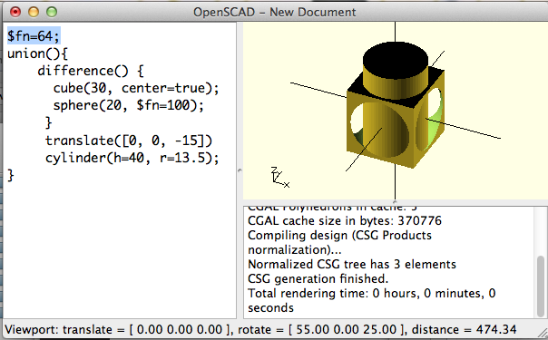
union(), difference() and intersection() are examples of boolean operations
union() creates a union of all the child nodes.union() { cylinder (h = 4, r=1, center = true, $fn=100); rotate ([90,0,0]) cylinder (h = 4, r=0.9, center = true, $fn=100); }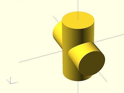
difference() subtracts the second (and all further) child nodes from the first.difference() { cylinder (h = 4, r=1, center = true, $fn=100); rotate ([90,0,0]) cylinder (h = 4, r=0.9, center = true, $fn=100); }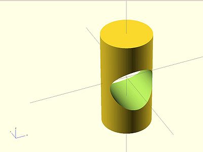
intersection() creates the intersection of all child nodes and keeps the overlapping portion:intersection() { cylinder (h = 4, r=1, center = true, $fn=100); rotate ([90,0,0]) cylinder (h = 4, r=0.9, center = true, $fn=100); }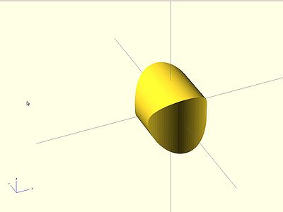
$fn=64;
union(){
    difference() {
      cube(35, center=true);
      sphere(20, $fn=100);
	 color("red")
     union() {
        cylinder (h = 40, r=13.5, center = true, $fn=100);
        rotate ([90,0,0]) cylinder (h = 40, r=13.5, center = true, $fn=100);
		}
	}
}
- mirror() is another transform function. Here is how it works:

Exercise 1
Create a simple heart.- You can use 2D shapes and extrude them or 3D objects:
Here is half a hear using 2D shapes:
color("DarkRed"){
linear_extrude(height=12){
     	square([12,12]);
     	translate([6,0,0])
     	circle(r=6);
	}
}
-
 When you finish the heart, change your code to use a variable:
//partial code s=12; color("DarkRed"){ linear_extrude(height=s){ square([s,s]); translate([s/2,0,0]) circle(r=s/2); } } - Save the finished file as heart.scad
- The following lines of code will create a cylinder 5mm high with a diameter of 40.
An 8mm cylinder is cut out of the center. Notice that the second cylinder has a height of 7 and is translated by -1 on the z-axis. This ensures that the cut is not exactly aligned with the first cylinder and the cut is clean:$fn=64; difference(){ cylinder(h = 5, r = 20); translate(v=[0,0,-1]) cylinder(h = 7, r = 4); }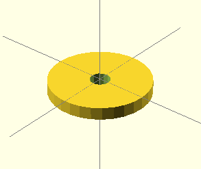
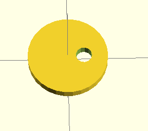
- Use translate to move the smaller cylinder to the right:
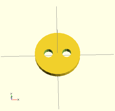
- Cut out another cylinder on the left:
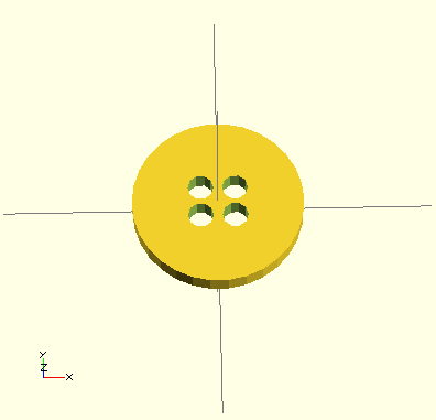
- Create 4 holes:
- Now make this shape:

You'll have to remove a sphere: sphere(r=5,$fn=100);
You could even try getting fancy by combining a cone, sphere and cylinder.
- Compile and Render (F6)
- Export as STL (File>Export>Export as STL). Save the file when it tells you to.
Exercise 2
Modules
A module in OpenSCAD is similar to a macro or a function in other languages. Creating a module allows you to easily reuse code and to create parametric models.To define a module:
module Name_of_module(param1,param2,...){
//statements...
}
- Open your heart.scad
- You want to make the heart code a module:
module heart(s=12, c="DarkRed"){ color(c){ linear_extrude(height=s){ square([s,s]); translate([s/2,0,0]) circle(r=s/2); translate([0,s/2,0]) circle(r=s/2); } } } - If you run the code you will get an error because nothing is being drawn. To fix this, outside the module type
heart(20, "Blue");
- Add more parameters: how about size, height and color so that you can get diffferent kinds of hearts:

- Try adding a twist:
linear_extrude( height = h, twist = 125, scale = .5) {
As the extrusion stretches out the 2D shape, it starts at a scale of 1: 1 and then makes it so that at the end it will be at the specified scaling factor. Scale reduces to zero over the length of the object, but you could grow the scale, instead. Try changing scale to 10, or use a vector [2,10] You can specify default values in your definition like this:module house(roof="flat", paint=[1,0,0]){ color(paint) if(roof=="flat"){ translate([0,-1,0]) cube(); }else if( roof=="pitched"){ rotate([90,0,0]) linear_extrude(height=1) polygon(points=[[0,0],[0,1],[0.5,1.5],[1,1],[1,0]],paths=[ [0,1,2,3,4] ]); }else if(roof=="domical"){ translate([0,-1,0]) union(){ translate([0.5,0.5,1]) sphere(r=0.5,$fn=20); cube(); } } }
To use the module:house(); translate([1,0,0]) house("pitched", [0,1,0]);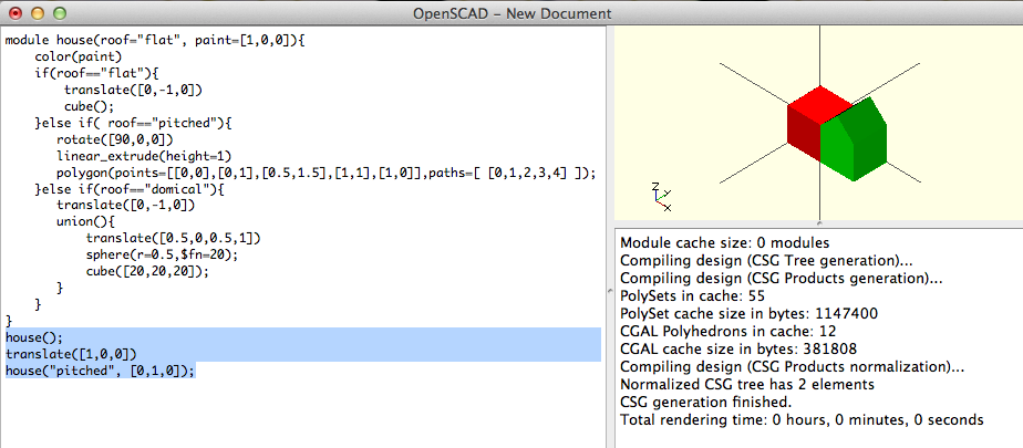
Save the file as house.scadUsing Variables
Variables allow your modules to be parametric. roof and paint are variables, but you could add more:module house(roof="flat", paint=[1,0,0], s=20){ color(paint) if(roof=="flat"){ translate([0,-s,0]) cube(s); }else if( roof=="pitched"){ rotate([90,0,0]) linear_extrude(height=s) polygon(points=[[0,0],[0,s],[s/2,3*s/2],[s,s],[s,0]],paths=[ [0,1,2,3,4] ]); }else if(roof=="domical"){ translate([0,-s,0]) union(){ translate([s/2,s/2,s]) sphere(r=s/2,$fn=20); cube(s); } } } house(); translate([40,0,0]) house("pitched", s=10); translate([80,0,0]) house("domical",[0,1,1]); translate([0,40,0]) house(roof="pitched",paint=[0,0,1], 30); translate([0,120,0]) house(paint=[0,0,0],roof="pitched", s=50); translate([60,40,0]) house(roof="domical"); translate([80,60,0]) house(paint=[0,.5,.2], s=15);
More Examples: Creating another Module
- Open OpenSCAD
- In the editor add code to define the name of a module. The module should be called join_two_points. This module will take the following parameters:
- x1
- y1
- z1
- x2
- y2
- z2
- diameter
- You will use the distance formula to create the value for a variable called length.
Inside the module, create a variable called length and set it to

sqrt( pow(x1 - x2, 2) + pow(y1 - y2, 2) + pow(z1 - z2, 2) );
- Tertiary syntax allows you to test a conditional and assign a value based on the evaluation in one line:
You want to determine if the difference between the y1 and y2 is not 0. If this condition is met than you want to set alpha to the inverse tangent (arctangent) of (z2 - z1) / (y2 - y1).
//if a is less than b then set the string to "hello" //if a is not less than b then set the string to "good bye" ((a<b) ? string="hello": string="good bye");
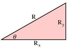
The arctangent is used to calculate the angles of a right triangle. It will return the angle of the given ratio.
To illustrate arctangent, start with a right triangle with sides a and b. The typical way to use the tangent function is to calculate the ratio of the two non-hypotenuse sides of a right triangle, such as a and b, from the angle (θ) between b and the hypotenuse. This is indicated as tan(θ) = b / a.
arctangent works in the opposite direction; you can use the ratio b / a to find the angle θ, such that θ = atan(b / a).
 Create a variable named beta and if x2- x1 does not equal 0 than set beta to 90-atan( (z2 - z1) / (x2 - x1) ) otherwise set it to 90- 0.
- Create a variable named gamma and if x2- x1 does not equal 0 than
set gamma to atan( (y2 - y1) / (x2 - x1)
Otherwise
set gamma to ( (y2 - y1 >= 0) ? 90 : -90 ) ) + ( (x2 - x1 >= 0) ? 0 : -180 ) - To display values of variables, you use the keyword echo
echo(Length = length, Alpha = alpha, Beta = beta, Gamma = gamma);
- Call translate() and translate the object by x1, y1, z1
- Call rotate() and rotate the object by 0, beta, gamma
- Create a cylinder where the height = length and radius = diameter/2
- To use the module you specify the starting x, y and z and the ending x, y and z:
join_two_points(0, 0, 0, 50, 0, 0, 5 ); // +X join_two_points( 50, 0, 0, 50, 50, 0, 5 ); // -X join_two_points( 50, 50, 0, 0, 50, 0, 5 ); // +Y join_two_points( 0, 50, 0, 0, 0, 0, 5 ); // -Y join_two_points( 0, 0, 0, -50, -50,0, 5 ); // -X -Y join_two_points( 0, 0, 0, 50, 50, 50, 5 ); // +XYZ

- Here is the module to add rounded corners:
module corner(x, y, z, diameter){ translate([x, y, z]) sphere( r = diameter/2 ); }
- This code:
produces this:
diameter=2; cubeHeight=10; width=50; length=50; innerWidth=20; innerLength=10; translate([-25,-25,-10]){ cube([width,length,cubeHeight]); for(z=[0:2]){ perimeter(width,length,cubeHeight+z*diameter,diameter); } translate([(width-innerWidth)/2,(length-innerLength)/2,0]){ for(z=[0:2]){ perimeter(innerWidth,innerLength,cubeHeight+z*diameter,diameter); } } }
- Complete the program by creating the module perimeter.
- View the model by pressing F5.
- Render and Compile by pressing F6. Then select File>Export >Export as STL
Loops
A for loop is a programming language statement which allows code to be repeatedly executed. Unlike a while loop, the for loop is distinguished by an explicit loop counter or loop variable. You can use a for loop when you can provide the number of iterations. For loops in OpenSCAD allow you to iterate over the values in a vector or range:In the code snippet above the loop iterates 2 times: The first time through i is -1. The second time through the loop i is 1.for (i = [-1, 1]){ translate([0, 0, i]) cube(size = 1, center = false); }
In the code snippet above the loop iterates 6 times: The first time through i is 0. The second time through the loop i is 1. The last time through the loop, i is 5.$fn=64; for ( i = [0 : 5] ){ rotate( i * 60, [1, 0, 0]) translate([0, 10, 0]) sphere(r = 10); }
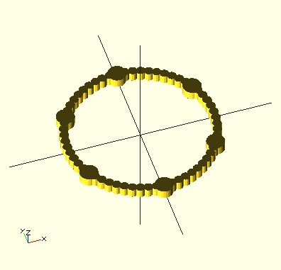
In the code snippet above the loop iterates 30 times. i goes from 0 to 6 by steps of 0.2. The first time through i is 0. The second time through the loop i is 0.2. The third time through i is 0.4. The last time through the loop, i is 6.$fn=64; for ( i = [0 : 0.2 : 6] ){ rotate( i * 60, [1, 0, 0]) translate([0, 10, 0]) sphere(r = 1); }
for (i = [0:5]) {
    echo(360*i/6, sin(360*i/6)*80, cos(360*i/6)*80);
    translate([sin(360*i/6)*80, cos(360*i/6)*80, 0 ])
    cylinder(h = 10, r=10);
}
for (i =  [0 : 0.1 : 6]) {
    echo(360*i/6, sin(360*i/6)*80, cos(360*i/6)*80);
    translate([sin(360*i/6)*80, cos(360*i/6)*80, 0 ])
    cylinder(h = 10, r=5);
}
To simplify your code you can use the assign keyword:for (i = [10:50]){ assign (angle = i*360/20, distance = i*10, r = i*2){ rotate(angle, [1, 0, 0]) translate([0, distance, 0]) sphere(r = r); } }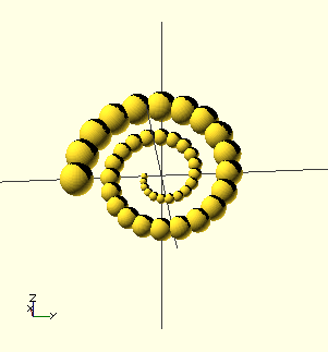
Here is an example that uses a module to line up objects by number and space. In order to use this module with an object, you must use child(0). child is referring to the cube() in this example:module lineup(num, space) { for (i = [0 : num-1]) translate([ space*i, 0, 0 ]) child(0); } lineup(7, 22) cube(20);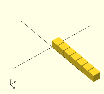
If you need to make your module iterate over all children you need to make use of the $children variablemodule elongate(){ for (i = [0 : $children-1]){ scale([10 , 1, 1 ]) child(i); } } elongate() { sphere(30); cube([10,10,10]); cylinder(r=10,h=50); }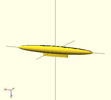
Another example that uses $children://this code is from example018.scad in the application's example directory module step(len, mod) { for (i = [0:$children-1]) translate([ len*(i - ($children-1)/2), 0, 0 ]) child((i+mod) % $children); } for (i = [1:4]) { translate([0, -250+i*100, 0]) step(100, i) { sphere(30); cube(60, true); cylinder(r = 30, h = 50, center = true); union() { cube(45, true); rotate([45, 0, 0]) cube(50, true); rotate([0, 45, 0]) cube(50, true); rotate([0, 0, 45]) cube(50, true); } } }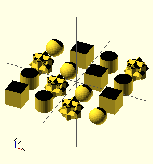
Libraries
OpenSCAD allows you to create files that contain a series of modules. You can then use one of two keywords use or include to incorporate those modules into another file.
- Create a new SCAD file and save it in the same directory as your house.scadfile
- On the first line write:
include <house.scad>
- Press F5
- Now change include to use and your second line shoud be:
house("pitched", "SlateBlue", 40); - Press F5
 member Tony Buser created a scad file called pins.scad. This file contains several modules:
- pinhole(h=10, r=4, lh=3, lt=1, t=0.3, tight=true)
Where:h = shaft height
r = shaft radius
lh = lip height
lt = lip thickness
t = tolerance
tight = set to false if you want a joint that spins easily
- pin(h=10, r=4, lh=3, lt=1, side=false)
Where:h = shaft height
r = shaft radius
lh = lip height
lt = lip thickness
side = set to true if you want it printed horizontally
- pintack(h=10, r=4, lh=3, lt=1, bh=3, br=8.75)
Where:h = shaft height
r = shaft radius
lh = lip height
lt = lip thickness
bh = base_height
br = base_radius
- pinpeg(h=20, r=4, lh=3, lt=1)
Where:h = shaft height
r = shaft radius
lh = lip height
lt = lip thickness
- pin_vertical(h=10, r=4, lh=3, lt=1)
Where:h = shaft height
r = shaft radius
lh = lip height
lt = lip thickness - pin_horizontal(h=10, r=4, lh=3, lt=1)
Where:h = shaft height
r = shaft radius
lh = lip height
lt = lip thickness
- pin_solid(h=10, r=4, lh=3, lt=1)
Where:h = shaft height
r = shaft radius
lh = lip height
lt = lip thickness
- test()
If you just compiled this program you would get the following error:// Pin Connectors V2 // Tony Buser <tbuser@gmail.com> module test() { tolerance = 0.3; translate([-12, 12, 0]) pinpeg(h=20); translate([12, 12, 0]) pintack(h=10); difference() { union() { translate([0, -12, 2.5]) cube(size = [59, 20, 5], center = true); translate([24, -12, 7.5]) cube(size = [12, 20, 15], center = true); } translate([-24, -12, 0]) pinhole(h=5, t=tolerance); translate([-12, -12, 0]) pinhole(h=5, t=tolerance, tight=false); translate([0, -12, 0]) pinhole(h=10, t=tolerance); translate([12, -12, 0]) pinhole(h=10, t=tolerance, tight=false); translate([24, -12, 15]) rotate([0, 180, 0]) pinhole(h=10, t=tolerance); } } module pinhole(h=10, r=4, lh=3, lt=1, t=0.3, tight=true) { // h = shaft height // r = shaft radius // lh = lip height // lt = lip thickness // t = tolerance // tight = set to false if you want a joint that spins easily union() { pin_solid(h, r+(t/2), lh, lt); cylinder(h=h+0.2, r=r); // widen the cylinder slightly // cylinder(h=h+0.2, r=r+(t-0.2/2)); if (tight == false) { cylinder(h=h+0.2, r=r+(t/2)+0.25); } // widen the entrance hole to make insertion easier translate([0, 0, -0.1]) cylinder(h=lh/3, r2=r, r1=r+(t/2)+(lt/2)); } } module pin(h=10, r=4, lh=3, lt=1, side=false) { // h = shaft height // r = shaft radius // lh = lip height // lt = lip thickness // side = set to true if you want it printed horizontally if (side) { pin_horizontal(h, r, lh, lt); } else { pin_vertical(h, r, lh, lt); } } module pintack(h=10, r=4, lh=3, lt=1, bh=3, br=8.75) { // bh = base_height // br = base_radius union() { cylinder(h=bh, r=br); translate([0, 0, bh]) pin(h, r, lh, lt); } } module pinpeg(h=20, r=4, lh=3, lt=1) { union() { translate([0, -h/4+0.05, 0]) pin(h/2+0.1, r, lh, lt, side=true); translate([0, h/4-0.05, 0]) rotate([0, 0, 180]) pin(h/2+0.1, r, lh, lt, side=true); } } // just call pin instead, I made this module because it was easier to do the rotation option this way // since openscad complains of recursion if I did it all in one module module pin_vertical(h=10, r=4, lh=3, lt=1) { // h = shaft height // r = shaft radius // lh = lip height // lt = lip thickness difference() { pin_solid(h, r, lh, lt); // center cut translate([-r*0.5/2, -(r*2+lt*2)/2, h/4]) cube([r*0.5, r*2+lt*2, h]); translate([0, 0, h/4]) cylinder(h=h+lh, r=r/2.5, $fn=20); // center curve // translate([0, 0, h/4]) rotate([90, 0, 0]) cylinder(h=r*2, r=r*0.5/2, center=true, $fn=20); // side cuts translate([-r*2, -lt-r*1.125, -1]) cube([r*4, lt*2, h+2]); translate([-r*2, -lt+r*1.125, -1]) cube([r*4, lt*2, h+2]); } } // call pin with side=true instead of this module pin_horizontal(h=10, r=4, lh=3, lt=1) { // h = shaft height // r = shaft radius // lh = lip height // lt = lip thickness translate([0, h/2, r*1.125-lt]) rotate([90, 0, 0]) pin_vertical(h, r, lh, lt); } // this is mainly to make the pinhole module easier module pin_solid(h=10, r=4, lh=3, lt=1) { union() { // shaft cylinder(h=h-lh, r=r, $fn=30); // lip // translate([0, 0, h-lh]) cylinder(h=lh*0.25, r1=r, r2=r+(lt/2), $fn=30); // translate([0, 0, h-lh+lh*0.25]) cylinder(h=lh*0.25, r2=r, r1=r+(lt/2), $fn=30); // translate([0, 0, h-lh+lh*0.50]) cylinder(h=lh*0.50, r1=r, r2=r-(lt/2), $fn=30); // translate([0, 0, h-lh]) cylinder(h=lh*0.50, r1=r, r2=r+(lt/2), $fn=30); // translate([0, 0, h-lh+lh*0.50]) cylinder(h=lh*0.50, r1=r+(lt/2), r2=r-(lt/3), $fn=30); translate([0, 0, h-lh]) cylinder(h=lh*0.25, r1=r, r2=r+(lt/2), $fn=30); translate([0, 0, h-lh+lh*0.25]) cylinder(h=lh*0.25, r=r+(lt/2), $fn=30); translate([0, 0, h-lh+lh*0.50]) cylinder(h=lh*0.50, r1=r+(lt/2), r2=r-(lt/2), $fn=30); // translate([0, 0, h-lh]) cylinder(h=lh, r1=r+(lt/2), r2=1, $fn=30); // translate([0, 0, h-lh-lt/2]) cylinder(h=lt/2, r1=r, r2=r+(lt/2), $fn=30); } }

To fix this error you need to call one of the modules:pintack(10);
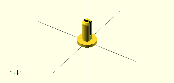
To use the pins.scad file in another file- Save both files in the same directory.
- The first line in your second file should use include or use
include will bring the entire file into the new file.include <pins.scad>
If you just want to use a module from one file in another consider using:use imports modules and functions, but does not execute any commands other than those definitions.use <pins.scad>
MCAD Libraries
If you have downloaded the latest Development Snapshot, the application folder will contain the MCAD library:
There are several files within the MCAD folder:
In order to use an MCAD file, you need to specify which file in the first lines of your OpenSCAD file:use <MCAD/boxes.scad> roundedBox([30, 30, 40], 5, true);
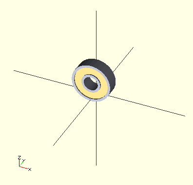
bearing.scad
test_bearing() displays a 608 bearing inside a test_bearing_hole.
test_bearing_hole() displays a a cube (size=[30, 30, 7-10*epsilon] ) to hold a bearing.
bearingDimensions(model) Sets the dimensions for the following bearing numbers. 608 (Skatebearing) is the model default.
608 = [8*mm, 22*mm, 7*mm]
623 = [3*mm, 10*mm, 4*mm]
624 = [4*mm, 13*mm, 5*mm]
627 = [7*mm, 22*mm, 7*mm]
688 = [8*mm, 16*mm, 4*mm]
698 = [8*mm, 19*mm, 6*mm]
bearing(pos=[0,0,0], angle=[0,0,0], model=SkateBearing, outline=false, material=Steel, sideMaterial=Brass)
examplebearing([0,0,10],[90,0,0]);
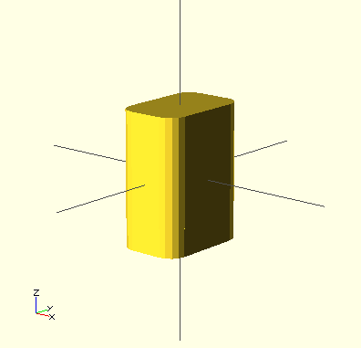
boxes.scad
roundedBox([width, height, depth], float radius, bool sidesonly)
exampleroundedBox([20, 30, 40], 5, true)
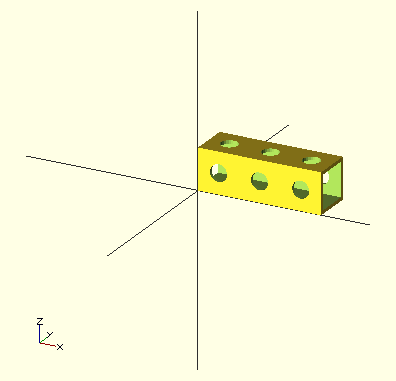
gridbeam.scad
zBeam(segments) create a vertical gridbeam strut 'segments' long
xBeam(segments) create a horizontal gridbeam strut along the X axis
yBeam(segments) create a horizontal gridbeam strut along the Y axis
topShelf(width, depth, corners) create a shelf suitable for use in gridbeam structures width and depth in 'segments', corners == 1 notches corners
bottomShelf(width, depth, corners) like topShelf, but aligns shelf to underside of beams
backBoard(width, height, corners) create a backing board suitable for use in gridbeam structures width and height in 'segments', corners == 1 notches corners
frontBoard(width, height, corners) like backBoard, but aligns board to front side of beams
translateBeam([x, y, z]) translate gridbeam struts or shelves in X, Y, or Z axes in units 'segments'
examplexBeam(3)
metric_fastners.scad
cap_bolt(dia,len)
csk_bolt(dia,len)
washer(dia)
flat_nut(dia)
bolt(dia,len)
cylinder_chamfer(r1,r2)
chamfer(len,r)
exampletranslate([-20,0,0]) csk_bolt(3,14); translate([-10,0,0]) washer(3); translate([0,0,0]) flat_nut(3); translate([10,0,0]) bolt(4,14); translate([-15,-12,0]) cylinder_chamfer(8,1); translate([0,-15,0]) chamfer(10,2);

motors.scad
exampleregular_shapes.scad
triangle(radius);
reg_polygon(sides,radius);
hexagon(radius);
heptagon(radius);
octagon(radius);
nonagon(radius);
decagon(radius);
hendecagon(radius);
dodecagon(radius);
ellipse(width, height);
egg_outline(width, length);
cone(height, radius, center = false) ;
oval_prism(height, rx, ry, center = false) ;
oval_tube(height, rx, ry, wall, center = false) ;
cylinder_tube(height, radius, wall, center = false) ;
tubify(radius,wall);
triangle_prism(height,radius);
triangle_tube(height,radius,wall);
pentagon_prism(height,radius);
pentagon_tube(height,radius,wall);
hexagon_prism(height,radius) ;
heptagon_prism(height,radius) ;
octagon_prism(height,radius) ;
nonagon_prism(height,radius);
decagon_prism(height,radius);
hendecagon_prism(height,radius);
dodecagon_prism(height,radius);
torus(outerRadius, innerRadius);
triangle_pyramid(radius);
square_pyramid(base_x, base_y,height);
hardware.scad
rod(length, threaded)
screw(length, nutpos, washer, bearingpos = -1)
bearing(position)
nut(position, washer)
washer(position)
rodnut(position, washer)
rodwasher(position)
examplerod(20); translate([rodsize * 2.5, 0, 0]) rod(20, true); translate([rodsize * 5, 0, 0]) screw(10, true); translate([rodsize * 7.5, 0, 0]) bearing(); translate([rodsize * 10, 0, 0]) rodnut(); translate([rodsize * 12.5, 0, 0]) rodwasher(); translate([rodsize * 15, 0, 0]) nut(); translate([rodsize * 17.5, 0, 0]) washer();

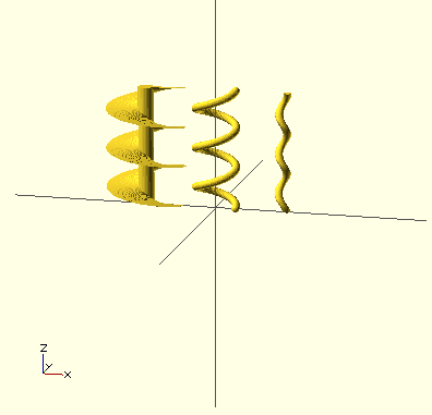
screw.scad
helix(pitch, length, slices=500);
auger(pitch, length, outside_diameter, inner_diameter);
test_auger();
ball_groove(pitch, length, diameter, ball_radius=10);
test_ball_groove();
ball_groove2(pitch, length, diameter, ball_radius, slices=200);
test_ball_groove2();
exampletranslate([-180,0,0]) auger(100, 300); ball_groove2(100, 300, 100, 10); translate([170,0,0]) ball_groove(100, 300, 10);
triangles.scad
triangle(o_len, a_len, depth)
a_triangle(tan_angle, a_len, depth)
exampletriangle(5, 5, 5); translate([10,0,0]) a_triangle(30, 5, 5); translate([20,0,0]) a_triangle(60, 5, 5);
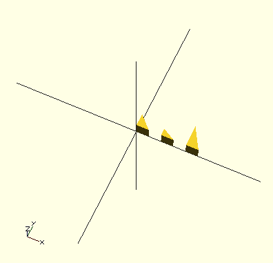
teardrop.scad
This script generates a teardrop shape at the appropriate angle to prevent overhangs greater than 45 degrees. The angle is in degrees, and is a rotation around the Y axis. You can then rotate around Z to point it in any direction. Rotation around X or Y will cause the angle to be wrong.
teardrop(radius, length, angle)
exampleteardrop(10, 10, 60);
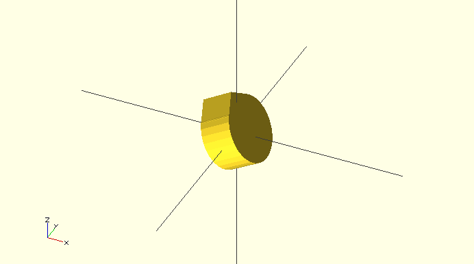
stepper.scad
motor(model=Nema23, size=NemaMedium, dualAxis=false, pos=[0,0,0], orientation = [0,0,0])
examplerotate([0,180,0]) motor(Nema17);
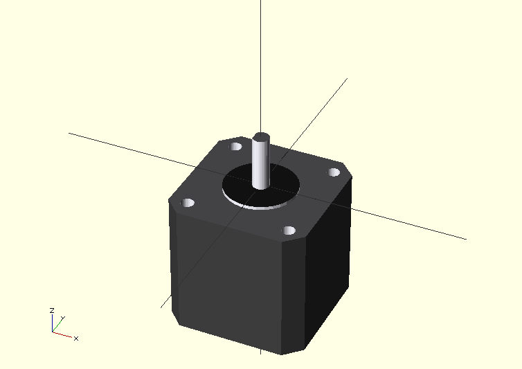
shapes.scad
box(width, height, depth);
roundedBox(width, height, depth, radius);
cone(height, radius, center = false) ;
ellipticalCylinder(w,h, height, center = false);
ellipsoid(w, h, center = false);
tube(height, radius, wall, center = false);
tube2(height, ID, OD, center = false);
ovalTube(height, rx, ry, wall, center = false);
ngon(sides, radius, center=false);
hexagon(size, height);
octagon(size, height);
dodecagon(size, height);
hexagram(size, height);
rightTriangle(adjacent, opposite, height);
equiTriangle(side, height);
12ptStar(size, height);
dislocateBox(w, h, d);
servo.scad
For the Align DS420 digital servo
alignds420(position, rotation, screws = 0, axle_lenght = 0)
examplealignds420(screws=1);

involute_gears.scad
bevel_gear_pair ( gear1_teeth = 41, gear2_teeth = 7, axis_angle = 90, outside_circular_pitch=1000)
bevel_gear ( number_of_teeth=11, cone_distance=100, face_width=20, outside_circular_pitch=1000, pressure_angle=30, clearance = 0.2, bore_diameter=5, gear_thickness = 15, backlash = 0, involute_facets=0, finish = -1)
nvolute_bevel_gear_tooth ( back_cone_radius, root_radius, base_radius, outer_radius, pitch_apex, cone_distance, half_thick_angle, involute_facets)
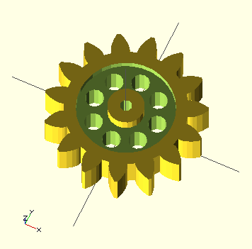
gear ( number_of_teeth=15, circular_pitch=false, diametral_pitch=false, pressure_angle=28, clearance = 0.2, gear_thickness=5, rim_thickness=8, rim_width=5, hub_thickness=10, hub_diameter=15, bore_diameter=5, circles=0, backlash=0, twist=0, involute_facets=0, flat=false)
gear_shape ( number_of_teeth, pitch_radius, root_radius, base_radius, outer_radius, half_thick_angle, involute_facets)
involute_gear_tooth ( pitch_radius, root_radius, base_radius, outer_radius, half_thick_angle, involute_facets)
examplegear (circular_pitch=700, gear_thickness = 12, rim_thickness = 15, hub_thickness = 17, circles=8);
Customizer
Customizer is a simple way on Thingiverse to make customized 3D Things that you can share, download and print. Customizer allows you to design parametric objects that can be customized with an easy web interface. To create your customizer files you need to use OpenSCAD. To share your file, upload your OpenSCAD script to Thingiverse and tag your Thing with the customizer tag.
There are a few things that you need to know about OpenSCAD and Customizer.- Scripts must have all the code they need in a single .scad file and you can only put one .scad file in your Thingiverse entry.
- You cannot import external files (like .stl or .dxf files), but Customizer currently supports the following libraries:
- Build Plate : use <utils/build_plate.scad>
- MCAD: use <MCAD/filename.scad>
- Pin Connectors: use <pins/pins.scad>
- Write.scad: use <write/Write.scad>
This version of Write.scad includes the following fonts:
- write/Letters.dxf
- write/BlackRose.dxf
- write/orbitron.dxf
- You can create your parameters in such a way as to enable drop-down, sliders and text boxes so that a user can change the values.
To create a drop down menu you create an array and separate your values by commas:- Numbers: [0, 1, 2, 3]
- Strings: [foo, bar, baz]
- Labeled values: [10:Small, 20:Medium, 30:Large]
- Whole Numbers only allowed, specify min/max: [0:100]
- Variables that equal other variables or include operations such as + - / * will be ignored and cannot be customized. So the following variables will not result in a form input on the web page:
- x = x / 2;
- height = 4 * 25.4;
- function foo(x) = pow((1-x), 3);
If you need a floating point value from a slider you can create another variable and assign it a value divided by 10. - Parameters should be placed at the top of your script before the first module declaration and should be in the following form:
The variable description comment gives the user an idea of what the parameter defines. This comment is optional and if used will appear in gray:
// variable description comment
variable_name = default value; // possible values

The variable_name will remain as one word in the code, but the user will see spaces substituted for the underscores:

The default value will be what the drop down, slider or text box is set to. If you do not supply a possible values comment the user will be presented with a text box where they can enter any value.:Hole_Diameter=2.5;

The possible values comment at the end is optional. By formatting the possible values, you can define the drop down or slider inputs.
- Some designs look best when viewed from a certain angle. For instance, perhaps your script adds text to the bottom of your object and you want people to see the bottom when the page loads. You can control the default view by adding a comment formatted like this:
The view parameter defaults to "south east" and can take the following values:
// preview[view:south, tilt:top]
- north
- north east
- east
- south east
- south
- south west
- west
- north west
- top
- top diagonal
- side
- bottom diagonal
- bottom
- Avoid using hull() and minkowski() functions if you can. They are slow to calculate and will make the preview update take much longer.
- Avoid using the render() function. It often makes sense when designing an object for the desktop version of openSCAD, but will increase render times for the preview window in Customizer.
- To create multiple parts:
// Which one would you like to see? part = "first"; // [first:Cube Only,second:Cylinder Only,both:Cube and Cylinder] cube_size = 10; // [1:100] cylinder_size = 10; // [1:100] print_part(); module print_part() { if (part == "first") { mycube(); } else if (part == "second") { mycylinder(); } else if (part == "both") { both(); } else { both(); } } module both() { translate([-cube_size, 0, 0]) mycube(); translate([cube_size, 0, 0]) mycylinder(); } module mycube() { translate([0, 0, cube_size/2]) cube(cube_size, center=true); } module mycylinder() { cylinder(r=cube_size/2, h=cylinder_size); } - Customizer provides a special parameter type that allows you to upload an image file. Customizer will turn that image into a grayscale OpenSCAD Surface .dat file. This can be used to for instance create a lithopane, to emboss a pattern or logo on the side of an object in your design, or to visualize a 3D terrain from map data. Here is how you can request a 100 x 100 pixel image from the user:
This will create a .dat file that is 100 x 100 mm in size. Images larger or smaller than the requested size will automatically be stretched to fit. The minimum size is 1x1 and the maximum size is 150x150. If you request a size larger than the maximum, it will fall back to 150. The larger the size, the longer it will take to process, so it's best to keep the size as small as possible. The Z axis will be between 0 and 1 based on a 256 color grayscale range. Black pixels are 0, White pixels are 1, and gray would be 0.5. Therefore, you can request a size and then scale the z axis as needed. Here is a complete example which makes a surface where pure white is 10mm tall and pure black is 0mm:
filename_variable = "foo.dat"; // [image_surface:100x100]
surface(file=filename_variable);
Test it out hereheight = 10; // [1:100] // Load a 100x100 pixel image. (images will be automatically stretched to fit) Simple, high contrast images like logos work best. image_file = "image-surface.dat"; // [image_surface:100x100] scale([1,1,height]) surface(file=image_file, center=true, convexity=5);
- Similar to the Image To Surface parameter, this outputs an array instead of creating a surface() .dat file. Although easy to use, one of the limitations of the OpenSCAD surface() function is that it only creates a flat heightmap. By using Image To Array, you will get an array of values between 0 and 1 for each pixel in an image. This way you can programatically generate more complex shapes based on image data. The array will be a flat array, all rows condensed into a single list. So you'll need to handle looping through each row of the image based on the dimensions you request. Here's the syntax (default value is a circle shape):
Test it out here
image_array = [0.5,0.5,0.5, 0.5,0,0.5, 0.5,0.5,0.5]; // [image_array:3x3]
So where do you start?
- After you decide what you are going to build, you can start with this basic form:
This code contains a call to a module and the beginning of a module definition.
my_object(); module my_object(){ } -
So let's say my object will be a parametric star. I would start with my variables that I would like the user to control:
number_of_points=5;//[5,6,7,8,9,10,11,12,13,14,15,16,17,18,19,20,21,22,23,24]
height=1;//[1:10]
inner_radius=15;//[15:30]
-
Now I want to create an outer radius that is larger than the inner radius. You cannot include the inner_radius in the outer_radius assignment if you want the user to be able to control this value. One solution might be to add a variable description comment:
//The amount added to the inner radius
outer_radius=10;//[1:50]
-
Then you can provide a call to your module:
parametric_star(number_of_points, height, inner_radius, inner_radius+outer_radius) ;
-
And then define the module:
module parametric_star(N, h, ri, re) { //-- Calculate and draw a 2D tip of the star //-- INPUT: //-- n: Number of the tip (from 0 to N-1) module tipstar(n) { i1 = [ri*cos(-360*n/N+360/(N*2)), ri*sin(-360*n/N+360/(N*2))]; e1 = [re*cos(-360*n/N), re*sin(-360*n/N)]; i2 = [ri*cos(-360*(n+1)/N+360/(N*2)), ri*sin(-360*(n+1)/N+360/(N*2))]; polygon([ i1, e1, i2]); } //-- Draw the 2D star and extrude //-- The star is the union of N 2D tips. //-- A inner cylinder is also needed for filling //-- A flat (2D) star is built. The it is extruded linear_extrude(height=h) union() { for (i=[0:N-1]) { tipstar(i); } rotate([0,0,360/(2*N)]) circle(r=ri+ri*0.01,$fn=N); } } -
If your code is derived from someone else, be sure to include that information:
//-- This script was derived from Parametric star
//-- (c)  2010 Juan Gonzalez-Gomez (Obijuan) juan@iearobotics.com
//-- GPL license

//-- The 2*N points of an N-ponted star are calculated as follows:
//-- There are two circunferences:  the inner and outer.  Outer points are located
//-- at angles: 0, 360/N, 360*2/N and on the outer circunference
//-- The inner points have the same angular distance but they are 360/(2*N) rotated
//-- respect to the outers. They are located on the inner circunference
- Save and upload your script. You may find that you need to make adjustments after it is uploaded. Delete the script, edit your code, re-upload you script and test again.
Inkscape &:OpenSCAD
You can import 2D shapes and manipulate them in OpenSCAD. Use a program like Inkscape to create your dxf files.import (file = "example.dxf", layer = "layer_0", origin = center);
Inkscape to sxf to OpenSCAD
- To save the dxf in the right format you'll need to install this plugin.
- Follow the instructions to install the plugin.
- Find an image that you would like to use.

Image from my-favorite-coloring.net - Import your image into Inkscape.
- Under Paths menu select Trace Bitmap:

- Accept the Defaults, press Update , then OK and close the dialog box

- If you want a solid shape save now as a BigBlueSae DXF

- Also save a copy as an SVG in case you want to go back to it.
- For a cookie-cutter effect (the outline of the letter or shape)
- Duplicate the Path. Click on Edit Paths by Nodes then press (CTRL+D)

- Change the fill of the top shape to a new color.

-
Use the Path > Inset command CTRL+( to shrink the copy a few times until you have the thickness you want:

- You should see the difference different colors: the original color will be the edge.

- Once it is how you want, select the original and then use the shift key and select the copy.
- Select Path > Difference to subtract the copy from the original, leaving an outline

- With the select and transform objects tool separate the copies:

- Delete the original

- In open scad use this syntax:
linear_extrude( height = 3, center = true)
import( file ="drawing2.dxf");
- Duplicate the Path. Click on Edit Paths by Nodes then press (CTRL+D)
More Ideas
- Given cubes, cylinders, cones, and spheres you can construct almost anything via a process known as solid constructive geometry. Basically you add and adding and subtract shapes from each other to create another form.
- Customizer Projects:
Lithopanes
Music Box
iPhone Cases
Customizable Things - Use the write.scad library to create models with text
use write.scad with customizer - OpenSCAD and Airfoil database
- OpenSCAD to plot curves
- Create a 3D maze
- Design a customizable QR Code maker
- Explore Polyhedra in OpenSCAD
- A blended classroom: OpenSCAD videos
