Introduction
...learn about design, geometry, production, and CNC (computer numerically controlled) machines. Roland's GX vinyl cutter allows users to create signs, graphics, plastic stickers, 3D pop-up cards, dioramas, silk screening masks, and flexible circuits cut out of adhesive-backed copper foil.
- The vinyl cutter can use vector file information from a variety of programs, such as Adobe Illustrator, Corel Draw, and Inkscape. The vinyl cutter also requires a path to cut. Most of these programs have a path, expand, or trace option. You can also save your image as a PDF.
- Your document size should be no wider than 24 inches and orient in landscape.
- The vinyl cutter uses vector paths to cut. Line thickness will not matter, as long as there is a path to follow. To generate a path that the machine will follow, select your drawing and use the path, expand, or trace tool.
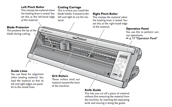
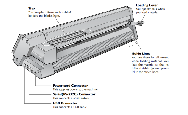
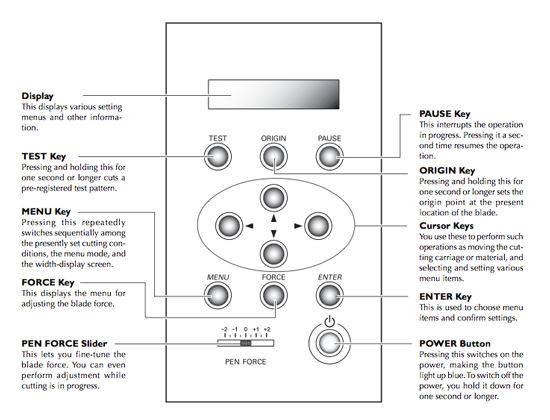
Types of Vinyl Cutters
RolandWhen cutting vinyl use : Force: 160 g/f, Speed: 20cm/sec Set Document units to MM B&W png or SVG GX-24
- Accepts material from 2 to 27.5 inches wide
- Mechanical Resolution of 0.0005
- Cutting Speeds of up to 20 inches per second
- Maximum down force of 250 grams
Material
- Vinyl or Copper sheets
- Utility knife
- Scissors
- Fine Tweezers(for weeding)
- Transfer tape
- Magnifying Glass
Software
- Illustrator
- Inkscape
- Roland Cutstudio
Flexible Circuits
You can use a vinyl cutter and adhesive-backed copper foil to create flexible PCBs.
While you can make flexible circuits, circuits cut with the Roalnd Vinyl Cutter are limited due to the width of the knife. Generally anything that can be cut with an x-acto knife can be cut with the vinyl cutter, but when making circuits be careful about cuts and details that are too small.
You want to use enough force to cut through the copper, but not through the backing. If you use too much force, the traces will also be dragged up with the cutting. Set the pen force to approximately 45 when the knife is sticking out about 1mm. You can also dynamically adjust the pen force with the slider located on the right control panel of the machine. Adjust the pen force to be lighter for smaller traces and heavier for larger ones tends to work pretty well.
Vinylcut Copper Fabric PCBs
The circuit used in this example was designed in Eagle by Nathalie Krueger of the Design Research Lab at UdK Berlin.- Prepare your vector graphics files. You will need one SVG for cutting the traces of the circuit from copper tape and another for cutting your solder-mask from fabric or tape with adhesive or iron-on backing.
If you design your circuit in Eagle you can- Export an image
- Open it in Illustrator or Inkscape
- Trace and expand the image to create vectors for cutting.
Black = circuit traces.
Orange = solder mask.

This circuit was cut on a Graphtec CE6000-60 viny cutter using the Graphtec’s Cutting Master 3 Illustrator plug-in.

- Weed material. Remove all the copper that is NOT part of your circuit. You can do this either before or after transfering the copper to some sticky (but not too sticky—masking tape is a good option) tape.


-
Transfer the copper traces of the circuit to a fabric or material (glass, acrylic, wood, cardboard, epoxy film (electric tape)) of your choice, but think about material that will not melt or burn when soldering the components.


-
Your transferred circuit should look something like this.

Solder any breaks before fusing solder mask.

Fuse solder mask.


Mika’s Review: Using a Roland CAMM 1 GX-24E vinyl cutter and Cutronic Foil from TechSoft to make a simple multi-vibrator circuit
Here is the schematic.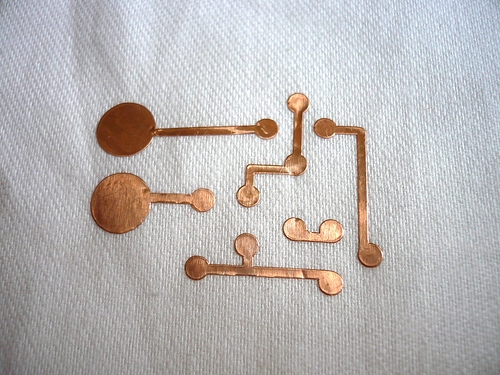
- Cutting. Pen Force as 80 gf and speed is set to 1cm/s (lowest).


- Weeding. You can use a knife to support the separation. Stick a wide piece of masking tape on front side to transfer the foil from its backing and still keep it in place. Then stick it to a backing fabric (in the image below, the fabric is non-stretchy white cotton). Press the copper bits so that the circuit adheres to the fabric.
The 3M 1126 conductive adhesive tape is pressure-set. This means that it sticks once you press it. To make circuits stick to your base, push the copper all over as evenly as you can. You can keep the masking tape on the circuit to protect it while pressing it.
Remove the protective masking tape by peeling it off at as sharp an angle as possible, as not to rip up any of the traces. If the copper is lifting as you peel off the masking tape, push the masking tape back down and press the lifting area some more.
When weeding do not try to keep the excess foil as one piece of copper, instead cut it away as often as possible.


- Solder components to copper foil.


eTextiles
Jie Qi's Vinylcut Fabduino
Here is a link to Jie Qi's Final Project: I/O paperHere is a link to Jie Qi's Images
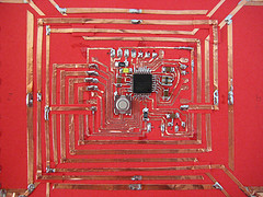
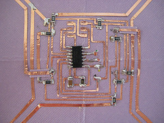
Simon de Bakker's Instruction
Flexible Circuit Tutorial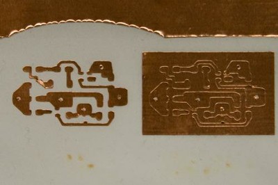
Nadya Peek
Instructable on vinyl cutting copper foil circuits

Hannah Perner-Wilson's Vinylcut Tilt Sensor


Copper Foils
- Cutronic Foil for PCBs
-
3M 1126 Copper Foil with Conductive Adhesive Tape
- TAPE COPPER FOIL 152.4MMX32.9M
- 3M #1126 copper tape with conductive adhesive 6"x 36 yds @$225.18/roll from Budnick Converting
- Cutronic Foil
Sources: How to Get What You Want
Nadya Peek
Paper Speaker
Paper Speaker from High-Low
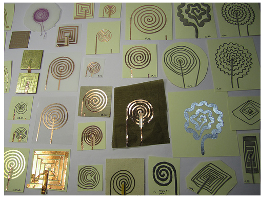 Hi-Low tech's paper speakers were inspired by Marcelo Coehlo's paper speaker and Vincent Leclerc's Accouphene textile speaker.
These speakers are made by running a 5-9V amplified sound signal through a very conductive coil in close proximity to a magnet. Unlike most speakers that have the wire coil wrapped cylindrically and placed around the magnet, here the coil is in the plane and directly adhered to the membrane that moves the air creating sound.
The coils can be made from a variety of conductive materials: copper tape, Conductive fabric, and conductive thread. A continuous spiral gives the best results.
Jean-Babtiste Labrune pointed out this planar coil calculator
Materials
- copper tape, conductive fabric, stainless steel thread
- some surface
- vinylcutter, scissors, paint brush, or sewing needle
- A vector file
- audio input jack
- amplifier circuit
Step-by-Step Instructions
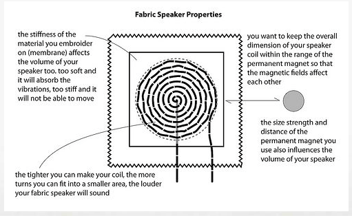
Image from Instructables
A speaker makes sound because an electromagnet is mounted to a membranewith a magnet close by. When an audio signal is connected to either end of the electromagnet (coil) a fluctuating magnetic field forms around the coil, repelling and attracting the membrane from the permanent magnet. These vibrations happen so fast that you cannot see them, but the membrane moves the air around it, which translates electrical frequencies into audible waves that you can hear.
- Create a coil shape. You can draw and scan or create in software.
- Cut out the coil
- Adhere coil to membrane
- For a quick first test of your speaker clip on two magnets one on either side of your coil, so that they hold each other in place. If you have a smaller magnet, then place this one on the front side, since the magnet is conductive it will otherwise short out your speaker's coils. You can also put a piece of fabric in between the magnet and the coil to isolate it. For your final design you will want to mount your magnet(s) in the center of the coil without having them directly connected to the membrane.
With aligator clips hook up your speaker to output of your source:


Images from Instructables - If you get a faint sound, go ahead and build your amplifier.
Amplifier Circuit
The Amplifier takes an electrical signal and makes the signal stronger, and in the end, louder. Because the signal is strengthened by an amplifier, you can play music through higher resistant speakers. This amplifier is a solid-state-hi-gain design and is intended to run through an 8 ohm speaker. The amplifier schematic was originally designed by Ed Vogel and Blind Lightnin' Pete from MAKE Magazine.The heart of the circuit is the operational amplifiers, or op amp. The op amp is an IC that produces an output voltage hundreds of thousands of times larger than the voltage difference between its input terminals:
Vout=AOL(V+-V-)
The LM386 is a popular audio amplifier chip that allows a user to amplify sound.
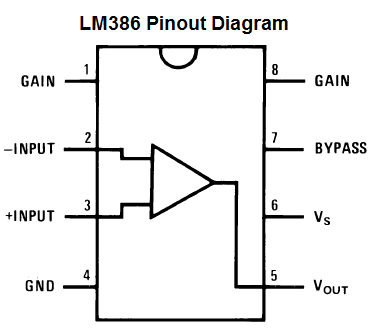
Image from www.learningaboutelectronics.com
| Pins | Description |
|---|---|
| 1 and 8: | The gain control of the amplifier. You can adjust the gain by connecting a variable resistor, like a potentiometer, a resistor and capacitor or just capacitor between these terminals. |
| 2 and 3: | The sound input signal terminals. These are the terminals where you place the sound which you want amplified. Terminal 2 is the -input and Terminal 3 is the +input. |
| 4: | GND (ground) |
| 5: | The output of the amplifier. This is the terminal in which the amplified sound signal comes out. |
| 6: | The terminal which receives the positive DC voltage so that the op amp can receive the power it needs to amplify signals. |
| 7: | The Bypass terminal. This pin is usually left open or is wired to ground. However, for better stability, you can add a 10µF capacitor to prevent oscillations in the op amp chip. |
The LM386 takes anywhere from 4-12 volts of DC voltage to operate.
Parts
- Breadboard—Jameco
- Wire—Jameco
- .01µF Capacitor—Jameco
- .047n Capacitor—Jameco
- 100µF Capacitor—Jameco
- 220µF Capacitor—jameco
- 10Ω Resistor—Jameco
- 25Ω Rheostat—Radioshack
- 5KΩ Potentiometer—Jameco
- LM386 —Jameco
- 8 Pin IC Socket—Jameco
- On/Off Switch—Jameco
- Battery Clip—Jameco
- 9 Volt Battery
- 3.5 mm Male Audio Jack—Cable Wholesale
- 6ft. 3.5 mm Male/Female Audio Ext Cord—Cable Wholesale
- 1/4" Knob—Jameco
- 2.5" x 4.5" Protoboard—RadioShack
Instructions
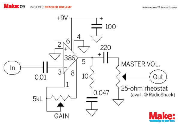
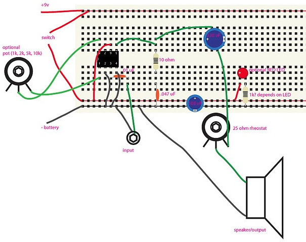
Image frommakerspace.com/
Image from Jameco
Full instructions
Breadboard the circuit first to test it.
- Solder wires on to the following components:
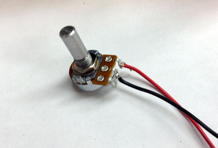
- Solder a red wire to the third lead of the 5K potentiometer and a black to the center lead:
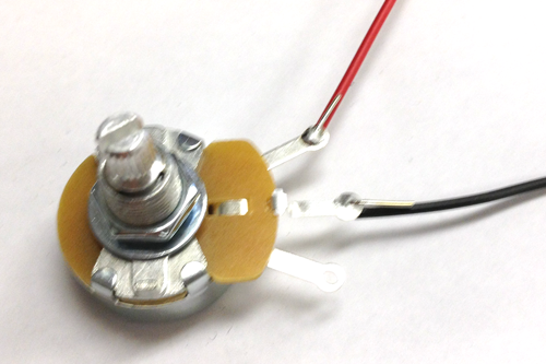
- Solder a red wire the the third lead of the Rheostat and a black wire to the center lead:
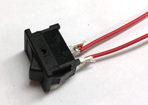
- Solder two wires to the leads of the switch:
- Solder a red wire to the first lead of the Audio Jack and a black wire to the second:
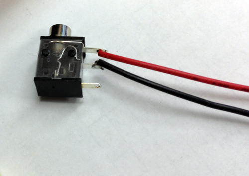
- Solder a red wire to the third lead of the 5K potentiometer and a black to the center lead:
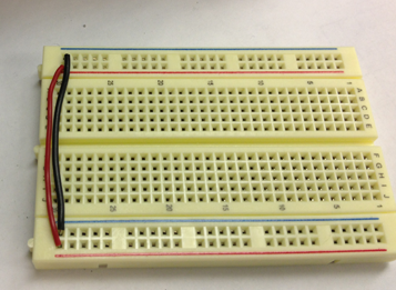
- Take two wires and connect power to power and ground to ground so that when you power the breadboard you will be able to use both power rails as power and ground:
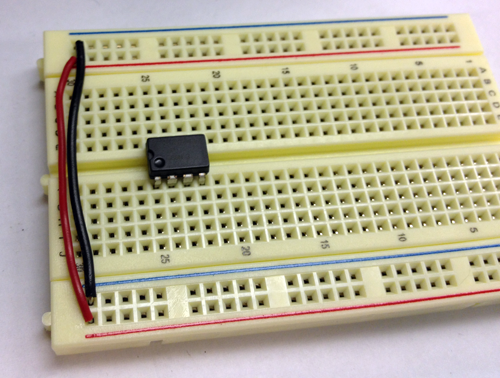
- Insert the LM386 chip over the gutter of your breadboard. Make sure that the circle is facing in the same direction as you see in the image. The pin closest to the circle is pin 1. On the same side are pins2-4. On the other side of the chip on a diagonal from pin 1 and across from pin 4 is pin 5. The pin at the top of the chip across from pin 1 is pin 8:
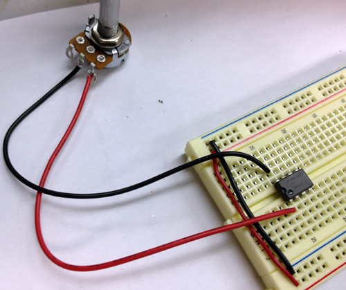
- Connect the red lead of the potentiometer to pin 1 and the black lead to pin 8. This potentiometer will control the volume:
- Use a wire to connect pin 2 to a GND rail:
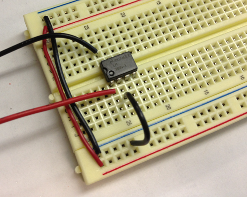
- Connect pin 3 to a row on the breadboard with the .01µF capacitor:
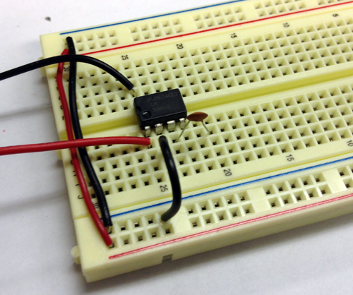
- Connect the other side of the capacitor to the red lead of the audio jack and the black lead to the GND rail
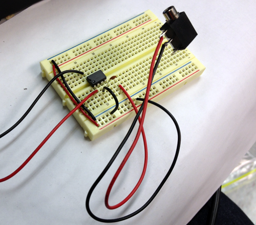
- Connect pin 4 to the GND rail:
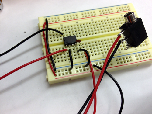
- Connect pin 5 to a row on the breadboard and that row to the 10ohm resistor. Connect the resistor to GND trough the 47n capacitor:
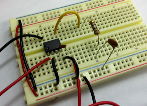
- Add the 220µF Capacitor (the long lead) to the same row that is connected to pin 5:
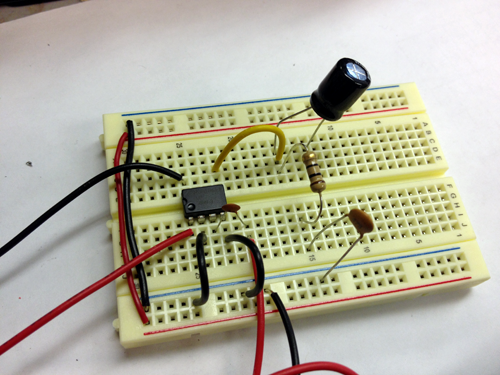
- Connect the red wire of Rheostat to the short lead of the 220µF Capacitor and the black wire to a row on the breadboard:
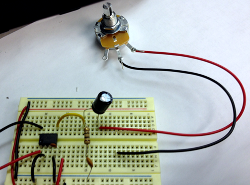
- Connect a red wire (later this will connect to your paper speaker) to the black wire of the Rheostat and a black wire (later connected to your paper speaker) to the GND rail:
Connect Power and GND through the 100µF capacitor:
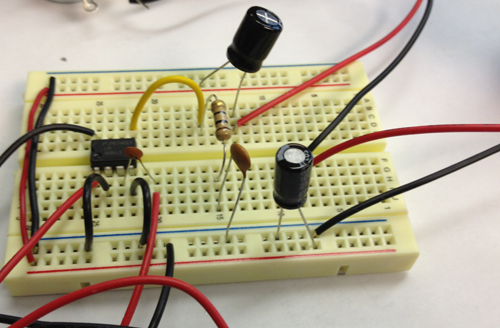
- Remove the red wire that connects power to power:
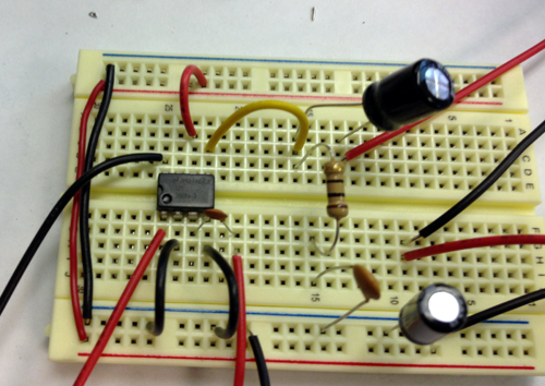
- Connect the two wires of the switch to the power rails
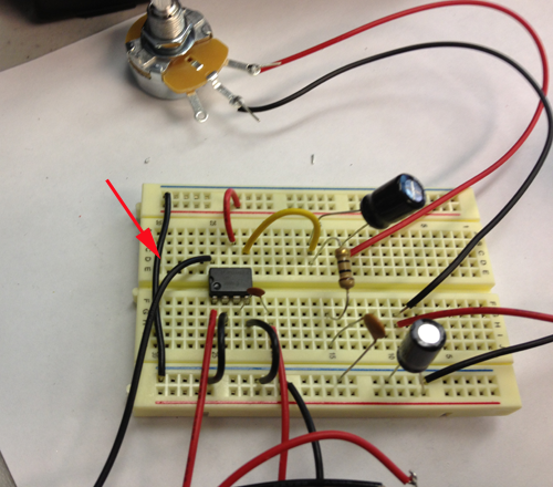
- Connect the 9V battery connector to the board:
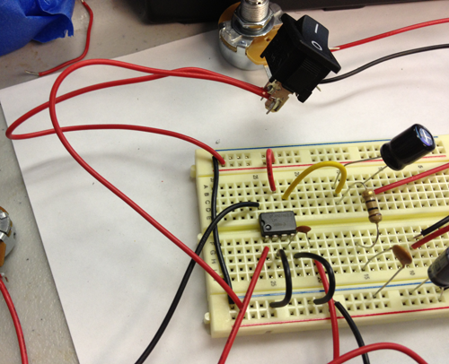
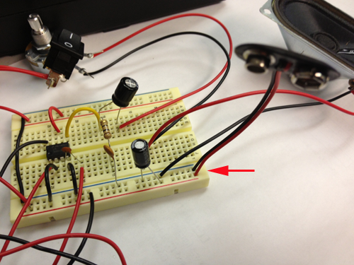
- Attach the battery, and connect an iphone to the circuit to test:
Puzzles and Maps
Use the Vinyl Cutter to cut out countries and continents. This exercise could reinforce country borders and familiarize students with geography.
Have students identify countries and add the names in a vector program. Cut out the vinyl shapes and have students recreate maps.
Use color for data
In the vector shapes below the yellow countries belong to Western Africa, the pink to Northern.
The pink form is Morocco The yellow form on the left is Mauritania
the left form is Niger
Inkscape
Inkscape is an open-source alternative to Illustrator. It runs on all major computer operating systems (Linux, Mac, and Windows), and can import and export to many major file formats. (SVG, AI, EPS, PDF, JPEG, GIF, PNG, etc.)
On Mac Inkscape runs under the X11 environment, Apple's spin on XFree86 Project's X Windows System, which is the foundation for Linux's GUI interface. X11 follows the same keystroke conventions as Windows.
Zoom Presets
Zoom 1:1—1 keyZoom 1:2—2 key
Zoom to selection—3 key
Zoom to drawing—4 key
Zoom to page—5 key
Zoom to page width—6 key
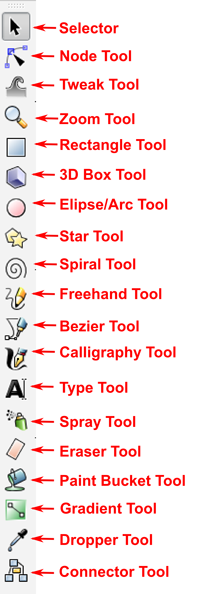
- Selector Tool: (S or Spacebar) Select and resize. With a second click, you can rotate and skew the selection.
- Node Tool: (N) The Node Tool lets you select nodes and adjust their handles to adjust the paths. Click and drag a section between nodes also adjusts the curve and brings out the nodes handles. Shift-C will let you adjust the node's handles independently of each other.
- Tweak Tool: (W) Push and pull paths and objects, shrink, roughen, shift the object's color, and blur the object.
- Zoom Tool: (Z) Zoom in and out (when holding the shift key) of your drawing area. You can also use the - (minus) and + (plus) keys to zoom.
- Rectangle Tool: (R) Create rectangles and squares. When you create your rectangle, they aren't quite paths yet. When a rectangle is selected, you'll see some handles at three of the corners. The squares let you resize your rectangle. The circle in the upper right-hand corner will split into two circles, but they will let you adjust the roundness of the rectangle's corners, to the point where your rectangle turns into an ellipse. To convert your rectangle into an editable path, go to the menu bar, select Path>then Object to Path. (Shift-Control-C)
- 3D Box Tool: (X) Create live 3D boxes in Inkscape, great for perspective drawing.
- Ellipse/Arc Tool: (E) Create ellipses. Dragging either handle on the right side inside the ellipse will maintain the fill within the parameter of the object up to the two circle handles. Dragging either of the circle handles outside of the ellipse will cause the ellipse's fill to cut straight into the center, like a pie chart. Just like the Rectangle Tool, your ellipse/arc is not a path yet. To convert it into a path, go to the menu bar, select Path, then Object to Path. (Shift-Control-C)
- Star Tool: (*) Creates objects that can be formed into stars or polygons. You'll find two handles on your newly created objects, one to adjust the points, the other to adjust the inside corners. The settings, under the menu bar, let you change the number of corners, the roundness of the corners, and there's a setting that let you turn your polygon into wacky abstractions.
- Spiral Tool: (i) There are two different handles on your new spiral. One handle to control the end in the inside of the spiral, and the other for the end on the outside.
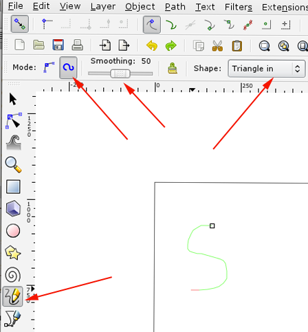
- Freehand Tool: (P) TCreate editable paths.
- Bezier Tool: (b) For creating bezier curves and straight lines. You have to click and drag to pull out a node's handle.
- Calligraphy Tool: (C) Create lines with varying widths. The end result isn't a skeletal stroke, but a newly created object with just a fill.
- Text Tool: (T) Click in a spot and start typing or click and drag to create a text box.
- Spray Tool: (A) Duplicates the last selected object in clusters as you drag your cursor across the canvas. The Spray Tool also has options that scatter and rotate your duplicates.
- Eraser Tool: (E) Works in one of two ways, either it'll create a temporary path that will delete any object beneath it. Or the Eraser Tool will create a new object, much like the Calligraphy Tool, and with the new object, use it to cut into the object under it.
- Paint Bucket Tool: (U) Floods areas with color. The Paint Bucket Tool can also be applied to vector objects, creating duplicates with a different color.
- Gradient Tool: (G) Apply gradients to your objects. Based on the type of gradient your using, you'll find some handles. You can use the handles to position where you want you color to begin. The handles can also be used, when you select one of them, to let you determine what color you want to use in that end of the gradient and the transparency with the Fill and Stroke Palette.
- Dropper Tool: (D) Pick-up color anywhere in your canvas. If you have another object selected while using the Dropper Tool, it'll change the fill to that color. The Dropper tool can't pick up the stroke color
- Connector Tool: (O) This tool is great for people who create diagrams. Basically the Connector Tool's purpose is to let you create lines that connect to your objects. Once those lines are created, they'll remain attached to your objects. If you have two squares linked together, and you choose to move one of them, the line will stretch/squash, and follow your square.
Spiro is a tool that is designed to be a stroke or curve.
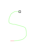
- The Spiro Path tool. This tool that will automatically convert any path you create to be a better and orderly path. There are three kinds of items that you can use to create a Spiro Path. The Triangle, Ellipse, and From Clipboard. Select Noneif you don't want to use a shape and just want to make a line. Using just the line tool, you can easily create your own style of floral design or swirly curl.
- Path Effects
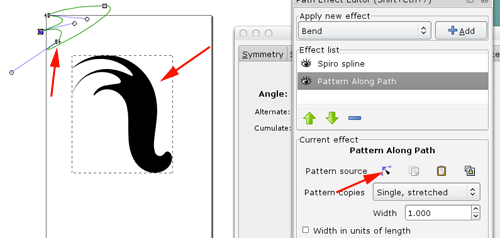
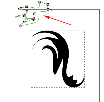
The Spiro Path uses two kinds of path effects, Spiro Spline and Pattern Along Path. Pattern Along Path gives you the opportunity to cut shapes, and paste them so that you can edit it as you like to get the shape you want. Note that the Spiro Path has limitations, which sometimes makes the path broken when using edit on canvas. Undo to fix it. When you select Pattern Along Path the pattern that you can modify will be found in the upper left corner of the page. Add points, modify the closed form and see how the flourish cha - Create Tiled Clones
This tool is useful for creating a pattern or forming the composition of the clones of your Spiro Path. There are several types of symmetry you can use when making clones. Using the few Spiro Paths you can create good designs with this tool.
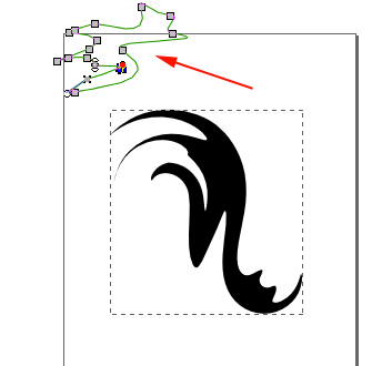
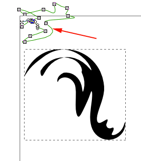
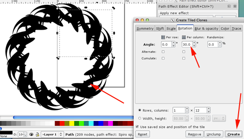
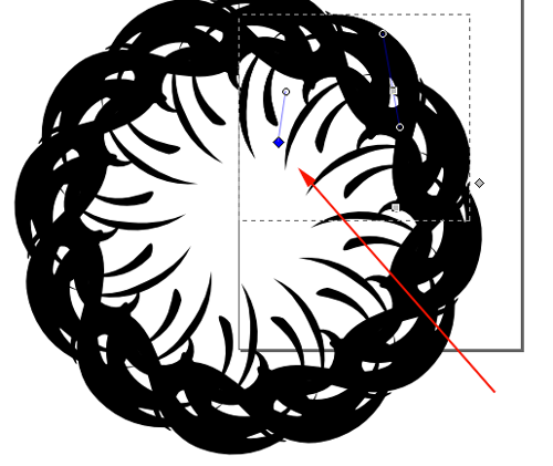
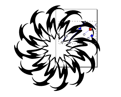
Source:chrishilbig.com
http://www.smashingapps.com/2013/02/11/useful-tutorials-for-creating-vector-graphic-using-free-software-inkscape.html
Here's another appraoch:
- Find an svg on the internet and import into Inkscape.
- Reduce the size and rotate 45°
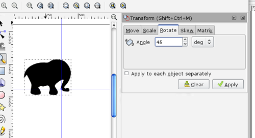
- Duplicate (CTRL+D), move
and flip horizontally:
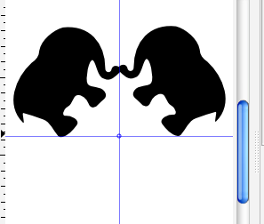
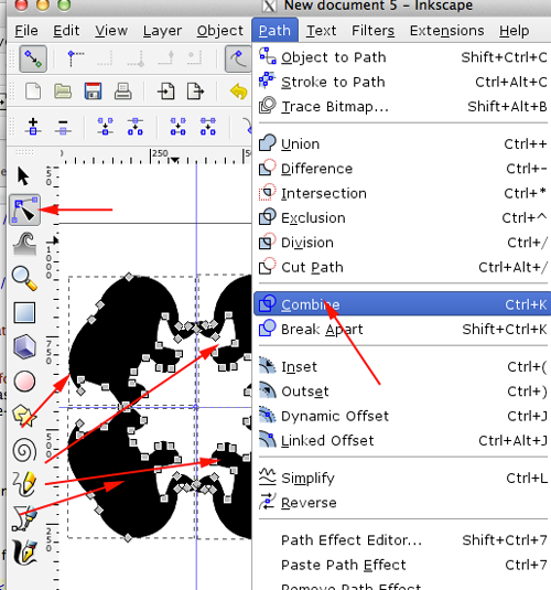
- Select both images and
duplicate again. Move the duplicated images below the fold and flip vertically:
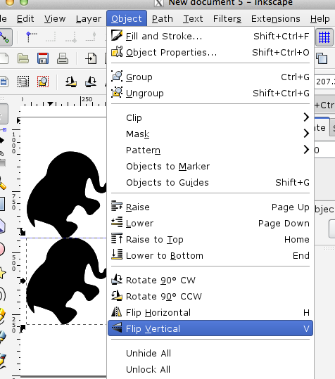
- Select all 4 paths and under the
Path menu select Combine
Laptop stickers
Vectorized Portraits
Source:Fab Lab San Diegoand Champaign-Urbana Community Fab Lab
Objective: To create vinyl decals with the personalized vector images. Vectors are made up of lines and angles that are attached to end points, or nodes.
- Start with preferably a high resolution image of the face you want to use

- Delete the background

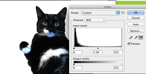
- Adjust the levels
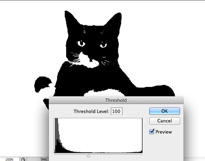
- Select Image>Adjustments>Threshold to reduce the colors to black and white.
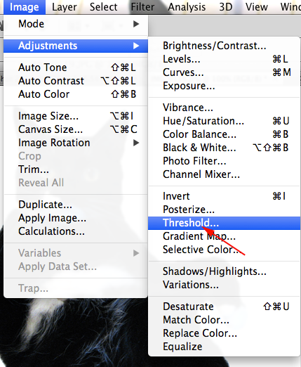
- I adjusted my image to 100
- Save the image

- Simplify if you need to:

- For the cutter software on Windows you need a .jpg or a .bmp file. On Mac you will use Illustrator with a plug in.
- If you want to create an svg too open a vector program like Inkscape.
- Open the image in the program

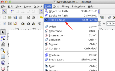
- Select Path>Trace Bitmap
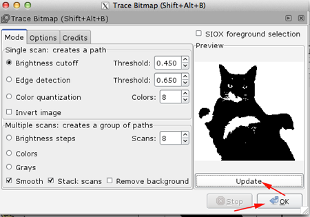
- Click Update and OK to convert the bitmap to vector
- Save as an .eps file
- Load the electronic Cutter.
Make sure the cutter is off
- Unhinge the latch in the back:

- Load a roll on top of the feeder rollers

-
pull material through to make sure it does not catch on the lip of the machine:

- Position the little wheels to the edge of your material then close the latch

- Adjust your options. Select our feed style. Select 60 gf for light material (paper, thin vinyl) or 120 gf for glossy heavy duty vinyl

- Convert your graphic in CutStudio
Import your graphic
- Select object then click Object>Image Outline

- Click on Extract Contour Lines (you may need to adjust the image density )

- Once you click the button you should see blue lines.
- Select Cutting

- Select File>Print. Let it auto-detect the margins.
Roland Images from Champaign-Urbana Community Fab Lab


