Importing Files
Extruding .svg files
- Make sure that all your vertex points are joined in either Inkscape or Illustrator.
- Save as an svg file
- Open Blender
- Delete the default cube (X)
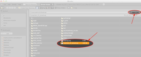
- Select File>Import>Scalable Vector Graphics (.svg)
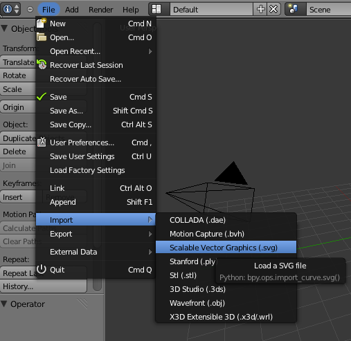
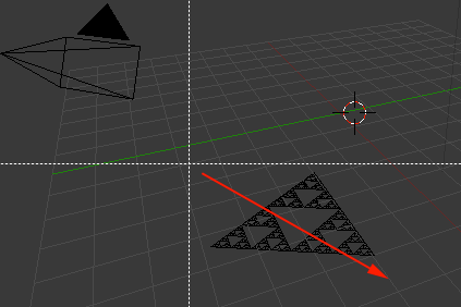
- Navigate to your file and import it
- Press B to boundary select and select the form
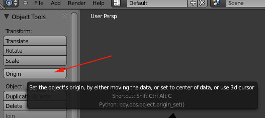
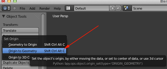
- Change the Origin by clicking on the Origin button in the tool shelf and select Origin to Geometry. or press SHIFT+CTRL+ALT+C
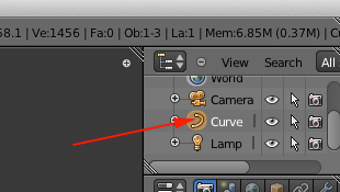
- Click on the Curve in the Scene Window
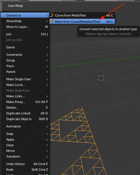
- Select Object>Convert and convert the curve to a mesh
- Press Tab to switch to Edit Mode
- Press B to boundary select and select the form
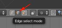
- Select Edge Select Mode to make sure edges are selected
- Press E to extrude and drag the mouse p
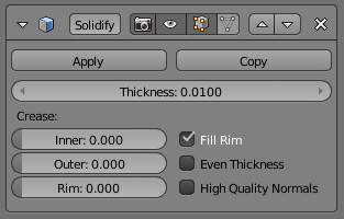
- Back in Object mode add Modifier>Solidify
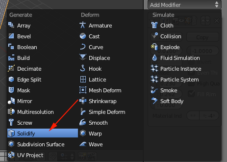
The Solidify Modeler is used to non-destructively add thickness to thin meshes (similar to shell modifiers in other applications). Solidify allows you to model a simple thin mesh surface, and have a solid thickness automatically extruded by the modifier.
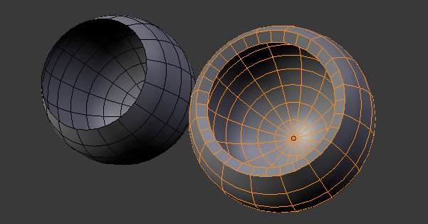
In edition to extrusion, solidify also has options intended for usage with subdivision surfaces, automatically adding sharp creases to extruded edges and rims.
So you can:
- Model walls from floor plans with consistent thickness
- Model hollow objects such as cups or bottles
- Select File>Export>STL(.stl)
Vertex Editing
| Remove Vertex Point |
- Alt MKEY to merge the points to the center of the points or to the cursor location
- To merge to a selected point first select the point press Shift SKEY and select Cursor > Selection then select all the points you wish to merge and Alt MKEY to Cursor.
|
| Add Vertex Point |
- Select the edge you want to add a vertex to, and press w>Subdivide. If you want more than one vertex, use Subdivide Multi.
- Select one vertex point, then
hold CTRL key and click the left button of your mouse.
- Edit mode, Select Vertex, Press E to extrude only vertex.
- Use the knife tool:
Enter edit mode, select edges to operate on, press k key. Choose one of the knife tools, draw cut, press enter to finish.
|
Spin Mesh Modeling Tool
http://cgcookie.com/blender/2012/01/11/blender-feature-using-the-spin-tool/
loft or lathe around a circular point
consistent around a central axis
Dupli-duplicates instead of extrude
Helpful for reating cylindrical shape.
front view then Num 5
add mesh object as basis for spin. Add a plane.
With mesh selected click on spin in the tool shelf (9 times with max rotation of 90°)incremental steps for extrusions. F6 after using the tool can edit the incremental steps
duplication instead of extrude keeps the steps separate
° can change the max angle
Dupli option-adjust center Point
Position 3d cursor than Spin
Default axis is perpendicular to view Port
Start with a vertex and draw a shape than spin (360,
select everything
w
remove doubles
solidify to add thickness
