July 23, 2015, 9am - 4pm
A one day workshop to become familiar with AutoCAD and the 3D Modeling Curriculum.
3D printing in education
30 minutes:
- Divide up into teams of 3.
- Take 8 minutes to write down as many polarizing statements about 3D printing and education that you can think of. You don't have to agree with your statements.
- Pick two statements. (one will be your back up and you can use it in case another group uses your first choice).
- Teams go around the room and one at a time, read a statement and people move from one side of the room to the other according to agreement. The center is neutral. People on all sides voice their opinion. See if the crowds move.
What is 3D Printing and Why Teach It
Basic Types
3D PrintersStereolithography (SLA):
A process that works by curing and solidifying successive layers of liquid photopolymer resin using an ultraviolet laser.Industrial:
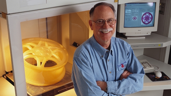
image from:Industry Week
Desktop:
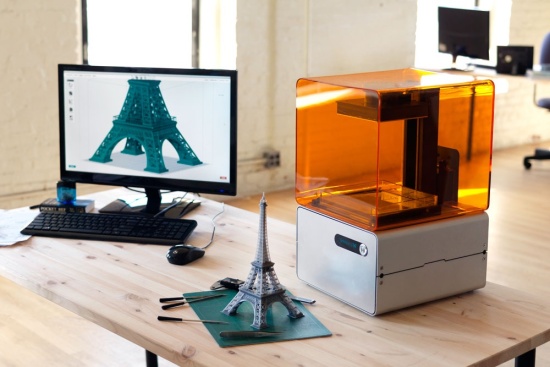
image from:www.3ders.org
Selective Laser Sintering (SLS):
Similar to SLA, but instead of using liquid resin, powdered material is used. The material can be anything from nylon, ceramics, glass, aluminum, to steel or silver. The laser is traced across a powder bed of tightly compacted powdered material, according to the 3D data fed to the machine, in the X-Y axes. As the laser interacts with the surface of the powdered material it sinters, or fuses, the particles to each other forming a solid.Industrial:
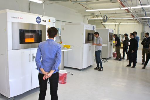
image from:nyc3dp.com
Desktop:
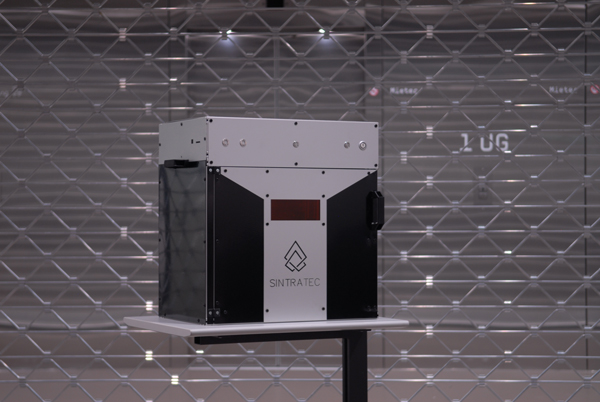
image from:3dprint.com
Fused Deposition Modeling (FDM)→Fused Filament Fabrication (FFF):
This process uses certain melted thermoplastic materials that are joined together to form a shape. As the material hardens, a 3D object is formed.Industrial:
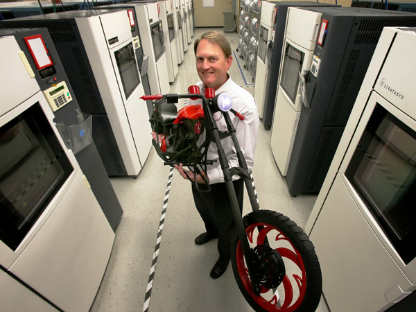
image from:www.3dnatives.com
Desktop:
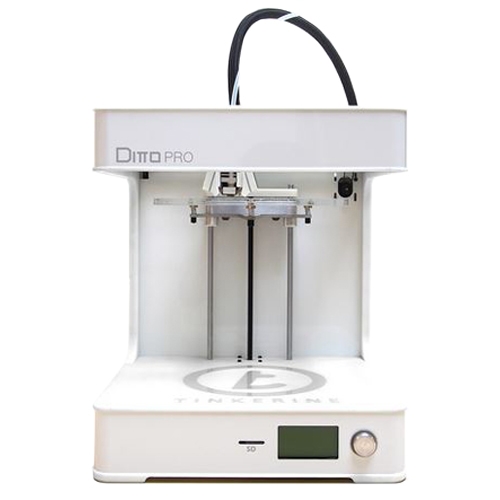
image from:Tinkerine
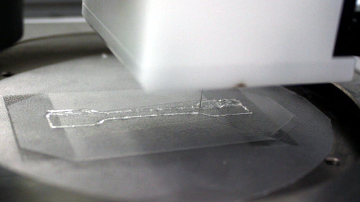
FFF Demonstration
Applications
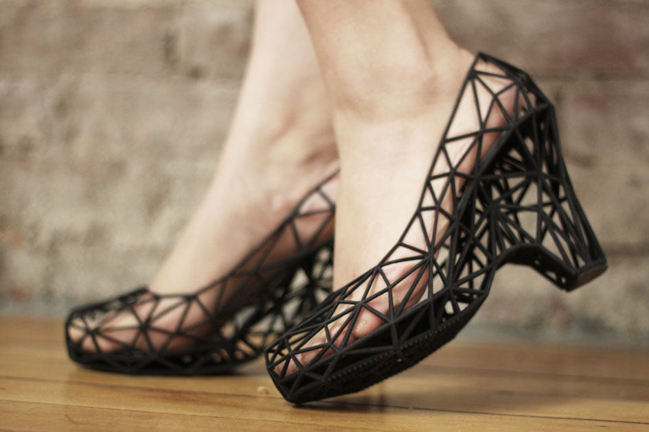
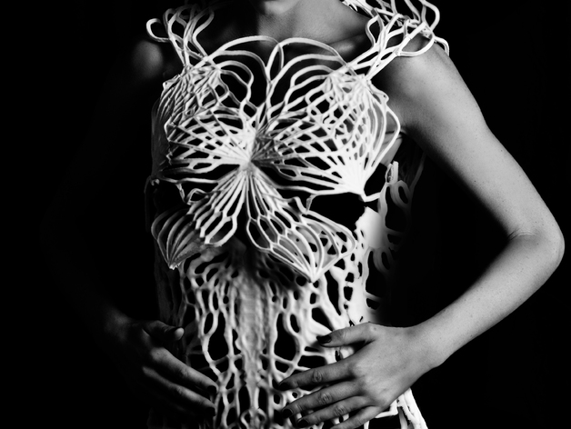
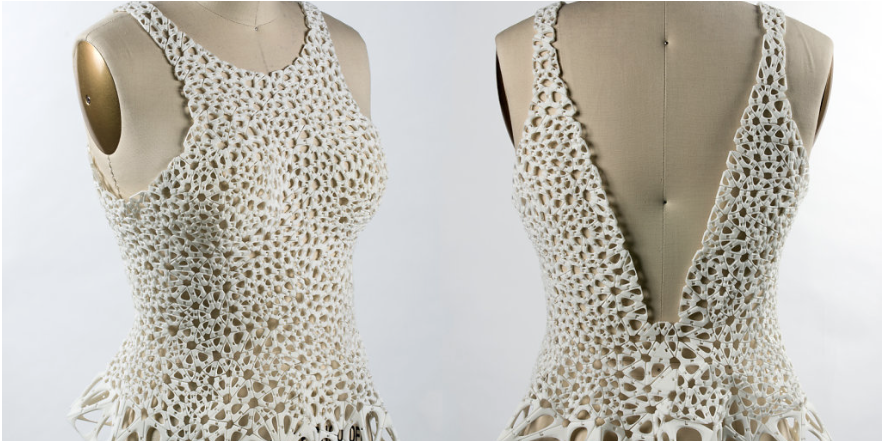
3DX Fashion
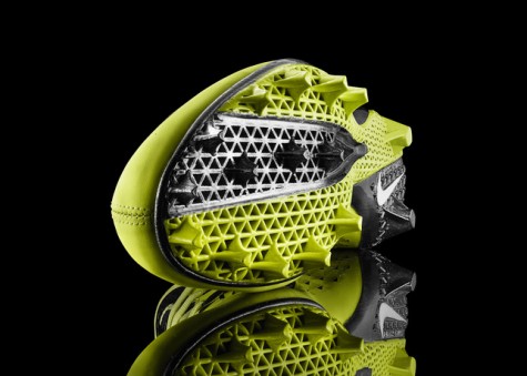
Footwear and apparel company Nike believes 3D printing technology can speed up athletic performance
Image from
3DX Food
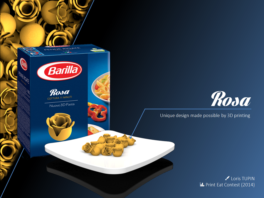
Loris Tupin, a French industrial designer from Maxilly sur Léman, presented the biodynamic model of a flower that, from a bud, changes into a rose during cooking
Image from 3dprintingindustry.com
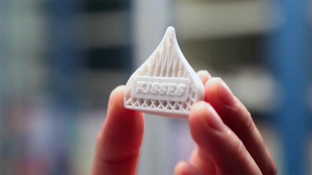
Hershey Unveils 3-D Chocolate Candy Printing Exhibit in Partnership with 3D Systems
Image from 3dprintingindustry.com
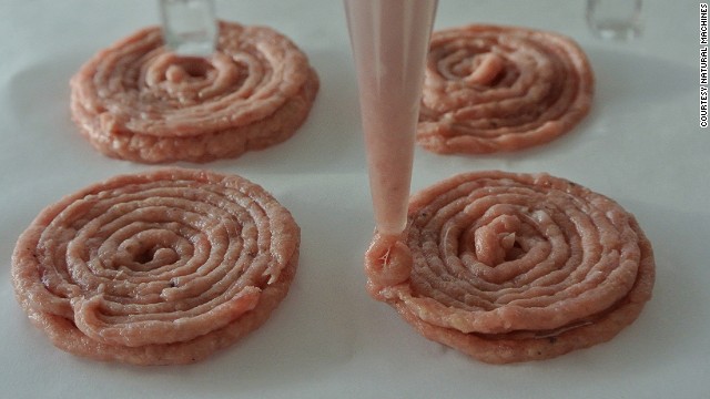
Ingredients are loaded into stainless steel capsules. Load them with beef to print out mini burgers.
Image from cnn.com
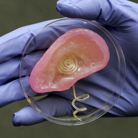
3DX Health and Medicine
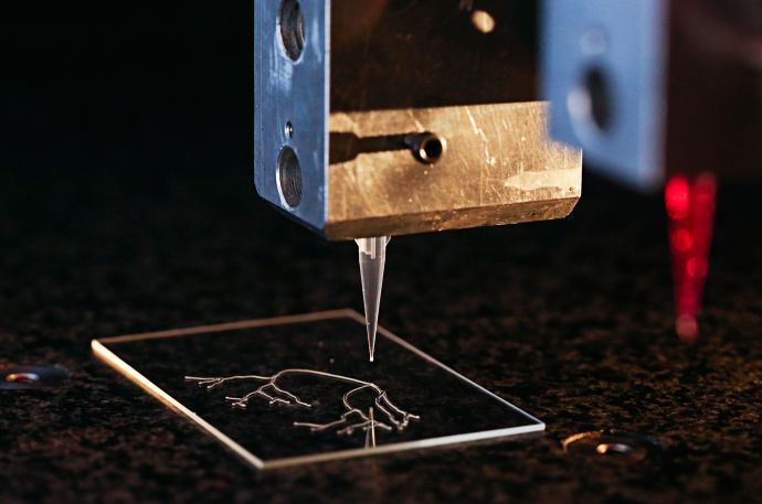
A 3-D printer used by researchers at Harvard University's Wyss Institute creates a model vascular network.
Image from LORI K. SANDERS
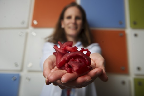
Pediatric cardiologist Laura Olivieri of Children's National Medical Center displays a heart model created by a 3-D printer. (Amanda Voisard/For The Washington Post)
Image from Washington Post
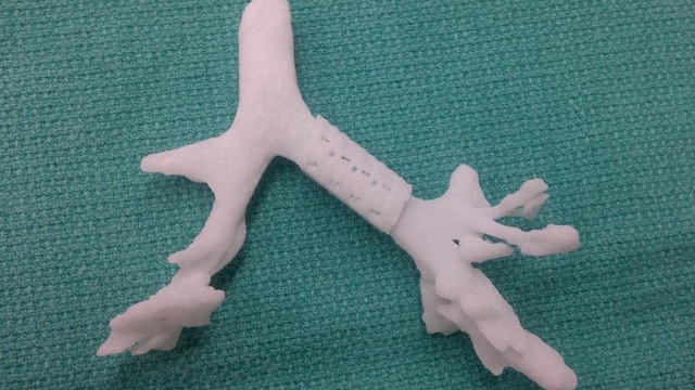
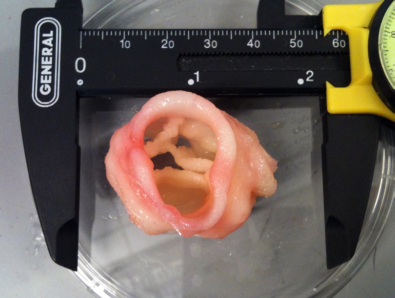
Bioresorbable Airway Splint Created with a Three-Dimensional Printer
Image from The New England Journal of Medicine
3DX Data Visualization
3DX Design
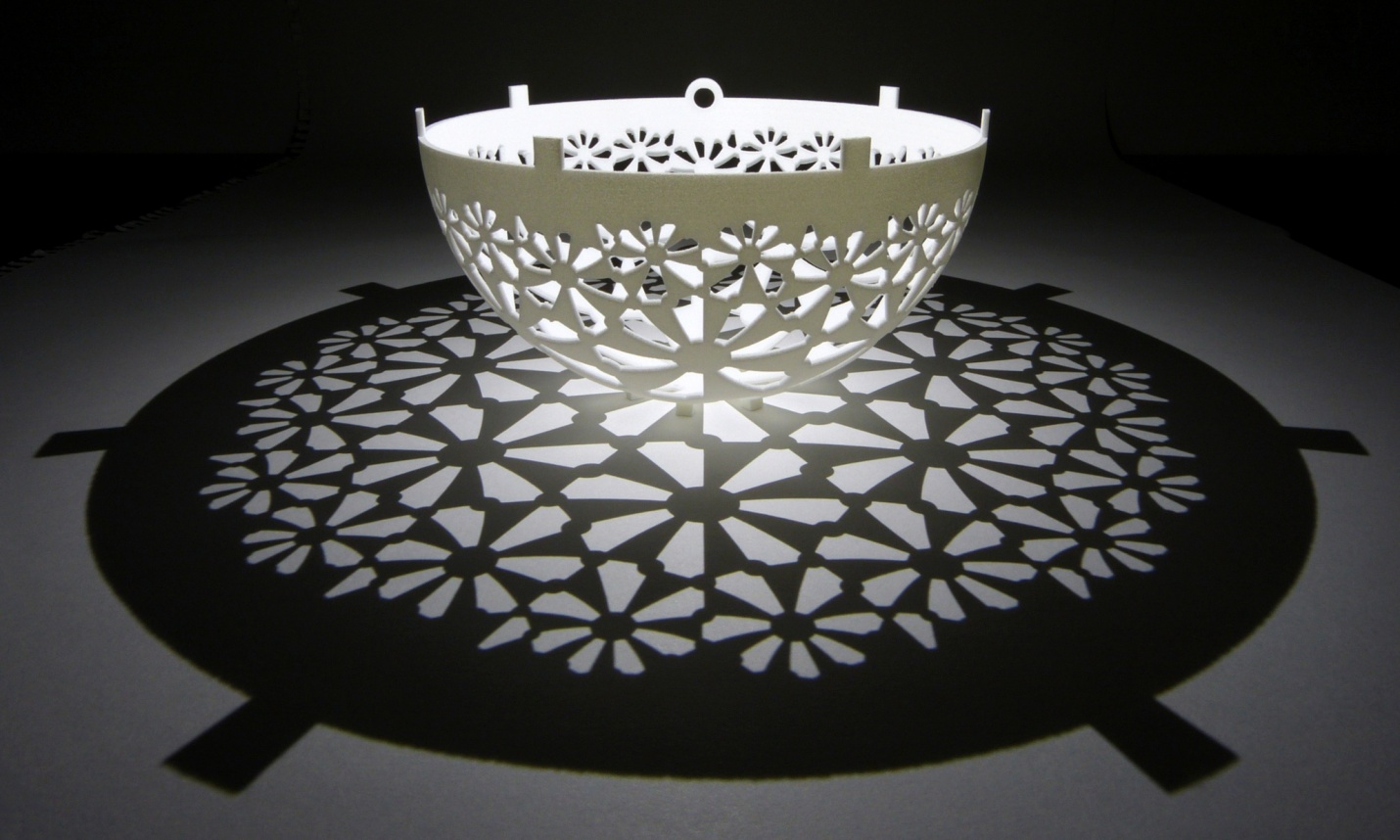
Henry Segerman and Saul Schleimer cast astounding shadows and designs from their designs.
Image from 3dprintingindustry.com
Why we should teach it.
As teachers, we want learning environments and activities that engage and challenge our students. We want to tap into their curiosity, inspire them to see connections between ideas and information and have them use their understanding to creatively problem solve with independence. Our objective is to instill a love of learning, so that they can think critically, communicate effectively, persevere, be intrinsically motivated, be responsible for their own learning outcomes, and find joy in the process.Uses:
- Allows for data visualization.
- Provides tactile feedback.
- Is another means of communication.
- Invites one into the realm of the D.I.Y. ethic.
- Engages students in STEM based projects.
What students get from being involved with 3D Printing:
- Gain understanding of Additive Manufacturing
- Gain experience with Computer Aided Design and Drafting (CADD)
- Participate in process of Rapid Prototyping (RP).
- Participate in process of Reverse Engineering.
- Participate in process of Brainstorming and ideation
- Establish personal Workflows
What kind of tools are available?
- Autodesk Suite (AutoCAD, 360 Fusion, Maya, Inventor)
- Blender
- 123D Design
- Meshmixer
- Tinkercad
- OpenSCAD
- SketchUp
- Morphi
- 3DSlash
Why are we focusing on AutoCAD?
AutoCAD, an application for 2D and 3D computer-aided design (CAD) and drafting, is Autodesk's flagship product and has been available since 1982. As of 2015, AutoCAD is in its thirtieth generation, and collectively with all its variants, continues to be the most widely used CAD program throughout most of the world.
AutoCAD is used across a wide range of industries, by architects, project managers, engineers, graphic designers, and other professionals. AutoCAD allows you to design with precision, use the commandline to speed up design time, add dimensions and constraints and use all basic modeling techniques. You can design as you go, make changes at will, and delete/modify entire sections without effecting the overall process. Once you've learned how to use AutoCAD, you will know what to look for in other CAD programs and learning them will be much easier.
Installation Help
Modeling Basics
Modeling Basics
List basic modeling techniques:
- Constructing primitives
- Drawing profiles
- Revolve
- Sweep
- Extrude
- Loft
- Shell
- Slice
- Union
- Intersect
- Subtract
- Fillet
- Chamfer
An Introduction to AutoCAD
An Introduction
Set Up
- Launch AutoCAD.
- Select the acad template:
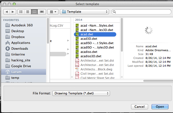
- Make sure CommandLine is visible. If not open it under the Windows menu.
- You need to change the units of the drawing to millimeters.
TypeUN
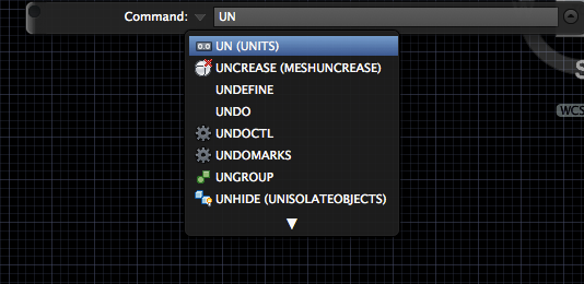
- Set the units to millimeters:
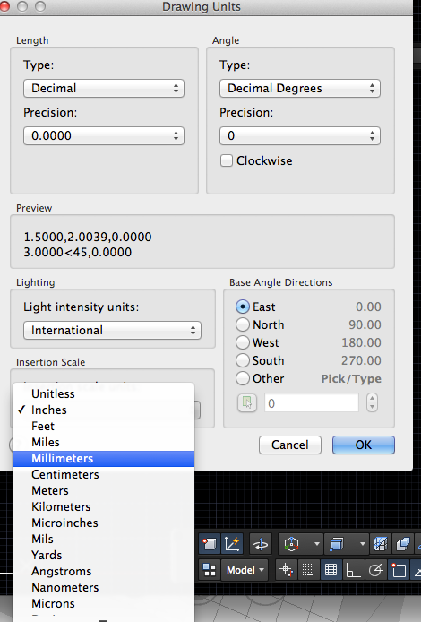
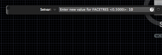
- If you will be 3D printing the model you need to create a higher resolution mesh. Type
facetres

- Set the facetres to 10:
- If you want to keep a record of the profiles turn DELOBJ to 0. This system variable controls whether geometry used to create other objects is retained or deleted.
Type:0 All defining geometry is retained. 1 Deletes profile curves, including those used with the EXTRUDE, SWEEP, REVOLVE, and LOFT commands. Removes all defining geometry for CONVTOSOLID, CONVTOSURFACE, CONVTONURBS, and CONVTOMESH commands. Cross sections used with the LOFT command are also deleted. 2 Deletes all defining geometry, including paths and guide curves used with the SWEEP and LOFT commands. 3 Deletes all defining geometry, including paths and guide curves used with the SWEEP and LOFT commands if the action results in a solid object. Removes all defining geometry for CONVTOSOLID, CONVTOSURFACE, CONVTONURBS, and CONVTOMESH commands. This setting also applies to options in commands such as PEDIT and SPLINE for converting between splines and spline-fit polylines. The range of non-zero values is present to maintain AutoCAD compatibility. -1 Displays prompts to delete profile curves, including those used with the EXTRUDE, SWEEP, REVOLVE, and LOFT commands. Prompts to remove cross sections used with the LOFT command. The original geometry for CONVTOSOLID, CONVTOSURFACE, and CONVTOMESH commands is removed without prompting. -2 Displays prompts to delete all defining geometry, including paths and guide curves used with the SWEEP and LOFT commands. The original geometry for CONVTOSOLID, CONVTOSURFACE, and CONTOMESH commands is removed without prompting. -3 Displays prompts to delete all defining geometry if the resulting entities are a surface of any type. Deletes all original geometry resulting in a solid entity, original geometry for CONVTOSOLID, CONVTOSURFACE, CONVTONURBS, and CONVTOMESH commands is removed without prompting. DELOBJ
Drawing

absolute
relative
polar coordinates
- rectangle
- circle (tan, tan radius)
- polygon
Modifying
- TRIM
TR
- EXTEND
EX
-
OFFSET
OFFSET
-
STRETCH
STR
-
MIRROR
MIRROR
-
ROTATE
ROT
Editing
- COPY
CO
- MOVE
M
- PEDITEdits polylines, objects to be joined to polylines, and related objects. Common uses for PEDIT include joining 2D polylines, and converting lines and arcs into 2D polylines.
PE
-
POLYLINE (Pline)Creates a 2D polyline, a single object that is composed of line and arc segments.
PL
- REGIONRegions are solid 2D shapes. You can combine existing regions into a single, complex region.
REG
Regions can be used for combining simple objects into more complex ones with Boolean operations. - EXPLODEYou can convert a compound object, such as a polyline, dimension, hatch, or block reference, into individual elements. For example, exploding a polyline breaks it down to simple lines and arcs.
EXP
2D to 3D
-
presspullDynamically modifies objects by extrusion and offset.
PRESSPULL
-
EXTRUDECreates a 3D solid or surface by extending a 2D or 3D curve. Extrusions can extend in the Z direction or be set to taper or follow a path. You can extrude an open or closed object to create a 3D surface or solid.
EXT
- REVOLVECreates a 3D solid or surface by sweeping an object around an axis.
REV
Open profiles create surfaces and closed profiles can create either a solid or a surface. The MOde option controls is a solid of surface is created. -
SWEEP Creates a 3D solid or surface by sweeping a 2D or 3D object or subobject along a path.
SWEEP
-
SHell
SOLIDEDIT:body:Sh
- OFFSETEDGE Creates a closed polyline or spline object that is offset at a specified distance from the edges of a selected planar face on a 3D solid or surface.
offsetEdge
Boolean Operations
- UNIONCombines two or more 3D solids, surfaces, or 2D regions into a single, composite 3D solid, surface, or region.
UNI
- INTERSECTCreates a 3D solid, surface, or 2D region from overlapping solids, surfaces, or regions.
INT
- SUBTRACT Creates as a new object by subtracting one overlapping region or 3D solid from another.
SUBTR
Primitives
- BOX
- CONE
- CYLINDER
- PYRAMID
- SPHERE
- TORUS
- WEDGE
- POLYSOLID
Afternoon Challenge
Afternoon Challenge
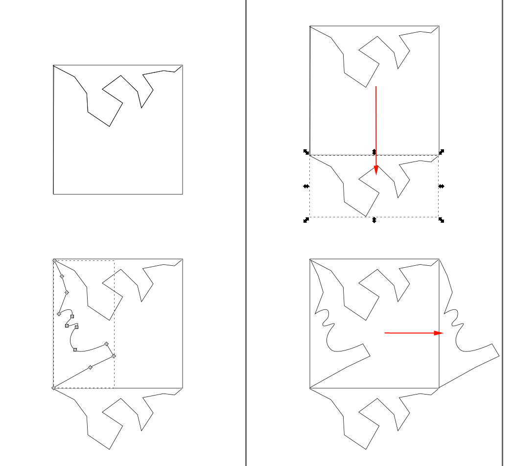
Create a tile for a tessellation.Tessellations are comprised of tiles that cover a plane with no gaps or overlaps.
Translation
Take a nibble from the top and translate it down.Take a nibble from the left and translate it to the right.
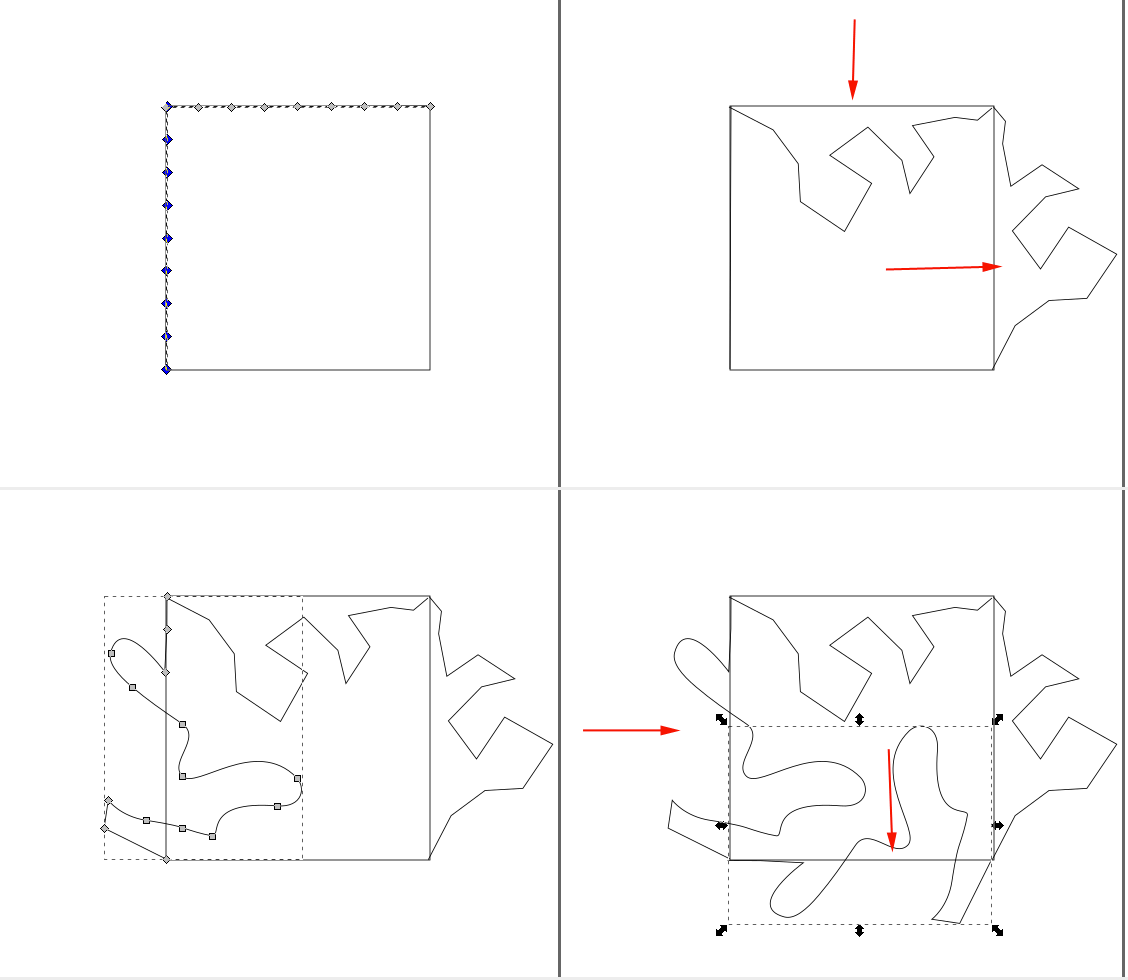
Rotation
Take a nibble from the top (constrain the nibble to the top half) and translate and rotate it CCW so that it fits along the right side.Take a nibble from the left and translate and rotate it CCW so that it fits along the bottom.
More challenging rotation
Start with a hexagon.Take a nibble from a side and translate and rotate it CCW so that it fits along the edge to the right.
Continue until all sides are covered
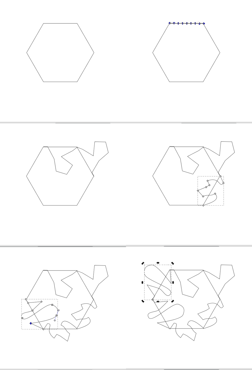 There is not one right way to do this project. It can be accomplished using a combination of commands. The goal is for you to break down the problem and use what might be the best series of commands to acheive your goal.
Once you have decided on the type of tile to construct and have created it, you'll need to create an offset. Why do you need an offset? A cylinder wwill not fit into a hole if they both have the same diameter. If you want a cylinder to fit snuggly into a hole make the diameter of the hole .4mm larger. If you want the cylinder to slide, make the hole at least .8mm larger. The offsets are known as tolerances and are determined by your printer. In order to create an offset, you'll need to have a continuous line or polyline.
You can try this exercise on your own, or you can use the following information to help you:
- Create a new document.
- Set up the drawing to be in millimeters and to increase the mesh resolution for 3D printing.
- Launch AutoCAD
- Select the acad template:

- Make sure CommandLine is visible. If not open it under the Windows menu.
- You need to change the units of the drawing to millimeters.
TypeUN

- Set the units to millimeters:

- If you will be 3D printing the model you need to create a higher resolution mesh. Type
facetres

- Set the facetres to 10:

- If you want to keep a record of the profiles turn DELOBJ to 0. This system variable controls whether geometry used to create other objects is retained or deleted.
- Select the type of tessellation you want to create.
Do you need to start with a square? A hexagon? You can draw the shape with lines (L) and relative positions or polar coordinates, or you could use a command like RECTANGLE or POLYGON. Consider starting with a shape that has a 30-60mm width. - You might want to divide the lines up so that you can align the nibbles precisely in their new locations.
If you started with the RECTANGLE or POLYGON command you won't be able to divide the lines until you explode the shape.
- EXPLODEYou can convert a compound object, such as a polyline, dimension, hatch, or block reference, into individual elements. For example, exploding a polyline breaks it down to simple lines and arcs.
EXP
- EXPLODE
- Once you have individual lines you can divide them. If you don't see the divisions you can use the DDPTYPE command in AutoCAD 2014 or the PTYPE command in AutoCAD 2015 to set the shape and size of the points.
- DIVIDE Creates evenly spaced point objects or blocks along the length or perimeter of an object.
DIV
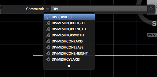
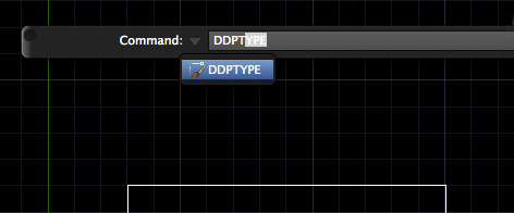
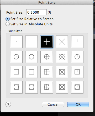
- DIVIDE
- You could use lines (L) or polylines (PL) to draw your nibble. The advantage of PL is that it is a continuous line which will be easier to copy.
If you use PLINE you can start your line at one of the divisions, then create lines and arcs. Don't close the shape, but do end it at another division point (Press RETURN to end the line).
- You will have to translate and possible rotate a copy of the nibble.
- Consider dividing the target line (where you want to align the copy to) to help you align the nibble correctly. This is particularly useful if you will be rotating the nibble.
- COPY
CO
- Use relative positioning (@x,y) to move the nibble down or over.
- ROTATE
RO
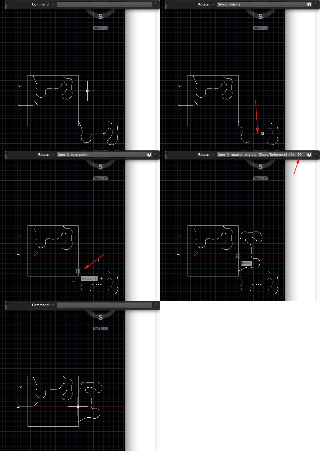
- You'll need to trim the shape.
- TRIM
TR
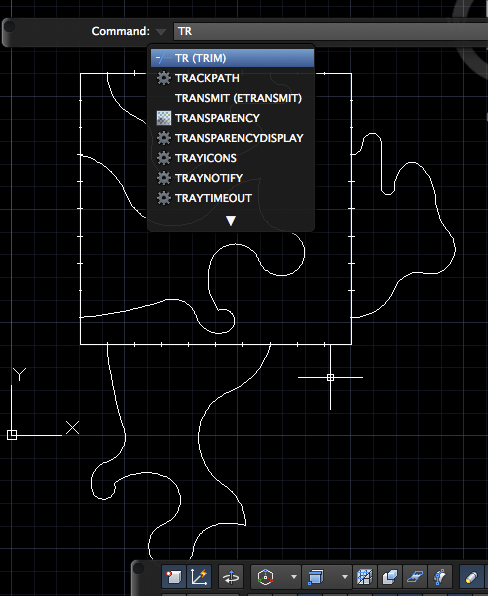
Select all your nibble shapes first and then press RETURN:
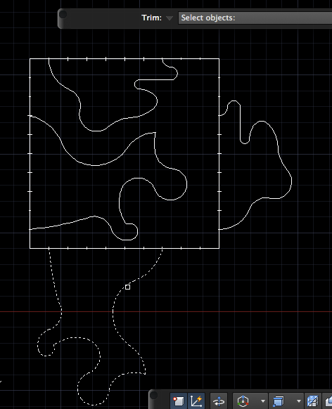 Click on parts of your square or hexagon:
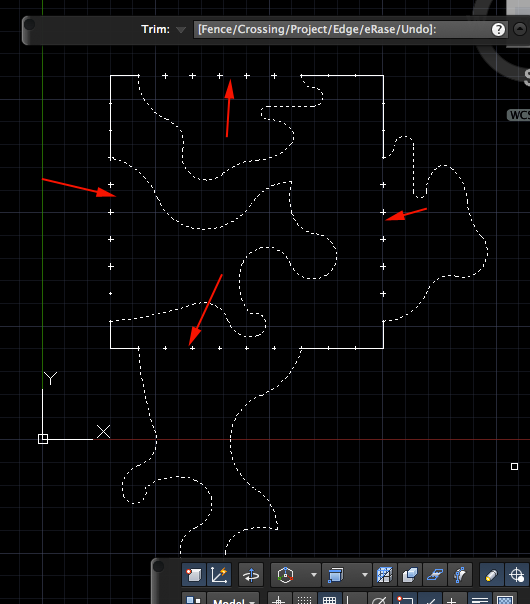
- TRIM
- Delete the points if they exist. Just select them and press the DELETE key:
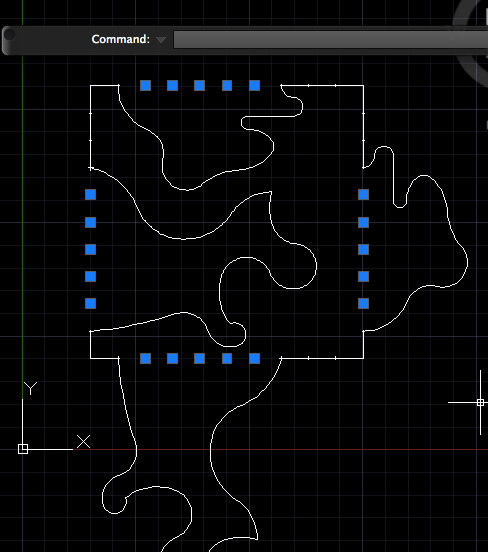
- You need to make your shape a continuous line.
- PEDIT Specify Multiple
PE
Select all the lines
Type Y and press RETURN
Press J for Join
Accept 0.000 as fuzz factor
Press RETURN until PEDIT command completes
- PEDIT
- You need to create a offset (make the shape slightly smaller). If you offset the outline by .2mm, your shape will be .4mm smaller (.2mm from each side), which is what you want.
- OFFSET
OFFSET
- Set the distance (.2mm)
- Click on the side you want the offset to be (remember, make the shape smaller, not larger)
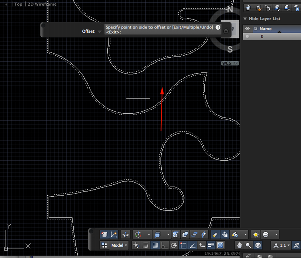
- Delete the larger shape.
- OFFSET
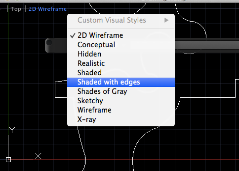
- You can add details. Convert your shapes to REGIONS. In order to see the REGIONS, change your view to shaded with edges
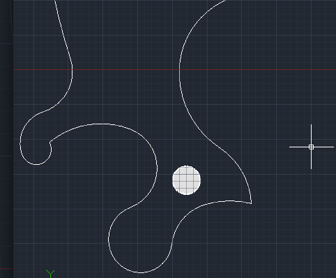
- If you added details use SUBTRACT to subtract the smaller shapes from the larger shapes. Select the REGION you want to keep, press RETURN, select the REGIONS you want to remove and then press RETURN.
- Extrude the shape by 2mm.
- Export the shape.
- EXPORT
EXP
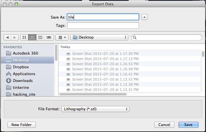
- Name the STL file:
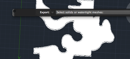
- Click on your tile when prompted to select solids or watertight meshes:
- EXPORT
