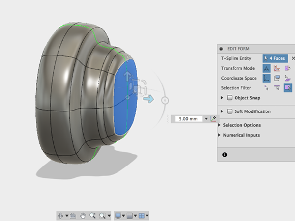
Fusion 360 Basics
Fusion 360™ is a cloud-based 3D CAD/CAM tool for product development that combines industrial and mechanical design, collaboration, and machining in a single package. Fusion 360 enables fast and easy exploration of design ideas with an integrated concept-to-production platform. Fusion 360 Gallery
Sign up for an Autodesk account and download and install Fusion360. Get Fusion 360 for education
Getting Your Feet Wet
Fusion 360 is a cloud-based CAD/CAM tool for collaborative product development.
1 Application Bar
| Data Panel | |
| File | |
| Save | |
| Undo/Redo |
3 Tool Bar
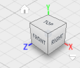
4 View Cube
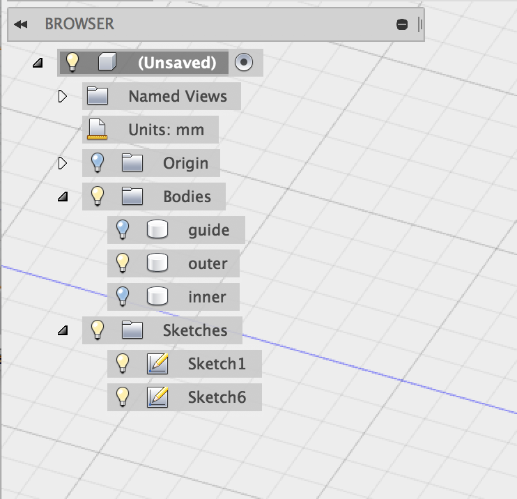
5 Browser
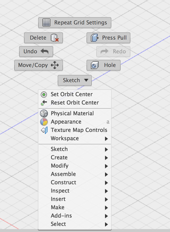
6 Canvas and marking menu
7 Timeline

8 Navigation

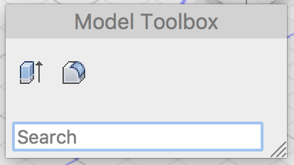
Making a box with a hole
- Open Fusion 360.
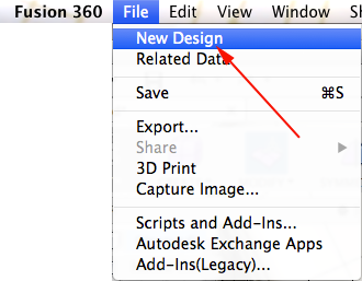
- Fusion 360 will open a new design. However if you are in a design and want to create another one, select File→New Design:
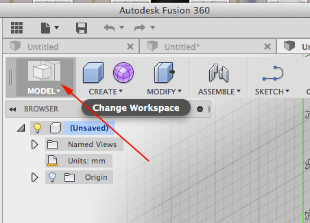
- Select Model mode:
- Click on Box:
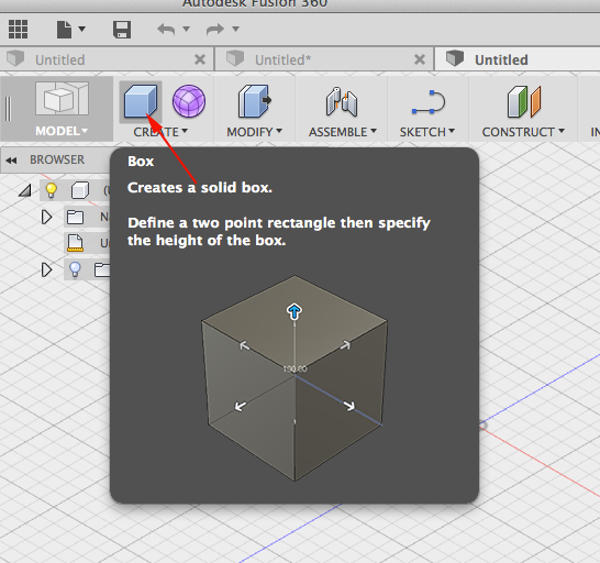
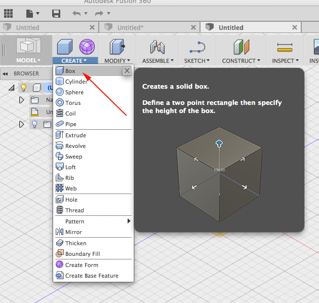
- Select Box from the pulldown menu:
- Select the ground plane by clicking on the blue red plane:

- Click on the center to start drawing.
- Enter a dimension in the field, press Tab and enter the other. Press tab once more and move the cursor into the different quadrants. click to accept parameters:
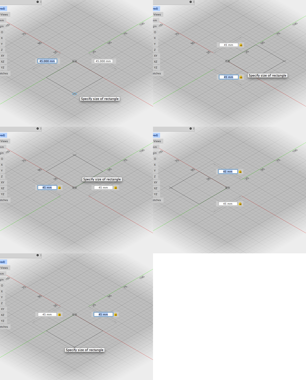
- Adjust height in the text entry field or in the box window:
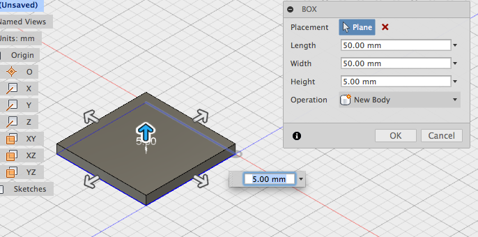
- Press ENTER or click OK to create the box
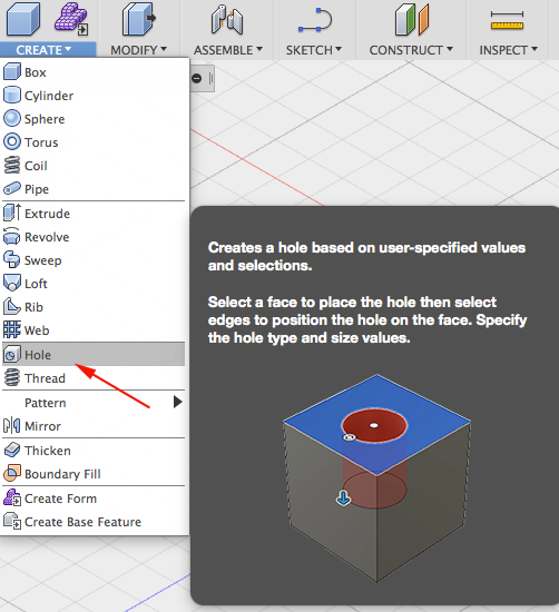
- Click Model → Create → Hole:
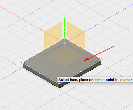
- Select the top face of the box:
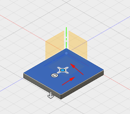
- Drag the center of the hole to the
center of the box:
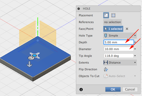
- Set Diameter and height:
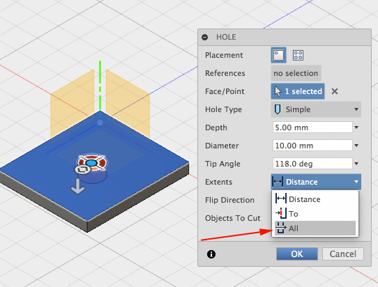
- Change Extents to All:
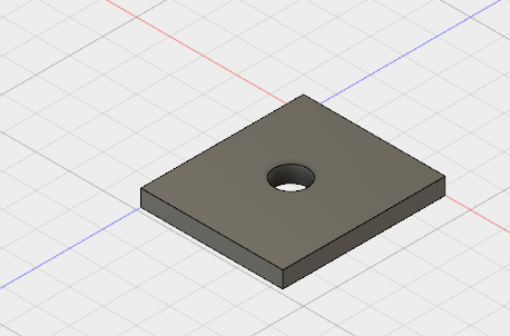
- Click OK:
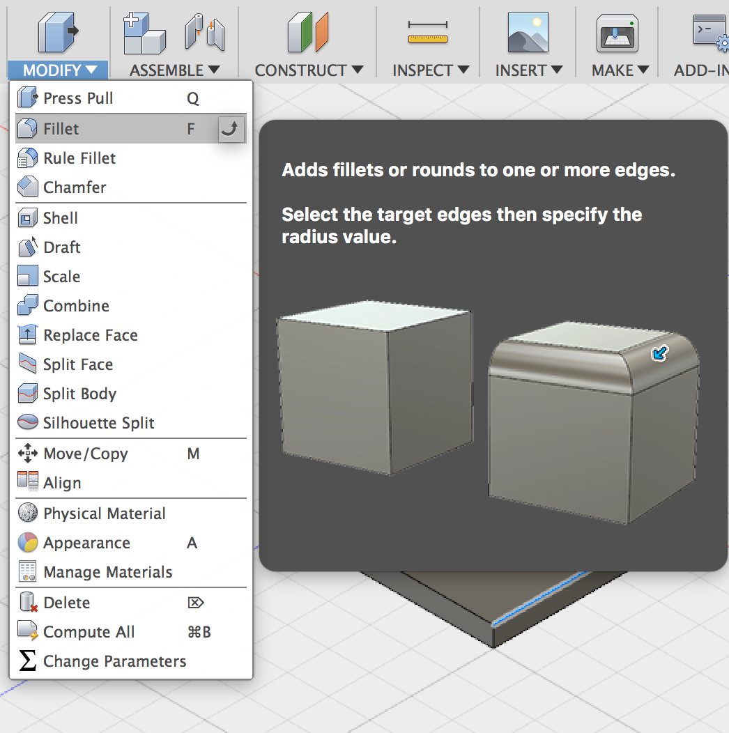
- Click on Fillet under Modify:
- Select all edges of the box
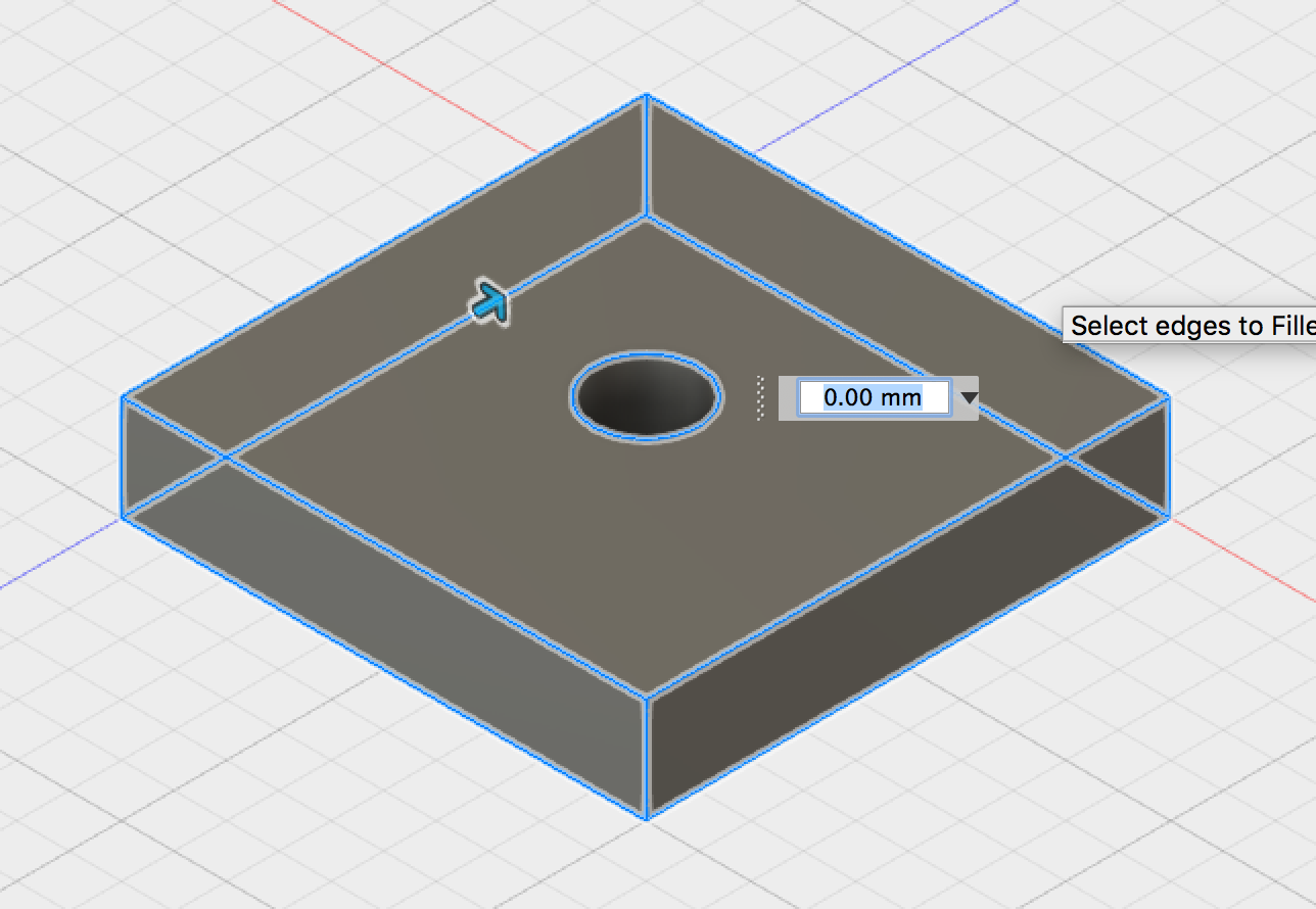
- Set the radius of the fillet:
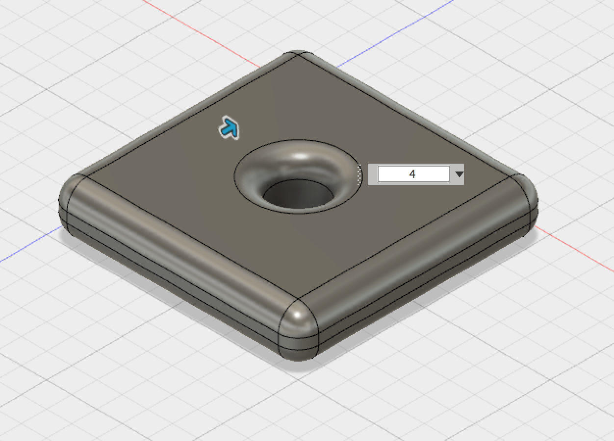
- Display the Data Panel.
Click in the upper left corner to display the Data Panel:
- The active project name is displayed at the top. Thumbnails of all the designs in the project are listed. All data is stored in A360 in the cloud.
- Click again to hide the Data Panel.
- Click next to Origin to display
the origin planes:

- Click the light bulb again to turn the origin planes off.
- Click the arrow next to Bodies in the browser to expand the folder. There is one body in this design.

- Find the timeline:

- CTRL+Click on the Fillet in the Timeline to bring up the menu. Select Edit Feature:
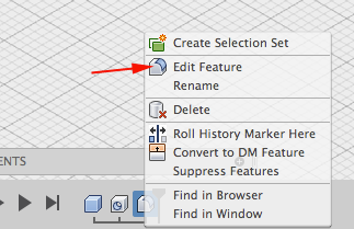
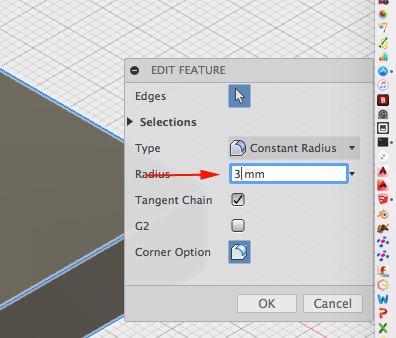
- Change the value of the radius:
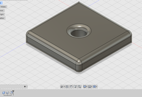
- Click OK:
- Select File→3D print or click on the Make Icon.
- Select and export the file.
Sculpting in Fusion 360: The Sculpt Workspace
Sculpting in Fusion 360 allows for the intuitive freeform creation of organic solid bodies and surfaces by leveraging the T-Splines technology. You can explore forms by pressing and pulling on subdivided surfaces. Sculpted forms are easily converted to solid bodies, and can be used in conjunction with Fusion 360's solid modeling commands.
One of the main advantages of T-Splines is the ability to add detail only where necessary - a single T-Spline surface can be smooth, while still having areas of high detail and remaining easy to manipulate.
T-Splines allows designers to:
- Add detail only where necessary.
- Create non-rectangular topology.
- Easily edit complex freeform models.
- Maintain NURBS compatibility
When in the Sculpt Workspace you have access to the Gizmo, which lets you manipulate vertices, edges and faces. The Gizmo has this name because twenty years ago 3D Studio Max called this tool the Gizmo.
The Gizmo allows you to translate a face, vertex, edge along an axis or a plane, and lets you scale and rotate your selection. If you double click on a single edge, Fusion will select the whole chain, or tangential lines.
When working in the Sculpt environment, the only option undo a step is to go back through through the last twenty or so steps. The number of undos is based on your RAM and how much cache space is left.
In addition to extruding and revolving, you can also generate a T-Spline body by sweeping a profile. Sweeping is commonly done with circles, however any closed shape can be used in conjunction with a line in a sweep to produce a solid.
This tutorial is based on "Overview of how to design your own headphones"
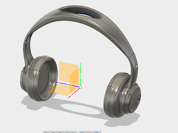
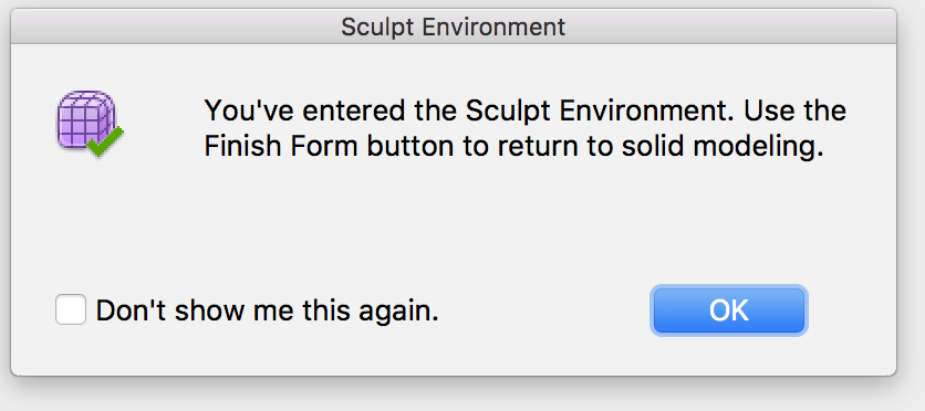
- Open the Sculpt Workspace. A dialog box will appear telling you to click Finish Form to return to the model workspace when you are finished sculpting. Select OK:
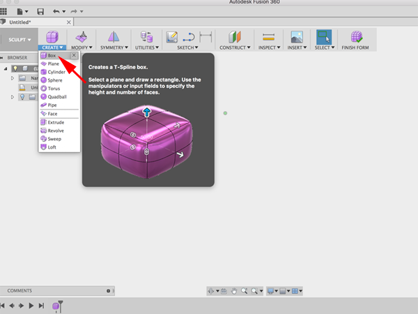
- Select the drop-down arrow under Create to expand the list of creation commands. Select Box under the Create menu to create a T-spline box:
- When you create a new primitive you first need to indicate which plane you want to build on and then enter the dimensions of the primitive. Select the YZ Plane :
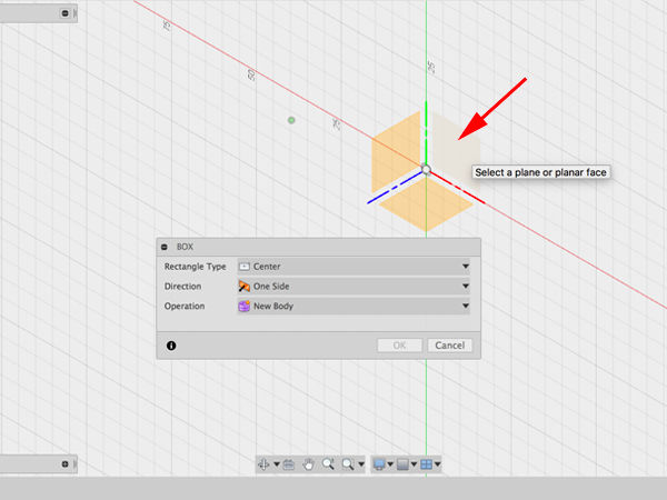
- Select the origin to specify the center point of the box 2D profile. Drag the mouse and click on the plane again to specify the initial size of the rectangle. Create a box with symmmetry across the length:
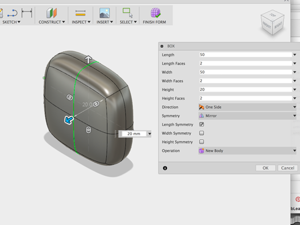
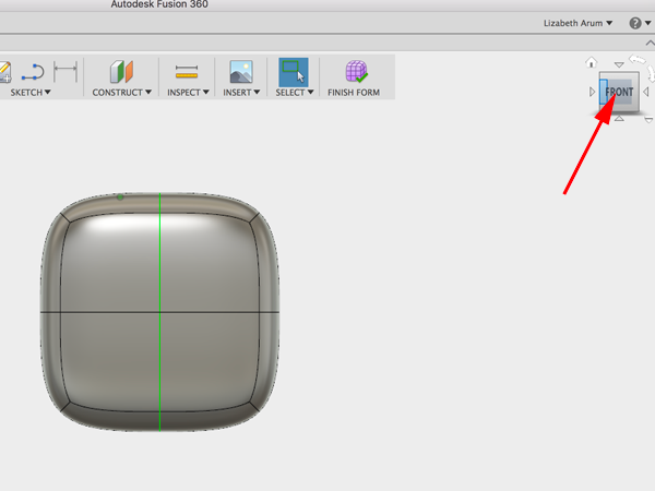
- Rotate the workspace to face the top of the box:
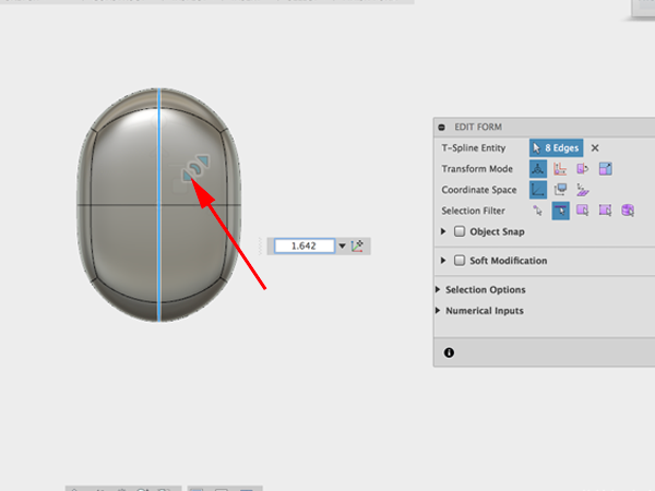
- Select edge and pull corner of gizmo to round box:
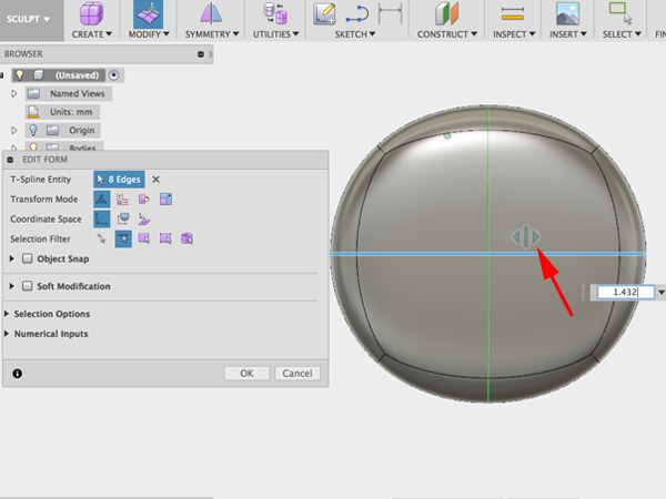
- Select other edge and drag gizmo to round:
- Select the four faces and while holding down on the alt key, drag to the left. You should create new faces:
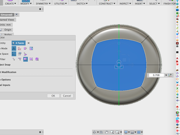
- Select the faces, hold alt while dragging to make smaller new faces and hold down alt while you extrude:
- Select the two bottom faces and hold alt while dragging to create new faces. Then hold alt while pushing in:
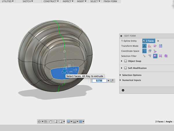
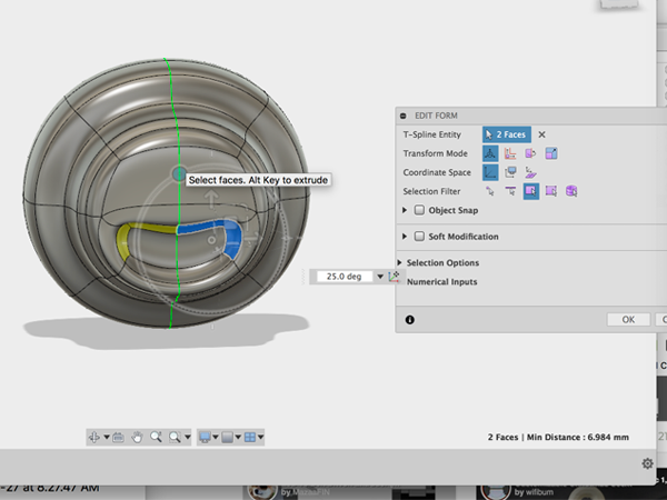
- Select the two faces and rotate:
- Rotate around to the other side of the model and select the four faces. Then hold alt and drag to the left:
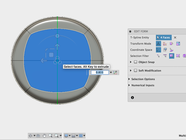
- Holding alt, move the new faces inward:
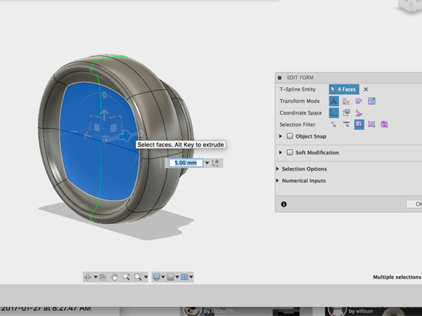
- Continue to edit until you get what you want:
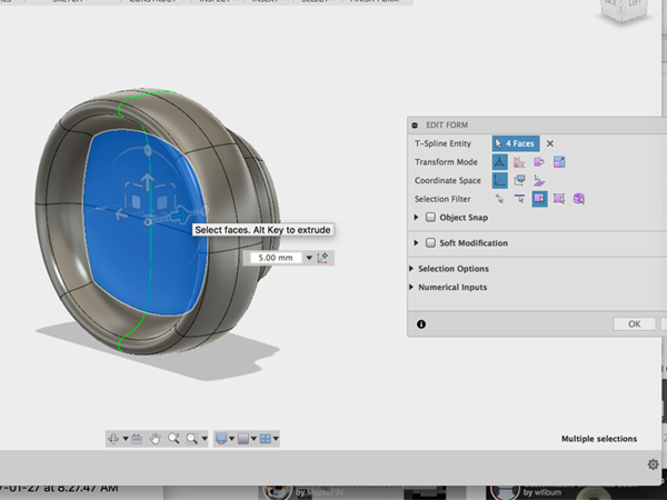
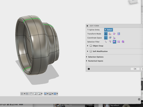
- Select Insert edgeClick on the center edge:
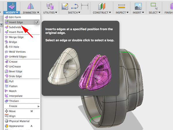
- Move the green edge forward:
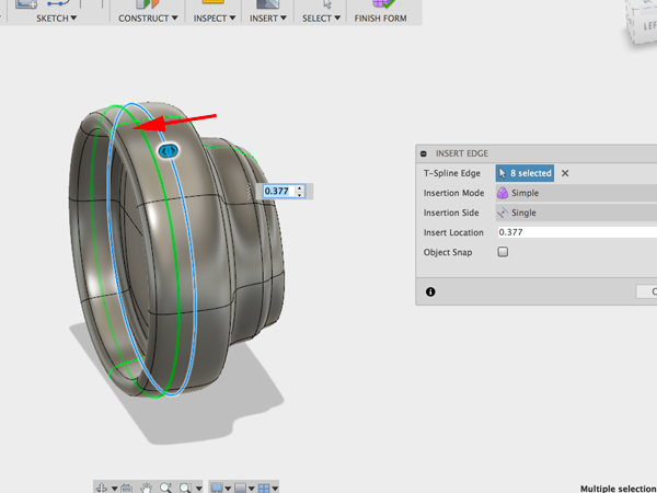
- Select the faces between the center edge and the new edge you made:
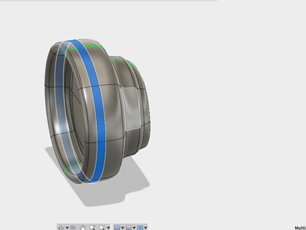
- Holding alt scale the faces up a little:
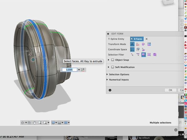
- Now using the gizmo, thicken the selection:
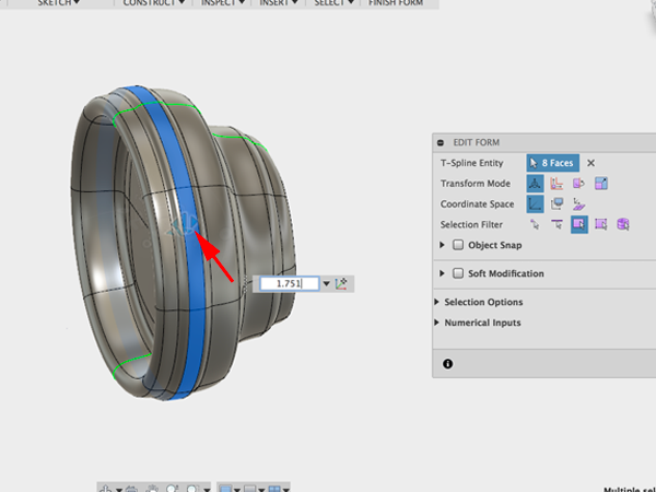
- Select the edge behind the center edge. You are going to make a hard edge:
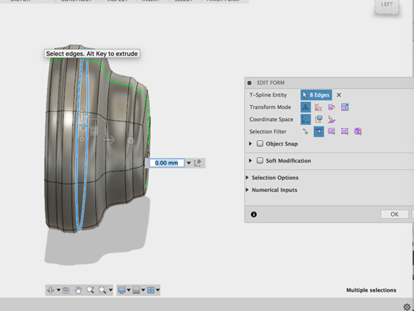
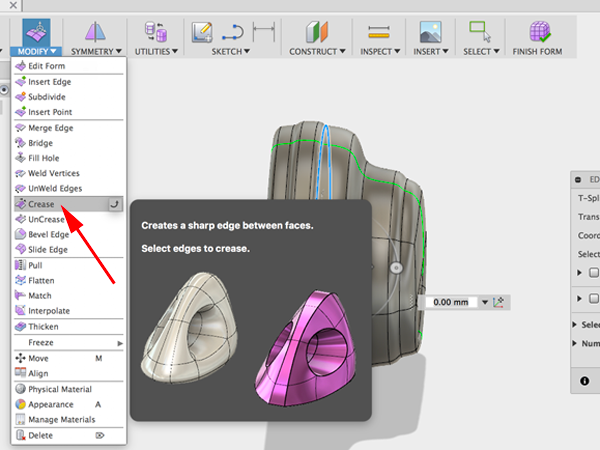
- To create a hard edge, Select Crease:
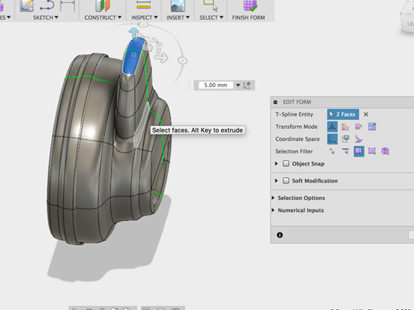
- Sculpt the back part until you get the shape you are after:
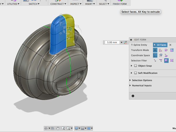
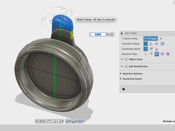
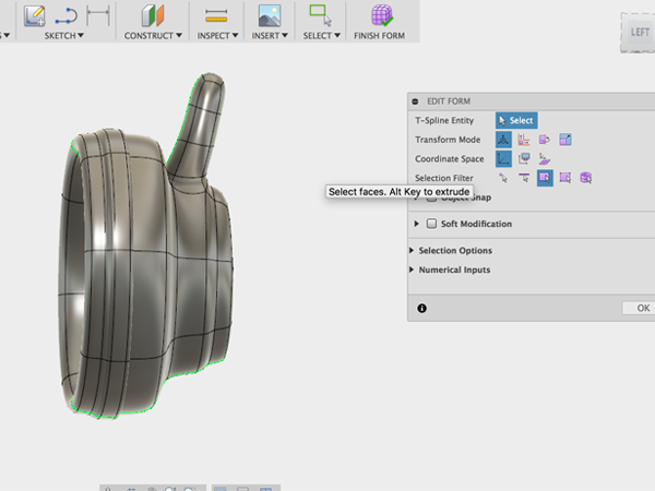
- Using the gizmo, move the entire form over and rotate slightly:
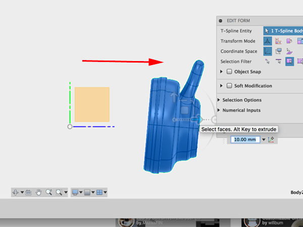
- To make the other side of the headphones, you can use Mirror - Duplicate:
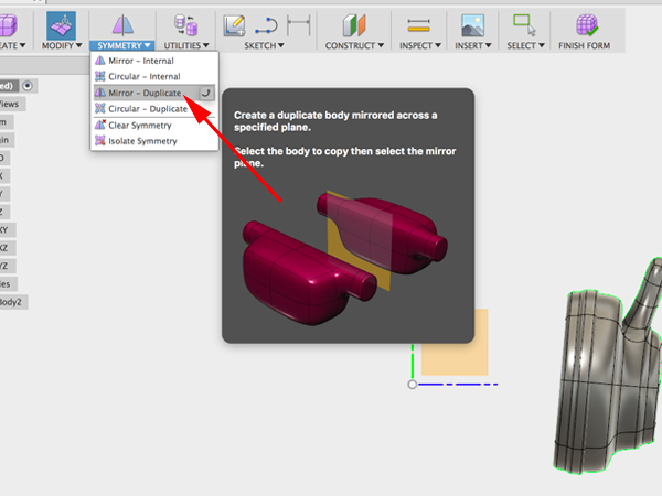
- For the Axis to mirror over, select the XY plane:
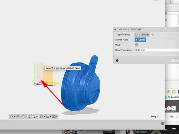
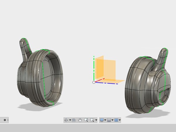
- Create a Sketch and select the YZ plane:
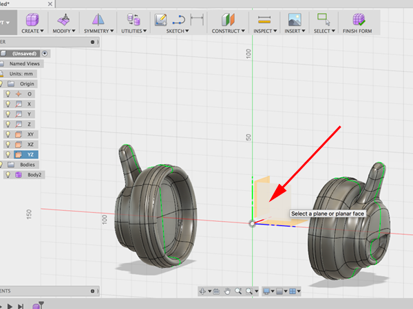
- Select 3-Point Arc:
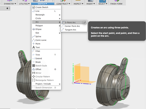
- Create the starting and ending points:
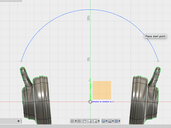
- Select Bridge:
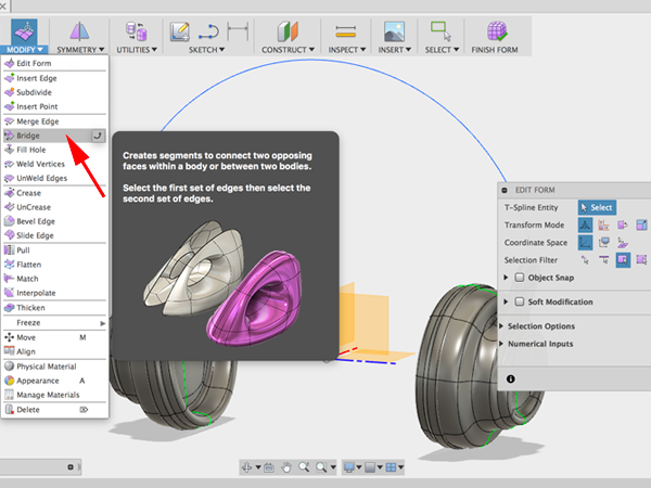
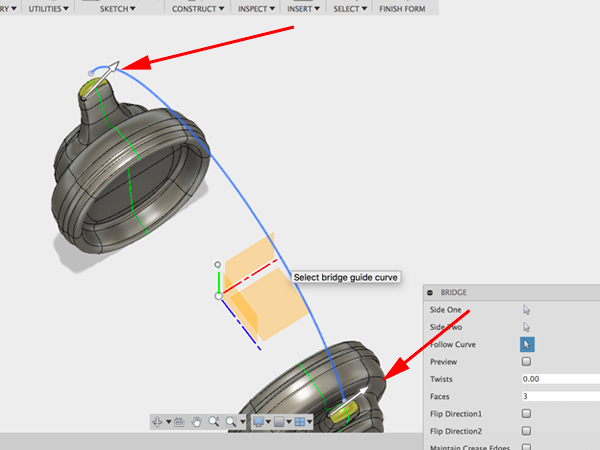
- First click on the top faces of one side, then select the top faces of the other side. Select the arc as the curve to follow:
- Adjust the properties so that the preview is positioned in the right direction:
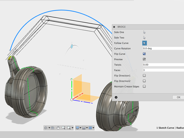
- Press OK:
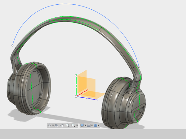
- Edit the top section using the gizmo. When you have the shape you want, CTRL+click on the surface in the browser and select Convert. This will convert your form from a surface to a solid body.
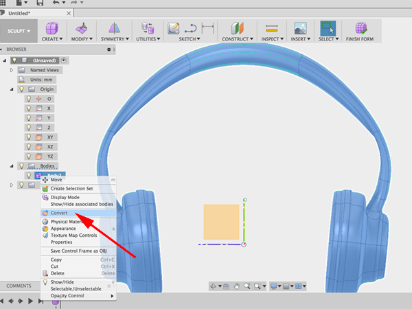
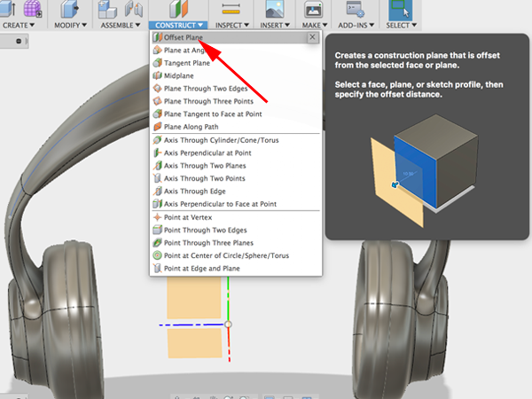
- Notice that you are now in Model mode. Seelct Offset plane:
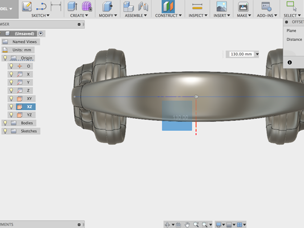
- Click on the XY plane and raise the offset plane above your form:
- Select Create sketch:
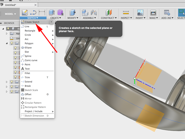
- Select the offset plane:
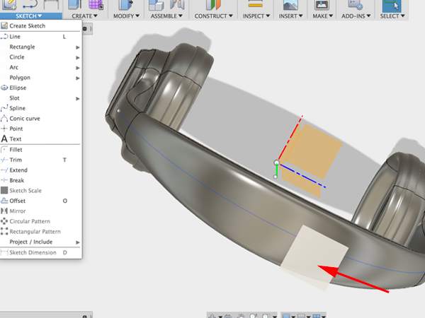
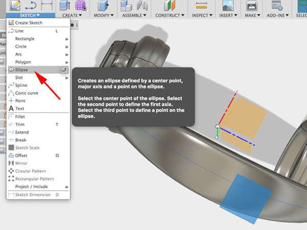
- Select Ellipse:
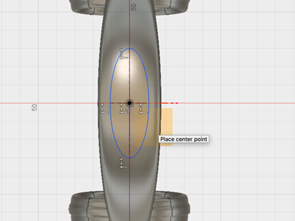
- Draw a centered ellipse:
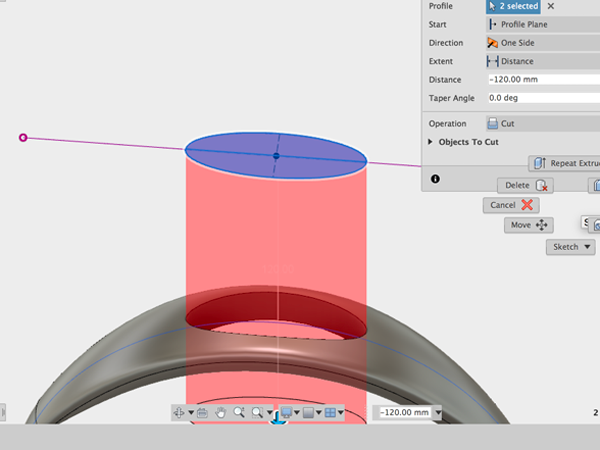
- Use Extrude to cut a hole:
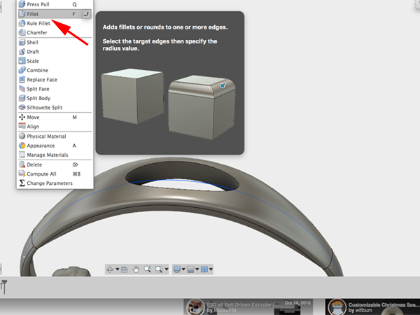
- Select Fillet and add fillets to the top and bottom of your hole:
- Save your work
Parametric Modeling and Sculpting: The Patch Environment
Creating a bend
The following information was derived from x's y tutorial.- Open Fusion 360:

- Open Patch mode:

- Create a spline:

- Select your plane:

- Draw your spline:

- Adjust your spline:

- Stop the sketch:

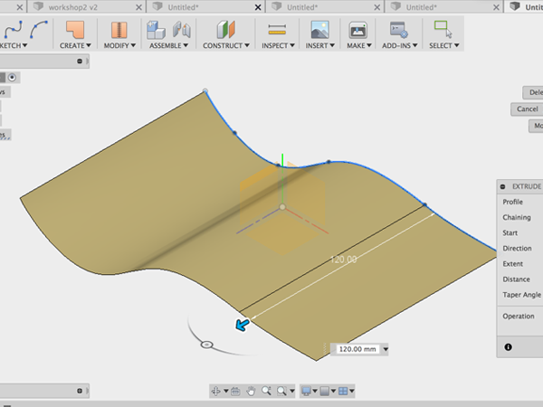
- Select Extrude:

- Extrude the spline:
- Create a new sketch and select the XY plane:

- Rotate to see that the bottom sketch is completely underneath the curved surface:

- Ctrl+click on the closed profile and select model extrude:

- Be sure to turn on intersect:


- In the Create menu, select Thicken and thicken the surface:

- In Model mode, select the top face:

- From Modify menu, select Fillet Rule:

- Add the fillet:

- Repeat for the bottom:

- Add the fillet:

- Return to Patch mode:

- Adjust the original spline and see how this affects your form:

- Adjust the other sketch:

- You can dimension your sketch:

- Then you can adjust the dimensions to affect the form:


Designing an Arduino Uno Enclosure
The following information was derived from x's Designing an Arduino Uno Enclosure tutorial.
- Create a New Project in Fusion 360.
- Download, open and save in your project:Kevin Schneider's Arduino
Here are dimensions for the Arduino:
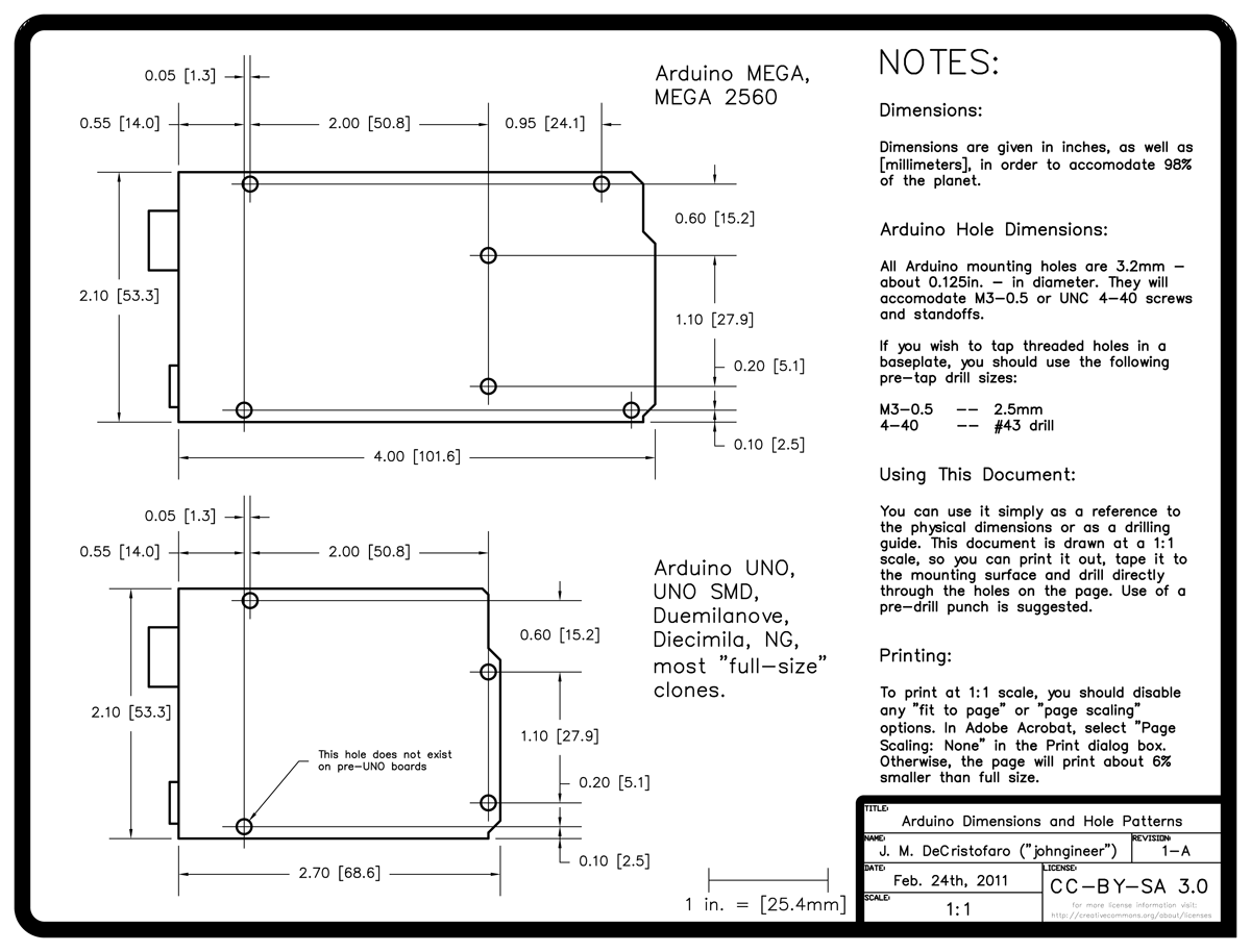
Here is an example of an Arduino enclosure:
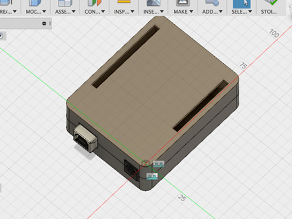
- Create a sketch and make a rectangle that is the dimension of an Arduino:

- Add an offset so that the Arduino can fit inside the enclosure:

- Offset by 1mm:

- Add circles with adiameter of 2.8mm. This is smaller than the Arduino holes, but this diameter will fit inside the 3.2 mm mounting holes:

- Add four circles

- Open up Sketch Dimension

- Use Dimensioning to arrange the mounting holse where they are supposed to be:

- Stop the Skectch:

- Select Extrude and extrude the base by 22mm:


- Select fillet:

- Apply a fillet of 3mm to the corners:

- Select Shell:

- Create a shell of 1.6mm. Make sure you select outside since you have created your shape that was offset by 1mm from the Arduino base dimensions:

- Create a Midplane construction plane:

- To find the midplane, click on the top face and then the bottom plane:


- You are going to use the midplane construction as a splitting tool. Select Modify:Split Body:

- Select the box as the body to be split and the plane as the tool:

- In the browser, hide the top of the box:

- Select extrude and extrude the circles by 15mm (11mm to reach the top and 4mm to extend to the other side):

- Select Create Sketch:

- Create a new sketch on the face of the bottom of the box:

- Make four circles with the same center point as the pins. Make the diameter 4mm:

- Select Extrude:

- extrude by 4mm and make sure New Body is selected:


- Hide the bottom. Show the top:

- Create a sketch on the interior face of the top part of the box:

- From the Sketch menu, select Project:

- Turn off the top body, turn on the bottom body and select the top faces of the pins to project:

- Turn off the bottom:

- Use the projected circles as your guide to make new circles with a diameter of 3.2mm:

- Create another set of circles with a diameter of 5.2mm:

- Turn on the top body:

- Select Extrude and extrude the cylinders by 10mm:

- Tuurn off the top and turn on the bottom. Select Chamfer:

- Select the tops of the pins and chamfer by .4mm:

- Select Combine:

- Select all the elements you want to comprise the bottom of the box:

- Select Combine again. Select all the elements you want to comprise the top of the box:

- CTRL+click on the bottom body in the browser and select Make Component. Name the component bottom:

- CTRL+click on the top body in the browser and select Make Component. Name the component top:

- Navigate to the data panel. CTRL+click on the Arduino and bring it into the current project. You can also rotate it by -90:

- In the Browser, CTRL+click on the bottom and select Ground. This will pin the component in place:

- Select Assembly:Joint:

- Select the bottom of the mounting hole on the Arduino:

- Select the top of the corresponding 4mm cylinder on the bottom. Make the connection Rigid.The Arduino should move into place:

- Select Assembly:Joint:

- Select these two points on the top and bottom to align them. Make the connection Rigid:

- Create an offset plane:

- Select the side face:

- Create a sketch and select the offset plane

- Select Project

- Carefully select the edges of the power and USB jack:

- Turn off the Arduino. Offset the edges by .5mm:

- Select Extrude:

- Extrude the offset and the original edges just to the other side of the bottom wall:


- Create a sketch on the top of top. Select Project. Hide top and click on the diagonal corners of the Arduino pins:

- Turn the top back on:

- Use the Rectangle to create rectangles based on your projected pins:

- Select Offset:

- Offset the rectangle by .5mm:

- Save.
Collaboration
On left side, open the Data Panel. Collaboration starts with fact that it is cloud based software. You don't store your files locally. Files are saved on Autodesk servers at Amazon Web Services, so you'll always be able to see your files.
Fusion allows you to add people to a project. Once invited, your invitee will get an email. They can then see your project in their data panel. You might be asking: Does that mean anyone can edit, download and delete your files? The answer would be yes.
Fusion is working on preventing that, but at the moment you either have full access to a project or you don't have access, so be careful.
Two people can open the same file at the same time, but they will be working on different instances of the file. Once on person saves the file, the other person will see that they are not working on the most recent version. If they update the file, they will lose everything they have just done and see what their collaborator has done. If you save first, then your version becomes the most recent.
A new version is created on the server in Seattle Washington. The collaborator will get a notification that they are not working on the most recent version, that it is out of date. If you update you will create a new version with all the changes made in the last version, but you will lose what you were working on.
Companies pay PDM systems, basically a Data management systems 10-15K per person a month. Fusion offers this functionality for free. The data will always exist on the server—this is beneficaial. Large companies might pay millions for this functionality. All this functionality is taken care of from the cloud.
Ability to add comments. Click on an aspect of the model, take a photo, write a comment.
Information: who is using the file, who is doing what, versions A lot of viewing and collaboration capabilities that are not in Fusion 360. In the data panel, click on the name of the project ( use firefox or chrome) and you will be taken to myhub.autodesk360.com All the projects are now viewable in a browser.
- All the files
- Activity-whats going on
- overview-information, thumbnail. the thumbnail allows you to share what your project looks like with someone who does not have the same modeling application as you. So if someone does not have fusion, they can still access the file as long as they have been invited
You are able to view versions and notes. At any point you can select one of the previous versions and promote it to the most recent version. Handy if new changes are rejected
Viewer
Viewer is a powerful option. Works with any browser. works with almost almost all Autodesk CAD formats and all standard formats, SolidEdge, ProE and some Solidworks files.- Explode
- Mark up
- Notes, add comments
Properties
Share your files Calendars—set up due dates You can put any files in the project and they will be usable in the viewer. So if you upload a word doc and your collaborator does not have Word, they will still be able to read it in the viewer.Collaboration in Fusion 360
Troubleshooting
Troubleshooting Slideshow
- Create a new Design.
- Open Preferences by clicking on your name in the upper right corner. Select Preferences.
Select Preview. Enable the top four options: Apply:

- Click on Create Form to go in the Sculpt Environment.
- Select Create →Cylinder:

- Click on Home button then choose the plane to start the cylinder:

- Click on origin to set center point. Then click at a distance:

- In the Dialog window, set the Diameter to 4in:

- Set the Diameter Faces to 24:

- Set the Height Faces to 2:

- Set the Height to 11in:

- Click on the magnifying glass to zoom of fit:


- Select Modify→Edit Form:

- Double click on one of the segments in the middle to select the entire loop. Then scale. Enter .4 in the dialog box:

- Change the view to Top. Double click on the top edge, then Shift double click on the right edge, then Shift double click on the bottom edge and then Shift double click on the left edge:

- Rotate to confirm you have selected all the edges:

- Select Modify→Crease:

- Click on OK:

- Turn off Shaded with Visual Edges by selecting Shaded. This will let you see the crease:

- Re-enable Shaded with Visual Edges. Set the view to Top:

- Double click on the five segments between the top and right edge:

- Rotate to confirm you selected all of them:

- Press Delete:

- Return to a top view. Double click on the five segments in the top left quadrant:

- Delete:

- Select Symmetry:

- Select Mirror-Internal:

- Click on the flat faces on the right:

- Press OK. Change to Top view:

- Select Edit Form. Click on the top right vertex and shift click the bottom left vertex. Then drag the inner corner of the widget out:

- You should have a shape similar to this:

- Click OK:

- Select Modify→Crease:

- Double click on the segments to the right and left of the vertices pulled:

- Click on Finish Form:

- You need to make this solid:

- Turn on the Origin:

- Select Construct→Plane Through Three Points:

- Click on three different vertex points at the top of the form:

- Select Create→Boundary Fill:

- Click on the top plane , the form and the bottom Plane for Select Tools (hold the mouse down to select obscurred objects):

- Click on the checkbox in the middle for Select Cells:

- Make sure Operation is set to New Body. Press OK:

- Turn off Construction plane:

- Set the view to Bottom. Create a New Sketch:

- Click on the Bottom face:

- Select Circle. Click on origin and make a half inch circle::

- Select Offset or type o:

- Click on the circle and set the offset to 2mm:

- Click OK:

- Drag your dimension out so you can see it:

- Turn off Bodies:

- Click on Home icon to change view.Stop Sketch:

- Select Create→Extrude or type e:

- Select outside circle and outside profile and extrude down:

- Set the extrusion to 10mm:

- Click OK:

- Show sketch and select Create→Extrude or type e:

- Select the outer ring again:

- Pull it down 5mm (you want subtract):

- Click OK:

- Hide Sketch, select extrude, click on the face of the outer ring:

- Extrude it 12 in and change the Operation to New Body:

- Hide the the body you just created and turn on sketch:

- Extrude the inner and outer circles. Turn on the first body, set Extent to Object::

- Click on top face:

- Click OK:

Reference Images
When sculpting a shape with T-Splines it is helpful to have a reference image to guide you. Reference images can be sketches or photographs that are set in the background of the workspace to model from. In Fusion 360 you can attach an image to a work plane and then calibrate the image so that you are modeling in the correct scale.- Select Insert:Attached Canvas
- Select a plane to indicate which plane the image should be attached to.
- In the dialog window, click the Select Image button and navigate to your image
- Lower the opacity to around 85. Check the box for Display Through to ensure that the canvas can be seen through your T-Spline form. Click OK: Note: You don't need to be concerned about the size and scale of the image at this point. You will adjust the scale using the Calibrate tool. Calibrating the image ensures that you are modeling in the correct scale in the workspace
- In the Browser, click the drop-down arrow next to the Canvases folder
- CTRL-click on the image and select Calibrate.
- Click on the ViewCube to change the view.
- Click a point on one side of what you know the dimension of. Then click on the other side. Enter the measurement. The attached referenmce image will scale up accordingly
This tutorial is based on Surface Modeling with Fusion 360
- Download this image:

- Select Insert:Attached Canvas and navigate to the image you downloaded:
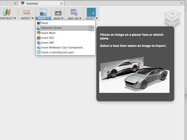
- Select the XY plane to attach the image to.
- Lower the opacity to around 85. Check the box for Display Through to ensure that the canvas can be seen through your T-Spline form.
- Click OK.
- In the Browser, click the drop-down arrow next to the Canvases folder
- CTRL-click on the image and select Calibrate.
- Click on the ViewCube to change the view.
- Click a point on the top. Then click a point on the bottom. Enter the measurement of 100. The attached referenmce image will scale up accordingly
- CTRL-click on the image in the Canvases menu and select Edit Canvas.
- Move the canvas to align with the axis:

- Open the Sculpt environment:
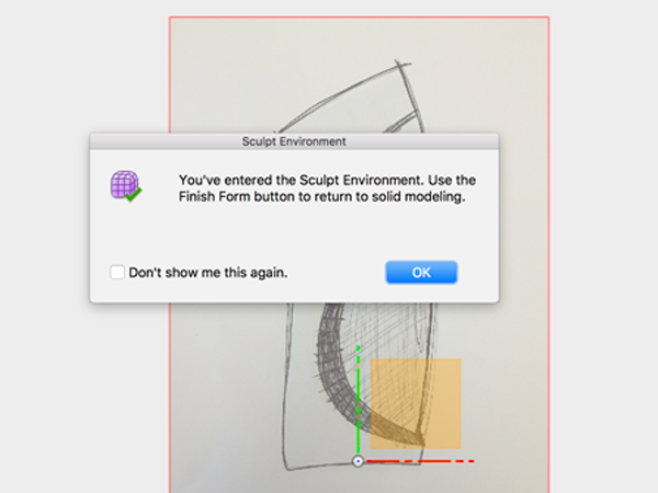
- In the Sculpt Environment add a cylinder to the XZ plane:
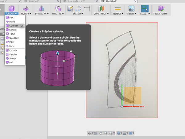
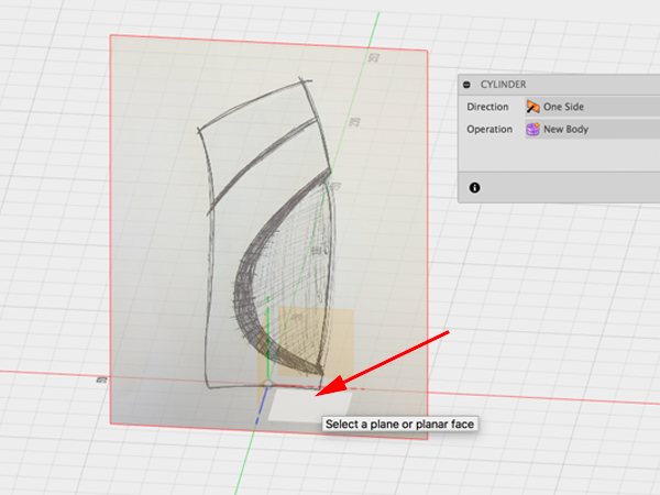
- Adjust properties of cylinder:
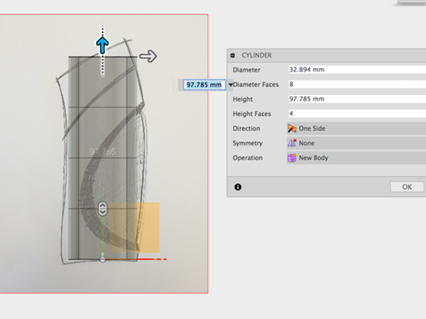
- Edit the form to match the sketch:
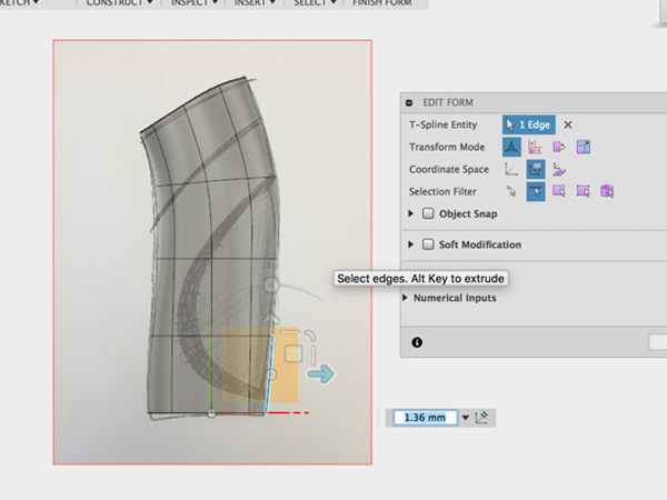
- Finish the form and enter the Patch environment:
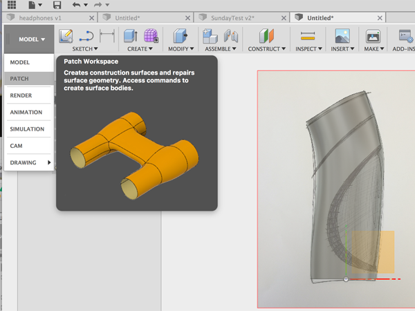
- Select Create Sketch:
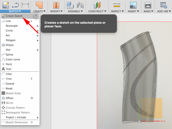
- Select the canvas to sketch on:
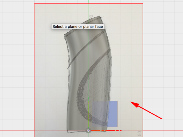
- Select spline:
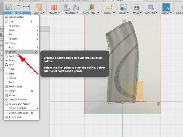
- Draw splines to matc the sketch:
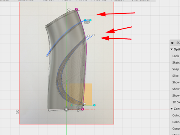
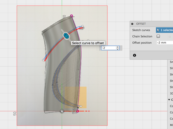
- Select offset to the top spline:
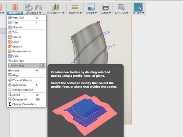
- Select Split Body:
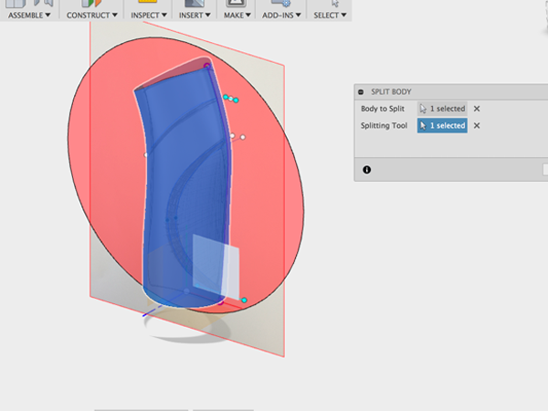
- Click on body to split and plane to cut with:
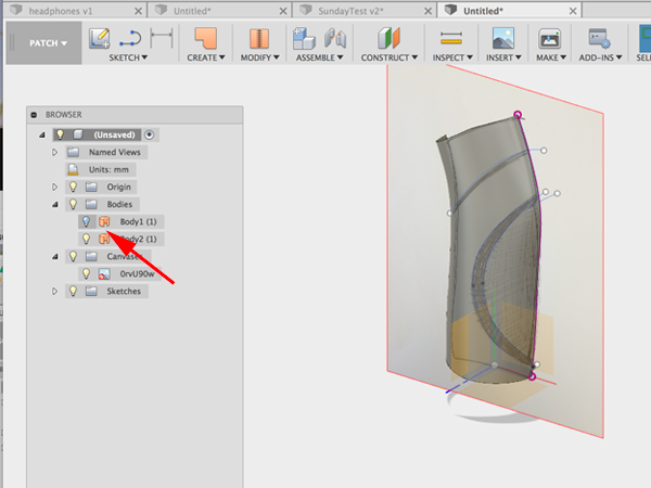
- Turn off the back:
- Select Split Body again:
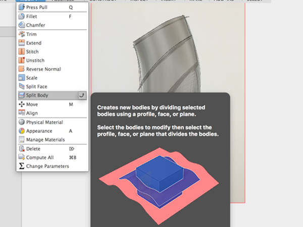
- Click on the body to split and the top spline to cut with:
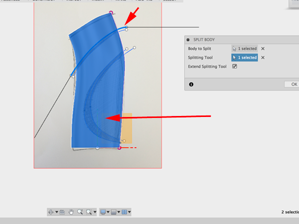
- Make another split of the body and the top spline of the second group to cut with:
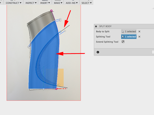
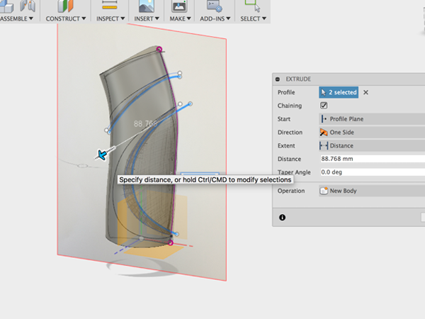
- Extrude the offset line and the second spline:
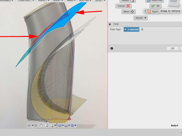
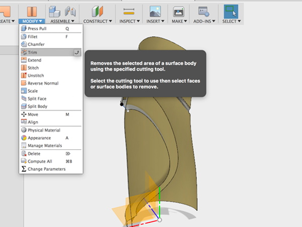
- Select Trim:
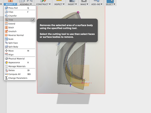
- Select the extruded surface and the small piece below the first split:
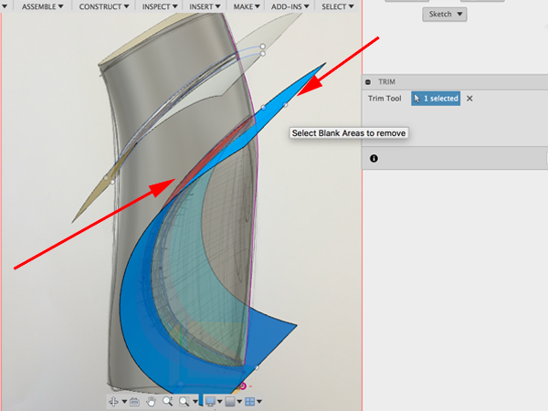
- Select Trim again:
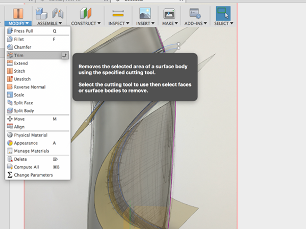
- Select the surface and the small piece above it:
- Turn off the canvas:
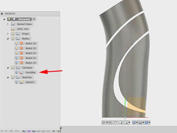
- Select Offset from the Create menu and select third piece:
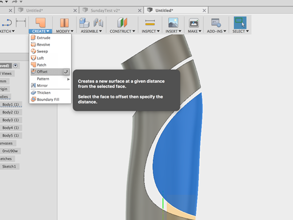
- Move the piece:
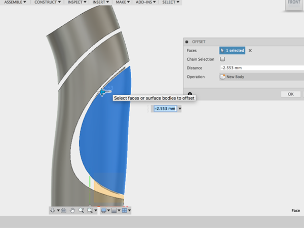
- Turn off the original piece:
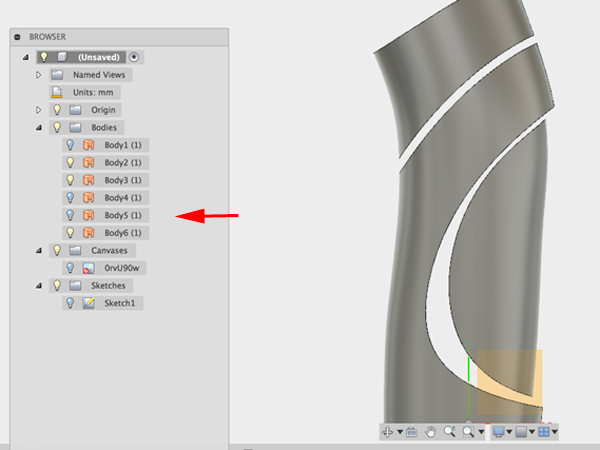
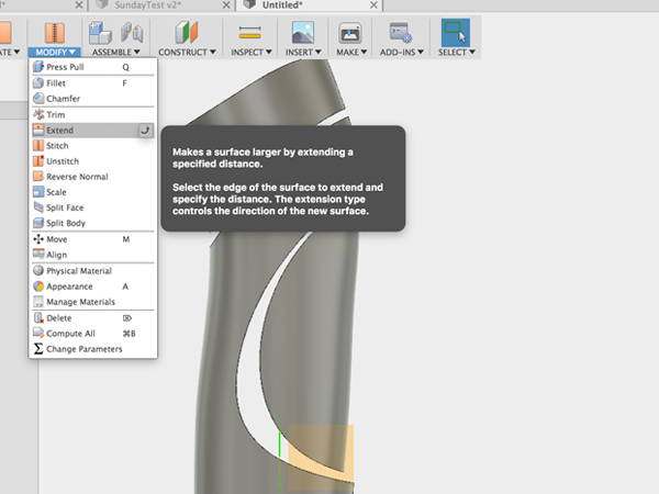
- Select Extend and select the edge of the offset piece:
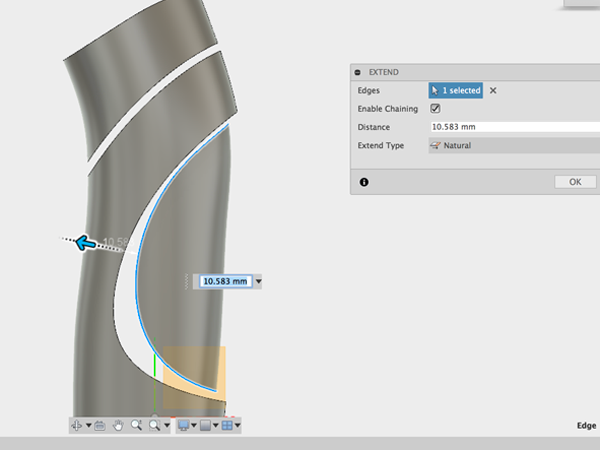
- Move the edge so that it completely extends through the body:
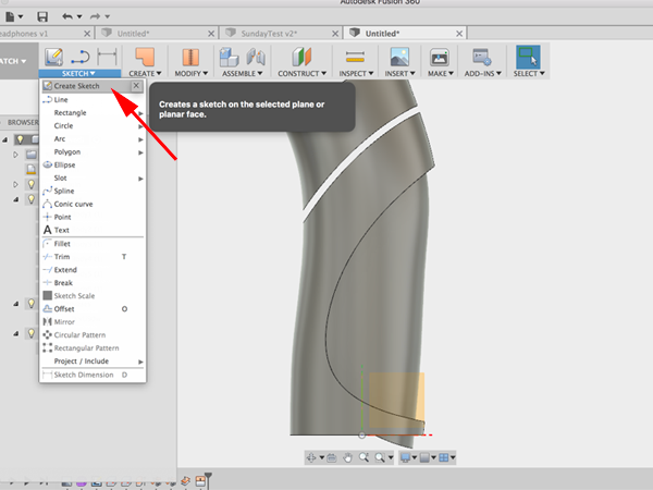
- Create a sketch:
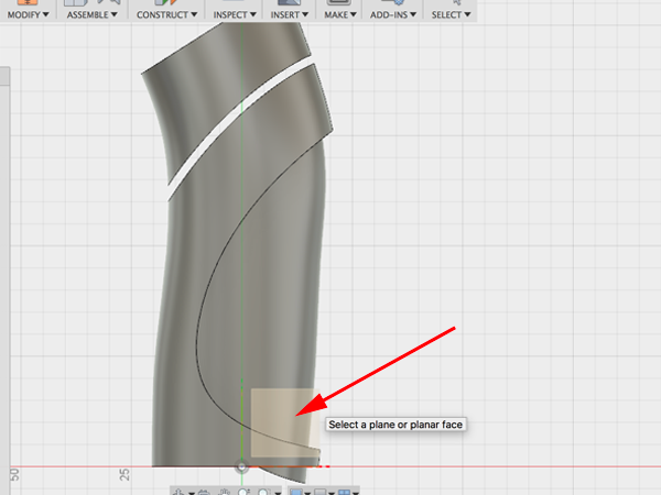
- Select the plane:
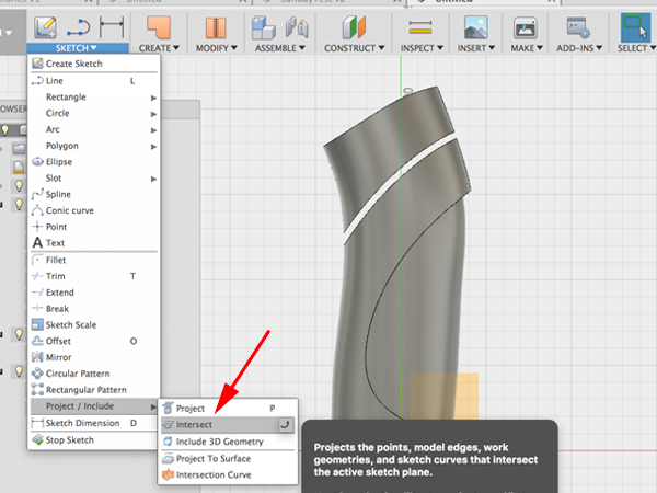
- Select Project:Intersect:
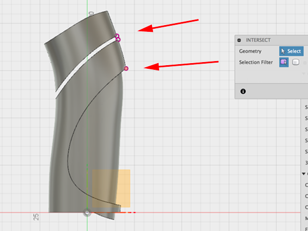
- Select the three points:
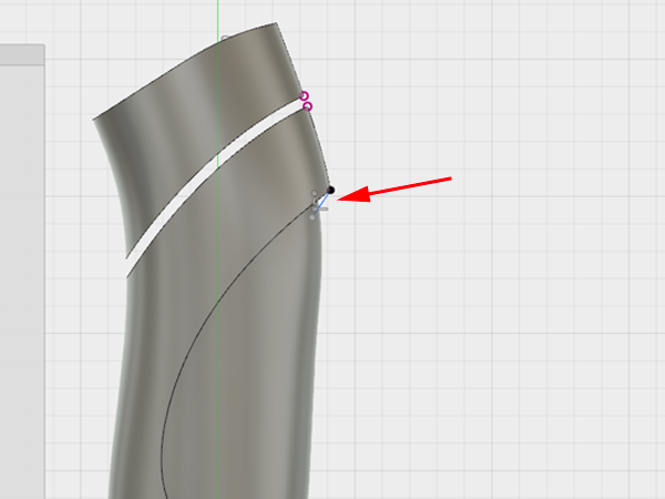
- Make a small line:
- Select 3-Point Arc:
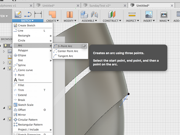
- Create the arc between the 2 points:
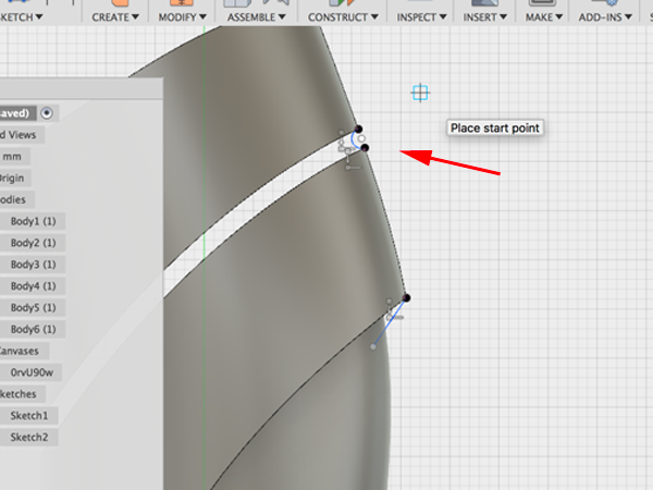
- Click Sweep and select the arc as the profile:
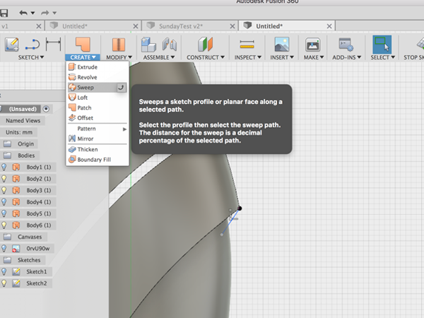
- Click on the top line for the path:
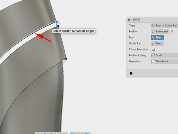
- Click on the bottom line for the rail:
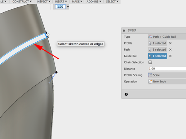
- Select Sweep:
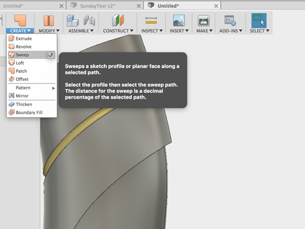
- Click on the small line for the profile:
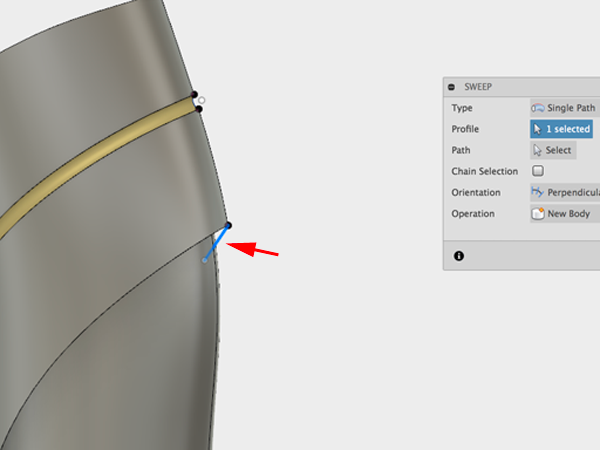
- Click on the line for the guide:
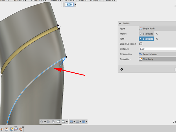
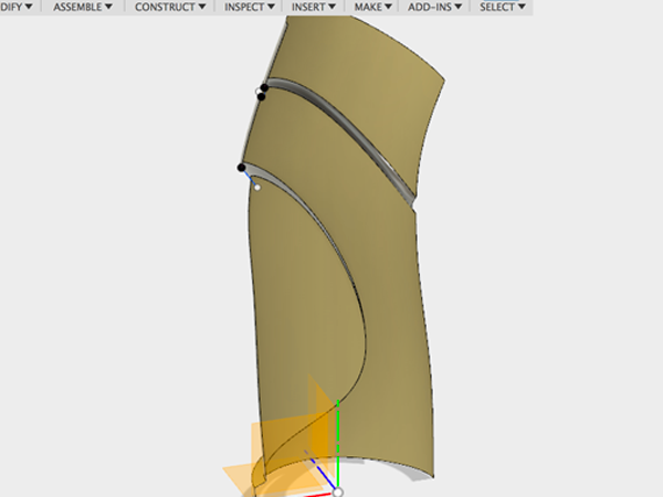
- Turn and trim:
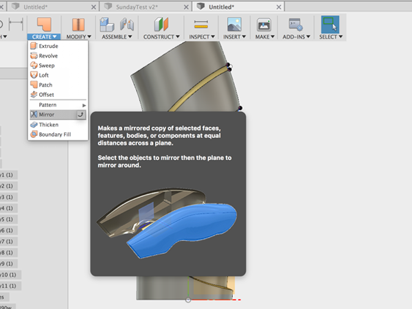
- Select Mirror:
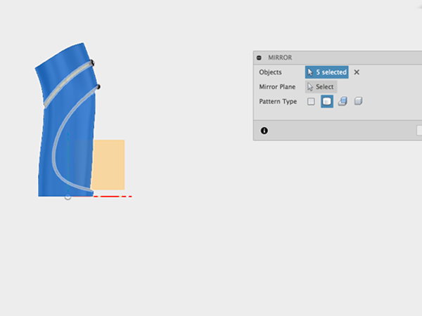
- Select all the parts:
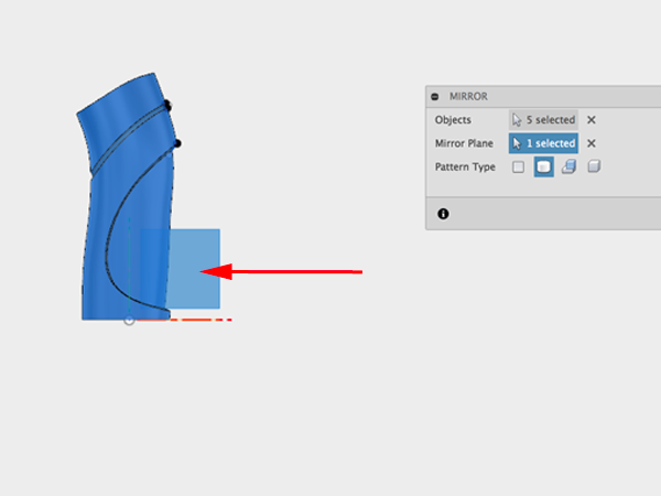
- Select the plane to mirror over:
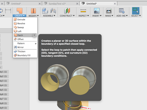
- Select Patch:
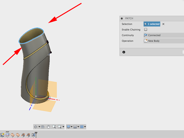
- Select the top edges:
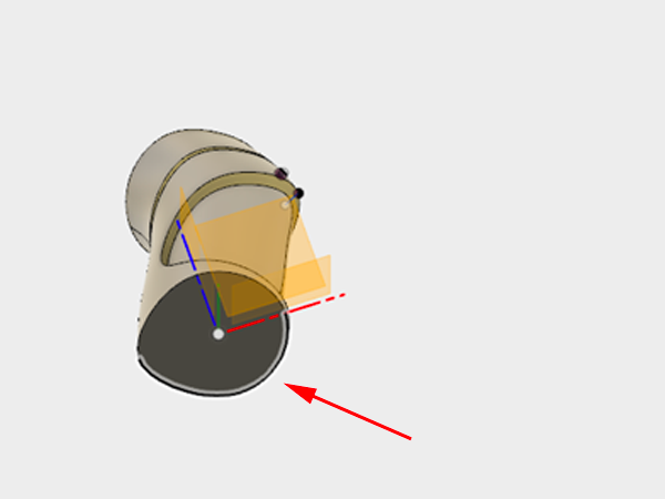
- Patch the bottom:
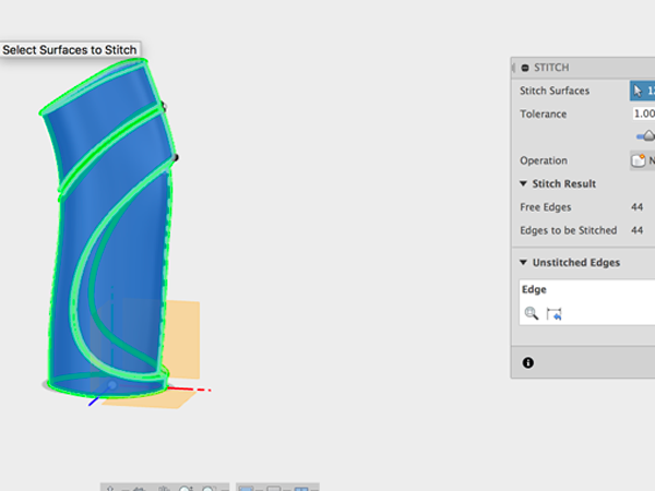
- Select Stitch:
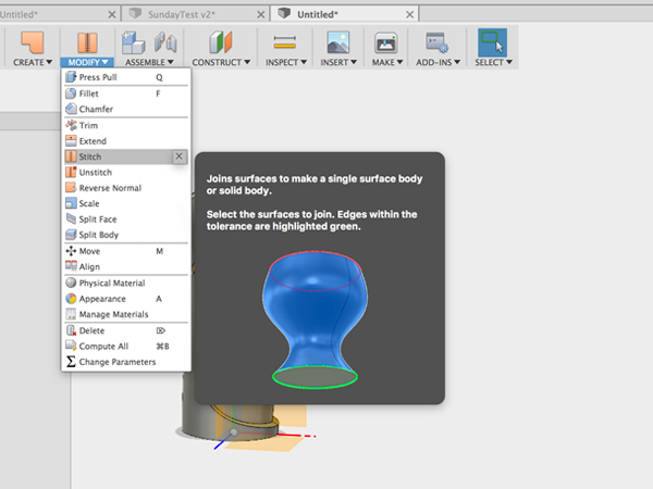
- Select all to stitch:
Additional Resources
Modeling Basics
List basic modeling techniques:
- Constructing primitives
- Drawing profiles
- Revolve
- Sweep
- Extrude
- Loft
- Shell
- Slice
- Union
- Intersect
- Subtract/Difference
- Fillet
- Chamfer
Constructing with primitives
The term geometric primitive means the simplest (i.e. 'atomic' or irreducible) geometric object that a system can handle (draw, store). In other words primitives are forms, including cubes (or boxes), spheres, and cylinders. In Fusion 360 you also have Torus, Coil and Pipe. These last three forms are considered to be primitives because they are the building blocks for many other shapes and forms.
When you start modeling, you need to create objects, and the easiest way to start modeling is by creating geometric primitives, such as spheres, cubes, and cylinders. All modeling programs will allow you to translate your objects so that you can move and rotate them. You can also combine your primitives to create more complex objects.
Look around you. Much of what you see can be deconstructed into more simpler primitive shapes. For instance, a lamp can deconstructed into a handful of simple shapes:
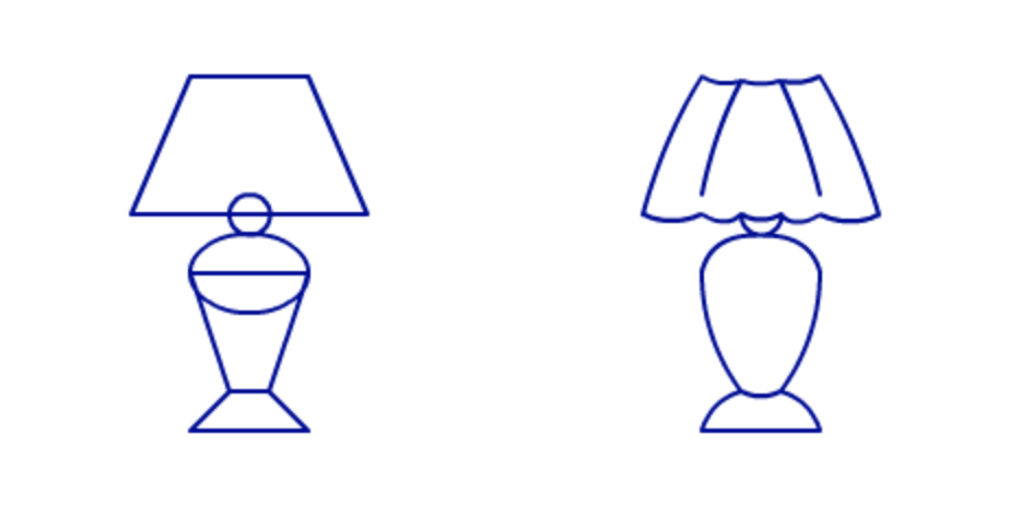
Image from drawnbyhislight

Or break down a mallet:
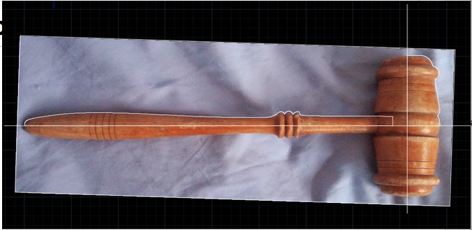
Image from Todd Blatt
Or a fire hydrant:
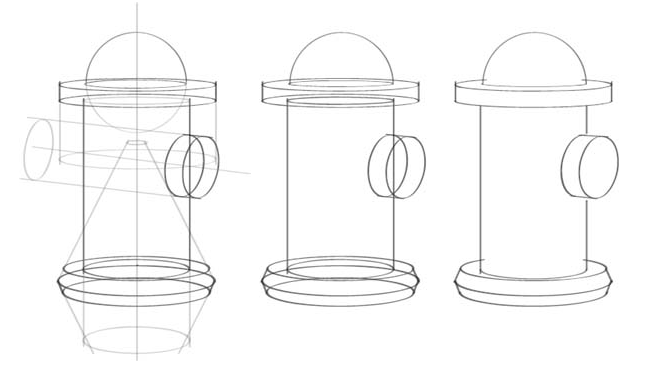
Image from Henry, Kevin (2012-08-27). Drawing for Product Designers (Portfolio Skills) (Kindle Locations 109-115). Laurence King. Kindle Edition.
Exercises
- Create a robot, a snowman, a or set of barbells using the primitive shapes.
- Deconstruct an object you see around you into a series of primitive shapes. Do it on paper first, then model it.
Source: Primitives
Drawing Profiles
Sketches are the foundations for creating features, as once sketches are created they can be used as profiles for creating 3D features. You can draw your sketches on a plane or on an existing face of a part. You can either draw your profiles or you can use projections of existing geometry.
Keep in mind
- You can start sketching on any plane.
- You should center your sketches on the origin.
- You can use constraints and dimensions to your sketches.
- Open Fusion and Select Create Sketch:

- Select the plane you want to sketch on:

- Select Polygon→Circumscribed Polygon:

- Start drawing your polydon from the center and start to pull from center:

- Press TAB and enter the number of sides you want. In this case, we want 8:

- Click on the Horizontal Constraint and then on one of the segments:

- Select Sketch Dimension or just type D:

- Click on one of the segments:

- Pull the bar away from the polygon

- Double click on the number and change it to 20:

- Select the Line tool or type L. Draw a vertical line some distance away from your polygon:

- Select the Circle tool or type C. Create a circle of any size where each of the line segments of the polygon meet:

- Keep adding circles:

- Add enough circles so that each corner is covered:

- Select the equal constraint and click on the first circle then on the next one:

- Keep clicking on circles. The next pair should be second and third, then third and fourth:

- Keep going:

- Select Sketch Dimension of type D and measure the diameter of your first circle. Remember to pull out the measurement so that you can read the value:

- Double click on the value and change it to 4:

- Click on Stop Sketch:

- Select Revolve under Create:

- Click on the polygon and all the circles and set the radius to 70°:

- In the Browser, turn off the new body and turn on the sketch:

- Select Extrude or type E:

- Select the polygon and all the circles and extrude in the negative direction:

- Back in the Browser, turn on the Body and make sure the Operation is set to Join:

- Select Shell from under Modify:

- Select both top and bottom faces:

- Set the width of the wall you would like:

- Et Voilà:

Exercises
- Recreate one of the following:


- Create a Knot Burr Puzzle
Revolve
REVOLVE spins a profile around an axis. The profile can be revolved at any angle up to 360°. You can also get some interesting shapes by starting with complex profiles.
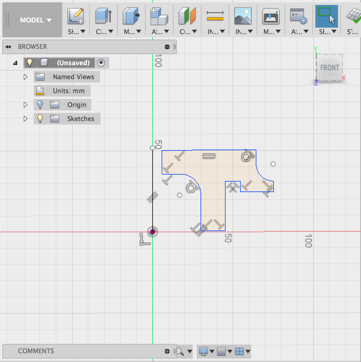
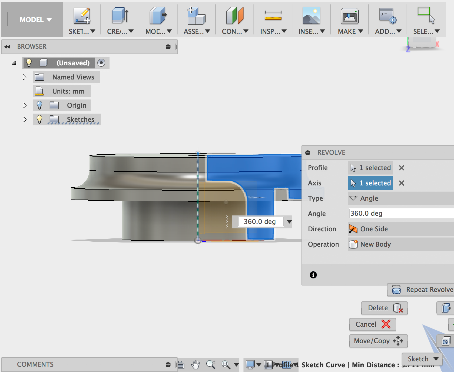
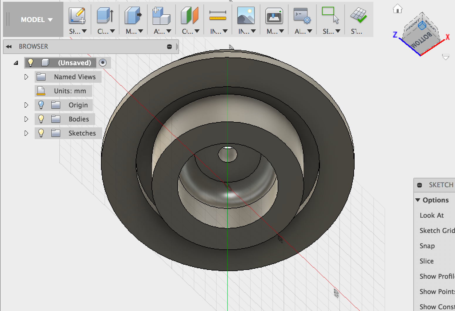

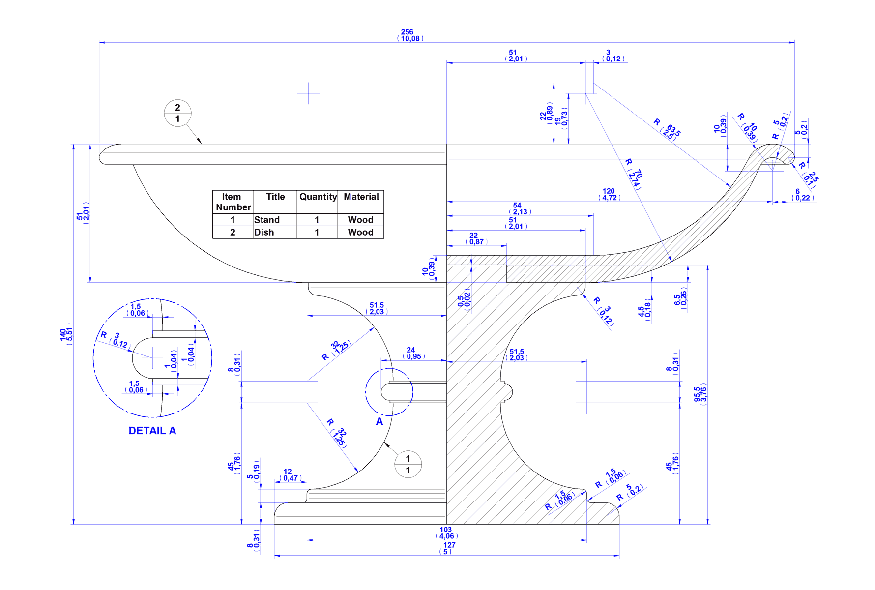
Images from www.craftsmanspace.com
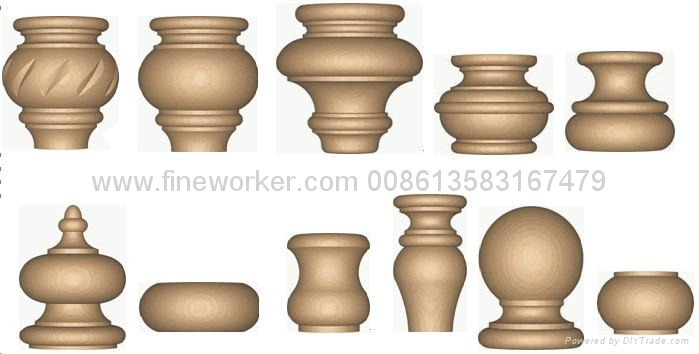
Image from www.diytrade.com

Image from Wikimedia
Exercises
- In most CAD programs a Cone is a primitive shape that comes with the basic set. Fusion 360 does not include a Cone. but you can create your own cones using revolve.
- Bring in a SVG to be your profile, then revolve it to create a customized bead.
- Sphericons
Sweep
- Create a new Design. Then select Create Sketch and choose the bottom plane. Then select Polygon:

- Set your size and click on TAB to set the number of sides (8):

- Click on the horizontal constraint and then click on a segment of the polygon to straighten it out:

- Click on Stop Sketch:

- Create another sketch:

- Select the vertical plane:

- Select the Line tool or type L and create a vertical line:

- Click on Stop Sketch:

- Create a coil by selecting Coil. Click on the bottom plane. Start at origin and pull out to one of your polygon's vetices:

- Set the type to Revolution to Height. Set revolutions to .5. Set height to your vertical line. You can play around with section size:

- Select Sweep:

- Select Path and Guide Rail. Click on your polygon to select the profile:

- Click on the line of the Coil to select the path:

- Click on the vertical line to select the Rail:

- Make sure the Operation is set to New Body:

- You now have your outer box:

- Turn off your bodies and turn on Sketch 1:

- CTRL click to edit Sketch 1:

- Select Offset in the Sketch menu or type O:

- Set the offset to -1mm:

- Click on Stop Sketch:

- Make sure both Sketches are turned on:

- Turn on the Coil body:

- Select Sweep:

- Click on the smaller polygon for the Profile:

- Select the line on the coil for the path:

- Select the vertical line for the rail:

- Make sure the Operation is set to New Body:

- You now have your inner box:

- Turn off the bodies and CTLR+click on Sketch 1 to enable Edit Sketch:

- Select fillet from the Sketch Menu:

- Add a fillet to the larger polygon:

- Continue adding fillets to the outer polygon:

- Stop the Sketch and turn on your bodies. The bodies should reflect the shanges to the Sketch.:

- Export both the inner and outer twisted forms.
- Open Cura and import the inner box.Click on the model and select your extruder:

- Rotate it 90°::

- Enable Spiralize:

- Set tthe top thickness to 0. Slice and save the G-Code:

- Clear the Bulid Plate (under Edit Menu):

- Open the outer box and select your extruder:

- Rotate this one -90°:

- Export the G-Code.
- Print both files.
Extrude
Complex models can be created by applying a thickness to 2D profiles. The process of adding thickness to profiles is referred to as extruding. The EXTRUDE command allows you to create extrusions from profiles.
How to make an extrusion on a angle
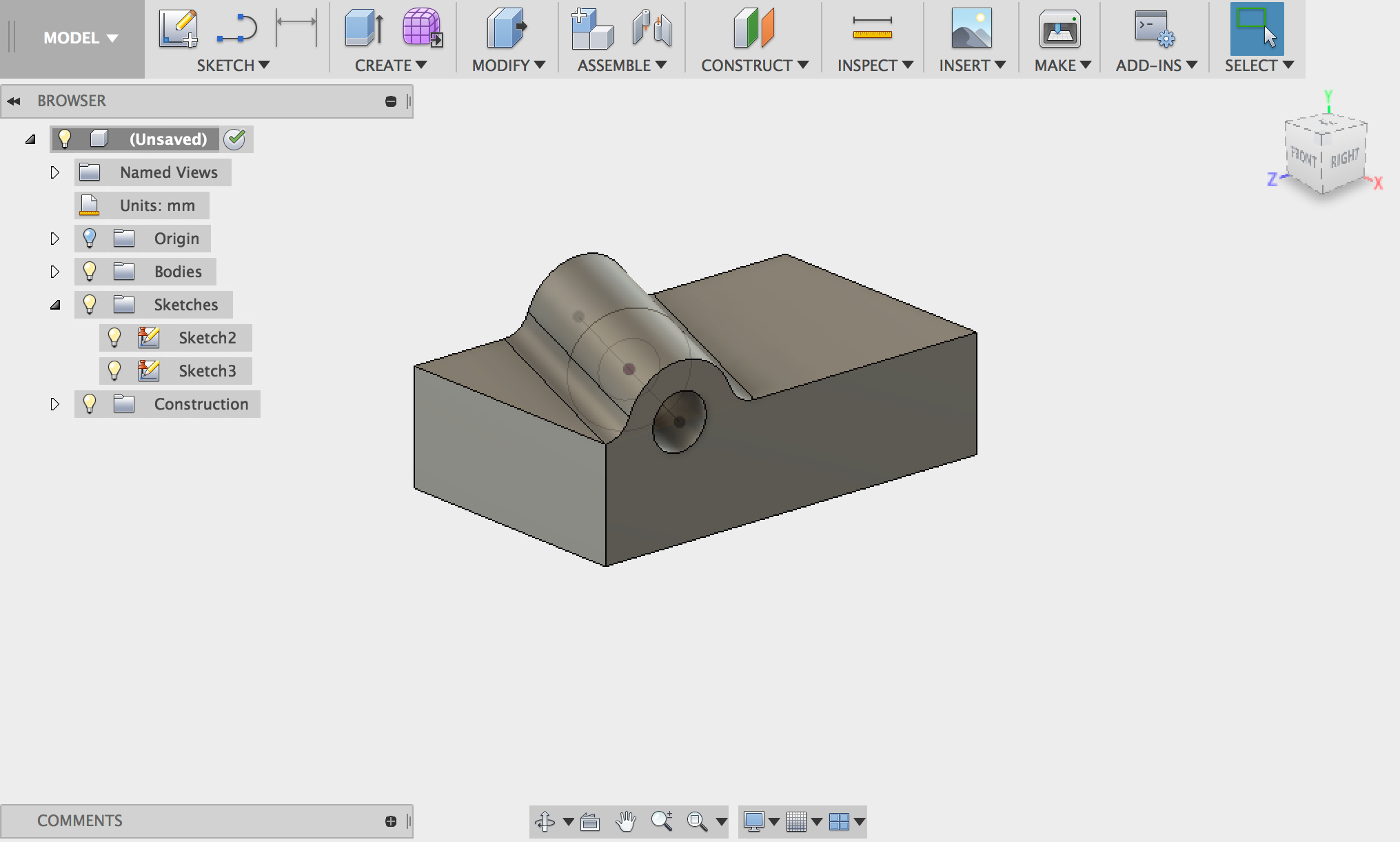
- Select a box from under the Create Menu:

- Select the plane you want to work on:

- Click the origin then either pull or type in your dimension:

- Press tab to type in the other dimension:

- Set the height of your box:

- Type L to select line and select the top of your box:

- draw a diagonal line across the top of the box:

- Type d for dimension and click on the two points:

- Drag out the dimension:

- Set the dimension:

- Type d again to reselect the dimension tool. Click on the two lines to find the angle:

- Set your angle:

- Stop the sketch:

- Under the Construction Plane menu select Plane on Path:

- Select the line to be your path:

- If you move the plane to one end of the path, the value is 1:

- If you move the plane to the other end of the path, the value is 0:

- Set the location of the plane to the middle of the path:

- Type c for Circle and click on the Construction plane:

- Create a circle:

- Create a nested circle:

- Stop the sketch:

- Type e for extrusion and select both circles for the profile and select Two sides:

- Set the Extent To Object:

- Select the side of the object to set the object:

- Make sure operation is set to Join:

- select one of these options (whichever makes the cylinder a=end at the side of the box):

- Set the distance of the other side of the circle to To Object:

- Select whichever option that ends the cylinder at the other side of the box. It will be the other option than the one you chose previously:

- Complete the extrusion:

- Your box should look like this:

- Turn on the sketch. Type e and select the smaller circle:

- Set the operation to cut and pull out both sides:

- Select fillet and add a fillet to both edges where the cylinder meets the top plane:

Extruding text or curve onto a curved surface
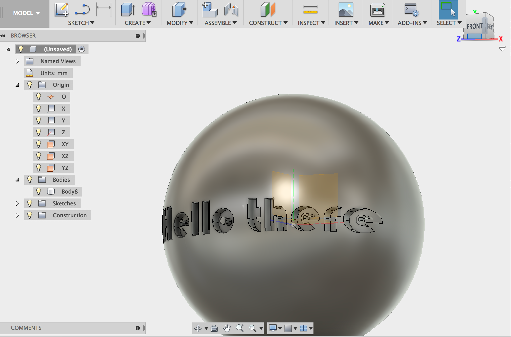
- Create your curved surface:

- Select your ground plane:

- Set your objects size:

- Create an Offset Plane:

- Move the plane out:

- Select text from the Sketch menu:

- Add you text and place it:

- Extrude the text to Object:

- Set your curved surface as the object:

- Set operation to New Body:

- Move the extruded text into the curved surface:


- Now you need to subtract the text. Select Combine:

- Set the extruded text to be the tool body and make sure Cut is selected:

Extrude (E) or PushPull (Q)
- Extrude works on sketch profiles and/or planar faces.
- PushPull works on faces and/or edges
- Invoking PushPull on a sketch profile turns it into an Extrude command
- Invoking PushPull on an edge turns it into a Fillet command
- PushPull has 3 offset modes (1. Automatic, 2. Modify Existing, 3. New) Modify Existing, modifies a previous feature.
- Bodies created are the same whether using Extrude or PushPull. The difference will be in the timeline and the feature type you create.
PressPull maintains the same curved surface you want to modify. So if you wanted to enlarge a hole, you would use PressPull.
Exercises
- In most CAD programs a Wedge is a primitive shape that comes with the basic set. Fusion 360 does not include a Wedge. but you can create your own wedges using extrude.
- In most CAD programs a Pyramid is a primitive shape that comes with the basic set. Fusion 360 does not include a Pyramid. but you can create your own pyramids using polygons and extrude where you specify the angle to taper.
Loft
The LOFT command creates solids based on a series of cross-sectional profiles. Solids can be created by lofting just the cross sections or the cross sections with a path. You can even loft to a point (this would be how you would create a pyramid). Make sure that you select each profile in the order that you want to loft them.
One handy way for controlling where your profile are is to create a sketch that hold a series of lines. You will then create construction planes at an angle with the line, setting the angle to 90 then sketching your profiles on each construction plane. Placing the lines in a sketch will make adjusting distances of the profiles easier.
- Create a sketch and select your plane:

- Select Line or type l and draw your vertical line:

- Draw perpendicular lines where you want your profiles to be:

- Stop your sketch:

- Create Construction planes by selecting Plane at angle:

- Set the angle to 90°:

- Create all your planes:

- Create your profiles on your planes:

- Select Loft and click on your profiles in the order you would like to loft:

- Adjust the location of your lines to change the distance between your profiles:

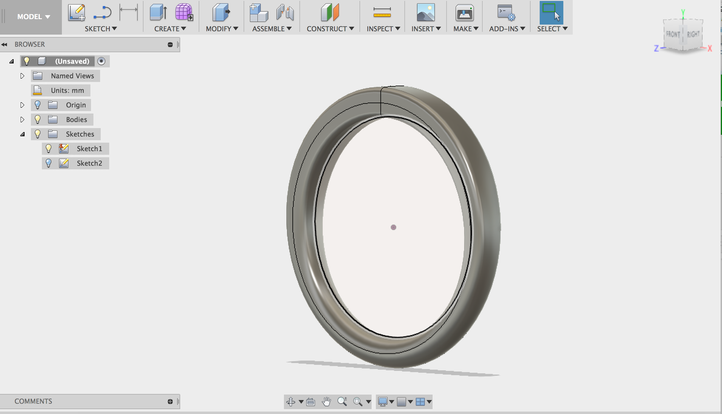
- Create a new sketch and select the XY plane:

- Create a circle the diameter of your finger:

- Stop the Sketch:

- Create a new sketch:

- Select the plane that is perpendicular to the XY plane:

- Select Intersect:

- Click on the circle and then click on OK:

- Draw a rectangle:

- Select midpoint:

- select the bottom of the rectangle:

- Select just the intersection point:


- Set the dimension of the rectangle:

- Select fillet:

- Click on two perpendicular lines and set the radius for the fillet:

- After you have pressed RETURN and set the dimension, you can double click on it to reopen it, then roll the cursor over the left grey tab, this will tell you which dimension this is )in this case it is the fourth dimension or d4):

- Create the next fillet and instead of entering a number, enter d4:

- Continue creating fillets and setting to d4 until each corner of the rectangle is filleted:

- Select a 2 point circle:

- Draw a circle from the bottom intersection point:

- Select the Line or type L:

- Draw a line from the intersection across the circle:

- Click on Horizontal/Vertical constraint:

- Click on the line. This will ensure that this line remains vertical:

- Select the line again:

- CTRL+click on the line and set the line to be a construction line:

- Find the name of the vertical dim of your rectangle:

- Set the diameter of the circle to that dimension:

- Stop the sketch:

- Change the view by clicking on the home option:

- Select Loft:

- Click on the rectangle:

- Click on the small circle:

- Set the guide type to centerline:

- Click on the large circle:

- Click on close to complete the ring:

- CTLR+click on the large circle sketch and Edit Sketch:

- Adjust your ring :

Exercises
- Create a pyramid with loft
- Create your own tent

- Create a sketch:

- Select the plane:

- Select Polygon:

- Set your diameter and number of sides:

- Select horizontal constraint:

- Click on one of your polygon's sides:

- Stop the sketch:

- Create a new sketch and select the plane that is perpendicular to the polygon:

- Select Line or type l. Draw a vertical line:

- Stop the sketch:

- Select Loft:

- Click on the Polygon. This will be your first profile:

- Click on t:

- Change from Sharp to Point Tangent:

- Use the arrow to adjust the weight or enter a number in the dialog box:


- Create a sketch:
- Create a more complex ring:
example:
Shell
Shell is how you create hollow objects.
- Create a cylinder:

- Select Split Face:

- You could split the entire object or just a single face:

- Select the plane as the splitting tool:

- Select the draft tool:

- Select the vertical plane (perpendicular to the face you want to rotae):

- Select the face:

- Use the rotate gizmo to rotate the face or enter a value for the angle. If both faces move de-select Tangent Chain:

- Repeat process for other face:

- Select Shell:

- Click on a face and set the wall thickness:

- You can also select multiple faces:

Slice
- Create a box:

- Slect the XY plane:

- Set the xY dimensions of your box by dragging:

- Set the height of your box by dragging up:

- Create a Construction Plane by selecting Midplane:

- Seelct the top face of your box:

- Select the bottom face of your box:

- Select Split Body:

- Set your box to be the body to split:

- Set the construction plane to be the splitting tool:

- Create a Construction Plane by select Plane at Angle:

- Select an edge and an angle:

- Split the body by setting the box to be the body and the new construction plane to be the splitting tool:

- Create a Construction Plane by selecting Plane Through Two Edges:

- Select one edge:

- Select another edge (these edges need to be able to create a plane):


- Split the body by setting the box to be the body and the new construction plane to be the splitting tool:

- Create a Construction Plane by selecting Plane Through Three Points:

- Select three points that can describe a plane. Then split the body by setting the box to be the body and the new construction plane to be the splitting tool:


- Select Create Sketch and click on the front of your box:

- Select the spline tool:

- Draw a curve on the front of your box:

- Stop the sketch:

- Create a Construction Plane by selecting Plane Along Path:

- Click on the curve:

- Move the plane to the beginning of the curve. You should see the value 0:

- Move the plane to the end of the curve. You should see the value 1:

- Move the plane to where you want it:

- Select Split Face:

- Select the faces to split. Set the cutting tool to the new construction plane:

- Notice that only the face was split:

- Create a box. Create a sketch and select the front of your box:

- Sketch a spline on the face:

- Stop the sketch:

- Select Split Body:

- Set the box to be the body to split:

- Set the curve as the Splitting tool:

- Enable Extend Splitting tool:

- Hide a body to show your cut:

Boolean Operations (Union, Intersect, Subtract/Difference)
Boolean operations are a structured way to combine solid shapes. The principle comes from set theory, where essentially the points in each shape are combined using logic operators like And, Or, and Not. In the world of 3D modeling, these terms are usually some variation of Union, Intersection and Difference or Subtraction.
Boolean operations allow you to form more complex shapes by combining simpler shapes. Boolean operators are widely used in B-Rep-based CAD solid modellers like Fusion 360 or Solidworks.
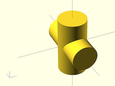
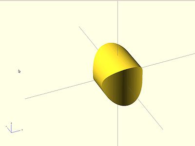
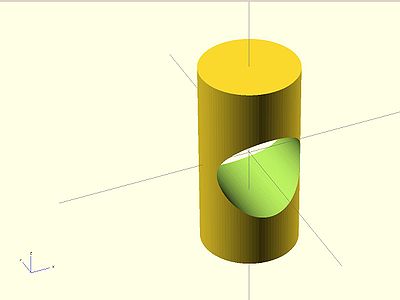
You will find all the Boolean Operations (Join, Intersect and Cut) under the Modify→Combine Command.
Fusion 360 has another way to make a hole. Create a simple, counterbore, or countersunk drilled hole with the Hole command. The Hole command creates a hole feature on the face of an existing solid. Using the Thread command, you can create matching threads on a cylinder. Using the hole command, a hole can be placed directly on the face of the cylinder with no additional work planes or sketches required. Fusion 360 selects the quadrant of the cylinder that is closest to where your mouse is at the time of clicking on the face. From there you can add a dimension to offset the hole from the end of the cylinder. You can also rotate the hole on the face using hole a center point rotation angle.
Exercises
- Create a Lego brick:


Image from Instructables - Create a Coin Trap
Source:McMasterCarr-into-Fusion360
Extras!
Replace Face
Replace Face allows you to replace one flat face with a curved surface: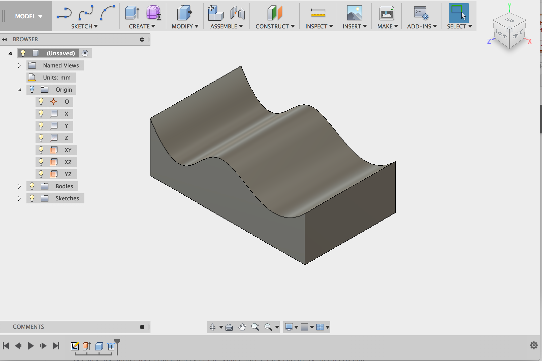
- One the Patch Workspace:

- Select Create Sketch:

- Select spline and draw a curve:

- Stop Sketch:

- Select Extrude :

- Extrdue your surface:

- Select the Model Workspace:

- Selecte Create→Box:

- Select the plane to work on:

- Set your box size so that the curved surface extends beyond the bottom plane:

- Create depth:

- Select your curved surface:

- Select Replace Face:

- Click on the top plane of the box:

McMaster Carr
There is a direct link to McMaster-Carr, a private, family-owned supplier to industrial and commercial facilities worldwide, right inside of Fusion 360. McMaster maintains over 555,000 products in a catalog offering a variety of mechanical, electrical, plumbing, and utility hardware not usually located from a single source and many files have associated CAD files that you can use in your projects.The objective is to use this part in your model:
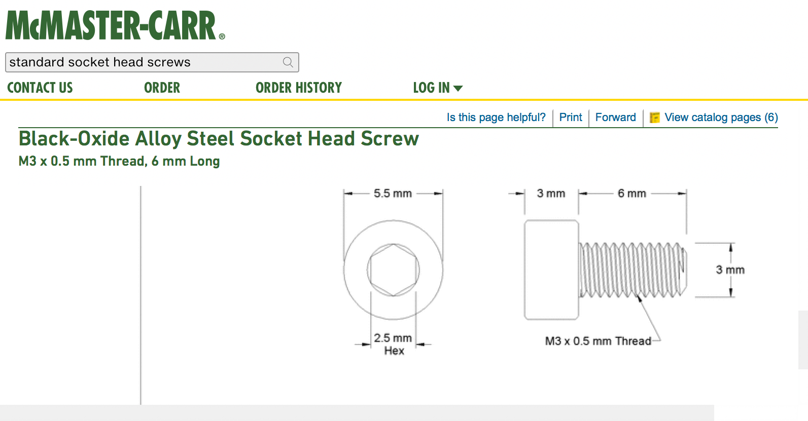 Fusion allows you to import parts directly from McMaster Carr
- Start with a box or a series of boxes. Select hole and create a hole with a counterbore:

- Select Pattern and Rectangular Pattern:

- Place the copies of the hole feature appropriately:


- Select Insert :

- Select the type of hardware to import:

- Refine your selection:

- Keep refining:

- Continue refining:

- Continue refining:

- Continue refining:

- Select Product Detail:

- Select the file type and click on Save:

- You have two options for placing the imported component where you want it:
MOVE:- CTRL +click and select MOVE, then translate the component to where you want it:

- Select Assemble→Joint:

- Select the face on the component:

- Select the matching face of where you want to place it. Press RETURN:

- CTRL +click and select MOVE, then translate the component to where you want it:
- Type a and select a texture. Drag the texture over your component:

Threads
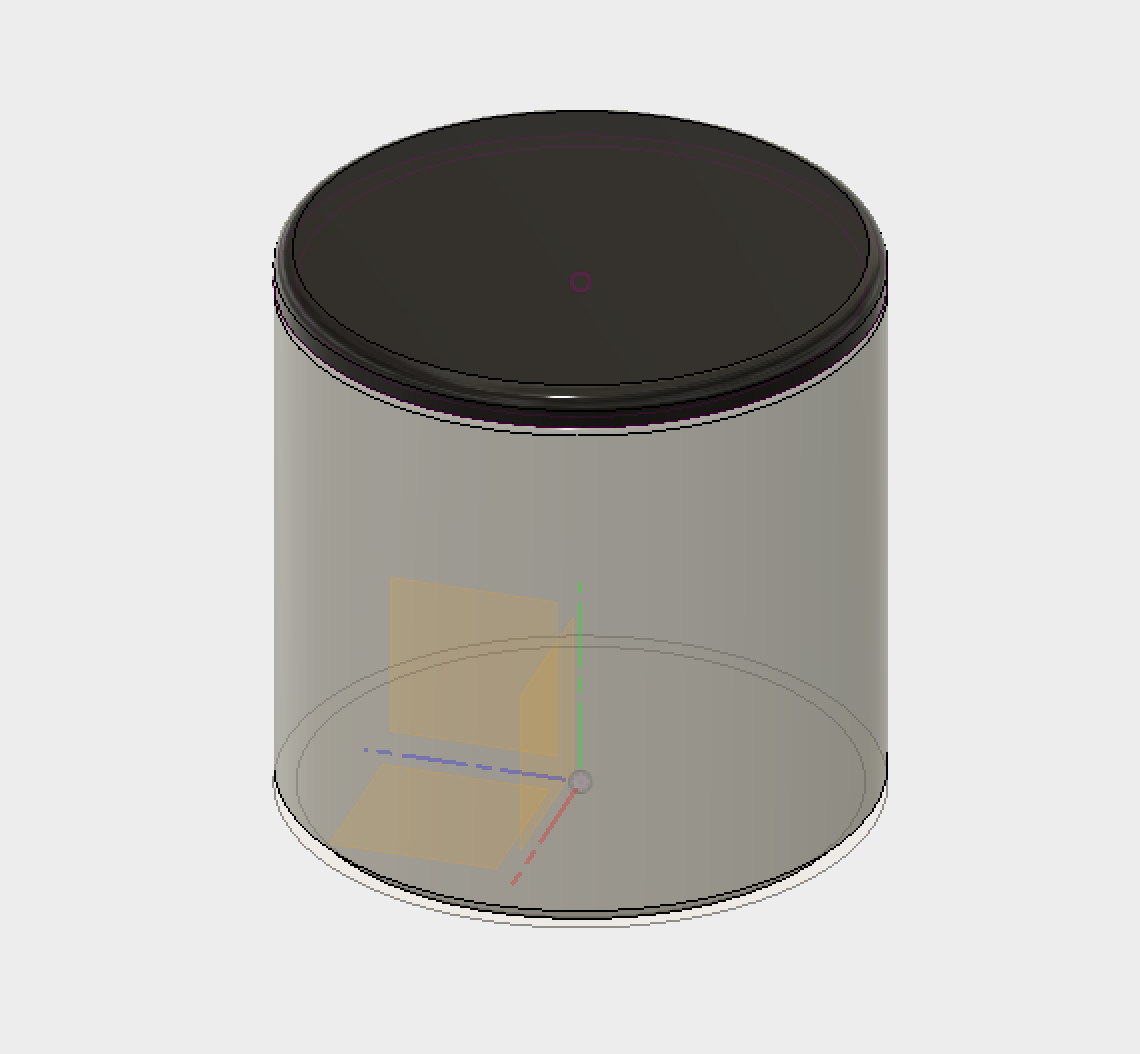
- Create a sketch:

- Select a plane to work on:

- Create a diameter of a circle:

- Create an offset for the wall thickness:

- Extrude the walls of the cylinder:

- Select threads:

- Set the parameters of the threads. Make sure you select modeled:

- Create a construction plane at the top of the cylinder:

- Select project:

- Click on both circles:

- Stop the sketch and extrude up:

- Extrude down:

- Select threads:

- Apply the threads:

- Apply a fillet:

- Apply a fillet and a chamfer:

Fillet
- Create a new Sketch:

- Select the XZ plane
- Select Rectangle and draw a rectangle where you set the x and y dimensions:

- Stop the Sketch:

- Select Extrude or type e and extrude the sketch:

- Create a new sketch:

- Select the top of the box, then select the Rectangle or type t and make a rectangle starting from the top left corner of the box. Dimension the rectangle:

- Stop the sketch:

- Select Extrude or type e and extrude the sketch:

- Select Pattern→Rectangular Pattern:

- Set Pattern Type to Feature:

- Select the feature by clicking on the extrude icon in the timeline:

- Click on the axis to select the direction:

- Set the number of objects you want and click OK:


- Select Change Parameters:

- Open/reveal the parameters:

- Create your own parameter by clicking on the green plus icon. Call the first one Length and set it to some value:

- Now set the d2 Model Parameter to your new named User Parameter :

- Create another User Parameter. Call this one Distance and set it to a value:

- Now set the USpaceDistance Model Parameter to your Distance Parameter :

- Create another User Parameter. Call this one Width and set it to a value and set d6 Model Parameter to your Width Parameter:

- Create another User Parameter, but this time click on Unit to change what Unit you will use. Select No Units:

- Call this User Parameter Count:

- Set a number and add a comment so that you know what this parameter refers to:

- Now set the UCount Model Parameter to your Count Parameter:

- You can now use a formula to control how your model behaves:

- Update your User Parameters and notice the change:

- Close the Parameters window and select Rule Fillet:

- Set the dialog box so that you are using Against Features:

- Set the Input to be the last extrude and pattern icons. (Use the timeline to select them) :

- Set Against Features to the first extrusion (Use the timeline to select):

- Set the fillet value:

- Notice that All is selected and you see the fillets and the rounds:

- See what happens when you select All Fillets:

- See what happens when you select All Rounds:

- Set the dialog box so that you only have fillets:

- Open change parameters and change a User Parameter. Then click OK:

- Select all the top edges by Shift+clicking:

- Ctrl click on the workspace and select Create Selection Set:

- Click on Fillet or type f. Now click on the selection set:

- Set the fillet radius:

Chamfer
FILLET and CHAMFER are commands that modify edges in sketches or in bodies. A Chamfer is basically a beveled edge.
Exercise
Phonohorn
Keyboard Shortcuts
| Command | Windows | Mac |
|---|---|---|
| Undo | Ctrl + Z | Command + Z |
| Redo | Ctrl + Y | Command + Y |
| Copy | Ctrl + C | Command + C |
| Paste | Ctrl + V | Command + V |
| Cut | Ctrl + X | Command + X |
| Sculpt Workspace Selection | Windows | Mac |
|---|---|---|
| Grow selection | Shift + Up arrow | Shift + Up arrow |
| Shrink selection | Shift + Down arrow | Shift + Down arrow |
| Loop selection | Alt + P | Control + P |
| Loop grow selection | Alt + O | Control + O |
| Ring selection | Alt + L | Control + L |
| Ring grow selection | Alt + K | Control + K |
| Ring shrink selection | Alt + J | Control + J |
| Previous U | Alt + Left arrow | Control + Command + Left arrow |
| Next U | Alt + Right arrow | Control + Command + Right arrow |
| Previous V | Alt + Down arrow | Control + Command + Down arrow |
| Next V | Alt + Up arrow | Control + Command + Up arrow |
| Range selection | Alt + M | CTRL + M |
| Invert selection | Alt + N | CTRL + N |
| Toggle box mode | Ctrl + 1 | Ctrl + 1 |
| Toggle control frame mode | Ctrl + 2 | Ctrl + 2 |
| Toggle smooth mode | Ctrl + 3 | Ctrl + 3 |
| Select edge ring | Double-click an edge | Double-click an edge |
| Select face ring | Select two faces then double-click a third face | Select two faces then double-click a third face |
| Edit Form Command | Windows | Mac |
|---|---|---|
| Add geometry | Alt + Drag | Option + Drag |
| Add geometry and keep creases | Alt + Ctrl + Drag | Option + Command + Drag |
