Saint Ann's Summer Workshop 2016
Day 1
- Stretches (9:00-9:15) (wah, zip zap zoom, Name game (bang), pass the clap)
- Introduction Pulleys (9:15-9:30)
-
Pulleybot (9:30-11:20)
-
Introduction to AutoCAD (11:30-12:00)
-
Pulleybot Challenge (1:00-2:00)
- Gumball Capsule challenge (1:00-2:45)
-
Exporting, Slicing and Printing (2:00-3:00)
- Cleanup (2:50-3:00)
Day 2
More Pulleys
- Stretches (9:00-9:15)
- Introduction (9:15-9:30)
- Modeling (9:30-11:00)
- Exporting, Slicing and Printing(11:00-12:00)
- Animation Intro (11:00-11:15)
- Flipbook Kit (11:00-2:50)
- Cleanup (2:50-3:00)
The Truth about 3D Printing
We're lucky to have access to this relatively low cost technology which allows us to create forms that can't be produced with others tools, and allows us to translate ideas into a tangible objects with ease. But be aware that desktop 3D printing is still in its infancy. The quality of prints gets better with each new printer release, the build volumne is restricted to machine size, and build times are long.So, if you have a limited time, what should you do?
Instead of printing every part of your design, look for what needs to be printed and look for what could be used to acheive the same results.
Today's project will be a simple motorized car. It will use a battery, a motor, a switch and an O-ring pulley. But instead of printing all the parts, we're going to combine 3D printing with some parts that can be purchased in a hardware store or office supply store.
Non-printed Parts
Parts
- switch
- 9V battery
- 9V battery connector
- 22 awg wire
- Pololu Micro Metal Gearmotor 298:1 or 1000:1 or similar
- Zip tie
- Balloon
- O-ring -size 229
- 2 100mm carbon rods
- 4 Screw Eye Rings
Printed Parts
Parts
- chassis
- 2 pulleys
- 6 stoppers
Introduction
Animation can be thought of as change over time. In the simplest sense, animation is a series of still images displayed sequentially. If the rate of change between images, commonly called the frame rate, is fast enough, our brains can't detect the transitions, and you see fluid motion. This effect is referred to as persistence of vision.Types of change
- location
- orientation
- size
- color
Frame stats
Most animation is still produced for film and tv. Film is projected at 24 frames per second (fps). Animation looks just as good at 12 fps. The practice of animating 12 fps is called animating "on twos", and the practice of animating 24 fps is called animating "on ones." In Japan, animators use 8 fps and animate on the threes.
When working on twos animators usually number their frames with odd numbers. 1,3,5 and so on. Frame one is shot twice, frame two is shot twice, etc. If a point in the scene demands a fast action such as a punch or a shake, then the scene can be switched to ones at that point.
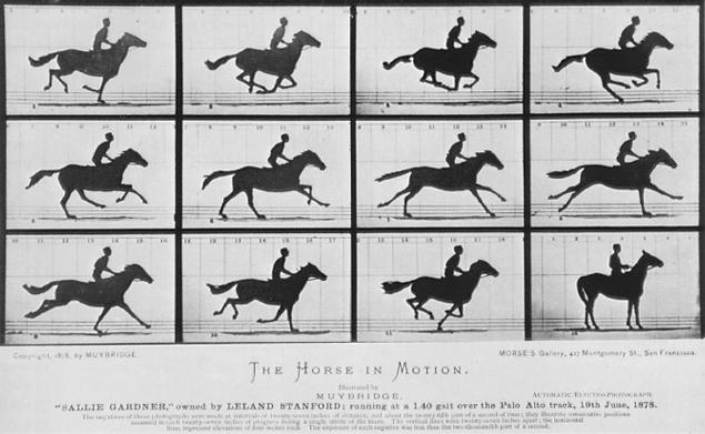
Eadweard Muybridge
On June 15, 1878, in Palo Alto, California, Eadweard Muybridge photographed the first successful serial images of fast motion.The subject of these photographs was the trotting horse, owned by railroad builder and former governor of California, Leland Stanford. The exercise successfully proved Stanford's theory that during a horse's running stride, there is a moment of time where no hooves are touching the ground.
What began as a topic of unresolvable debate among artists and horse enthusiasts launched a new era in photography:
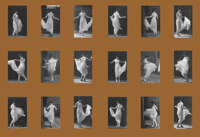
Why is Animation so cool?
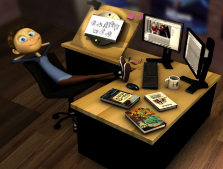
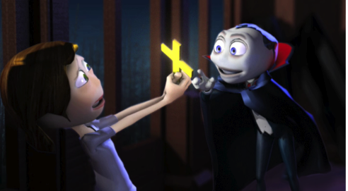
Animation can be used to inspire, educate, inform and entertain us, while showing us the world in a way we didn't perceive it before.By manipulating timing, exaggeration and symbolism, you can create environments that people recognize, and you can use your animation to tell powerful stories in ways that live action can't.



Flipbook Kit
The flipbook kit is based on work by Artists Wendy Marvel and Mark Arnon Rosen.From Mechanical Flipbook
The first flipbook appeared in Birmingham, England in 1868 when the British lithograph printer John Barnes Linnett patented his new invention under the name kineograph, literally "a moving picture". Although the earlier phenakistoscope was able to produce a circular sequence of images, Linnett's kineograph was the world's first type of animation to use a linear sequence of images.
Almost thirty years later, Max Skladanowsky, the early German filmmaker and inventor, also prepared to unveil his own moving photographic images. He and his brother Emil had not yet developed their own film projector, and he exhibited his serial images as a flipbook in 1894. That same year, the American Herman Casler unveiled his new invention, the Mutoscope — a mechanized flipbook that, instead of binding the images as a flipbook, mounted them to a rotating cylinder.
It was Casler's invention that truly captured the public's imagination and his variation of the classic flipbook was a popular attraction well into the 20th century, often appearing in amusement parks and arcades. At the turn of the century, Henry William Short introduced the filoscope, a flipbook that included a small metal holder that made it much easier to flip the pages and see the images come to life.
- Put together the Basic Kit
Choose 1 or more of the following instructions to follow: - Add the motor and pulley:
Open the Adding The Motor instructions and follow the steps.- Start with assembled flipbook:
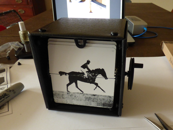
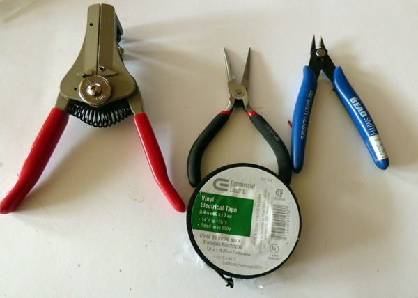
- You will need:
- phillips head screw driver
- pliers
- strippers
- clippers
- electrical tape
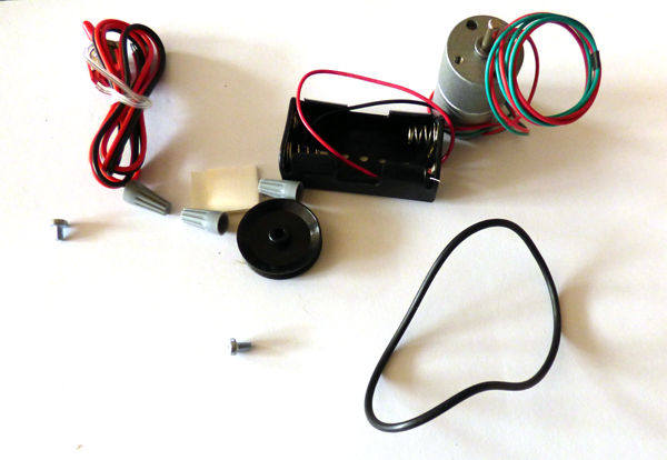
- Open the motor kit:
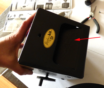
- Carefully punch out flap. (i used a tool to push flap the other way after separating along perforations):
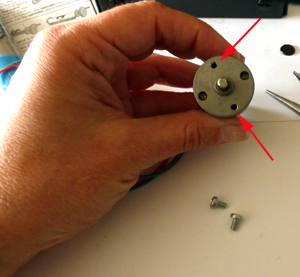
- Find the holes without screws:
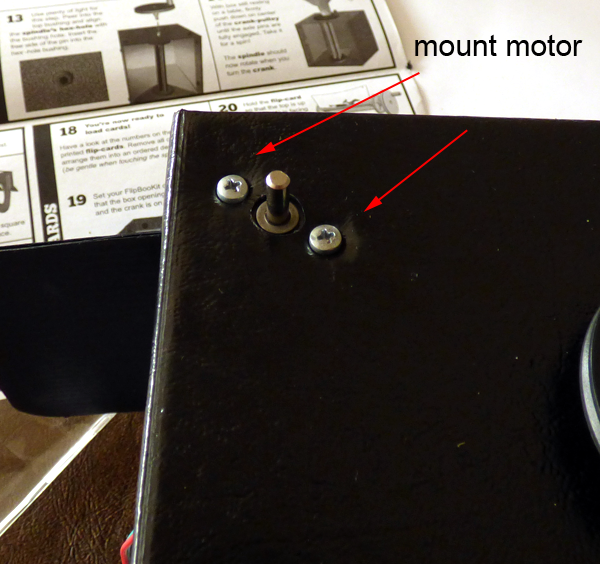
- Mount the motor and place screws in empty holes:
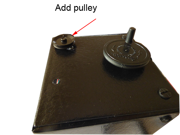
- Add the pulley to the motor shaft:
- Add the o-ring:
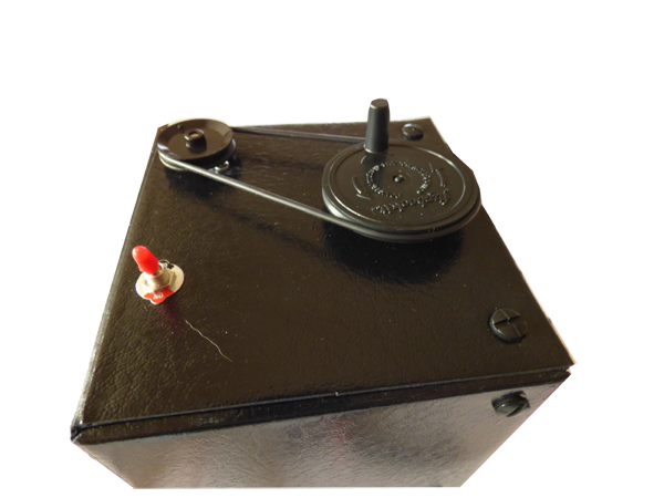
- Instll the switch with ON towards the top:
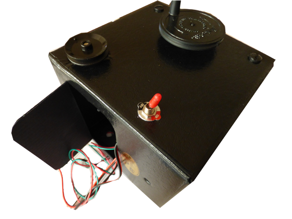
- Add the battery holder with double-sided tape:
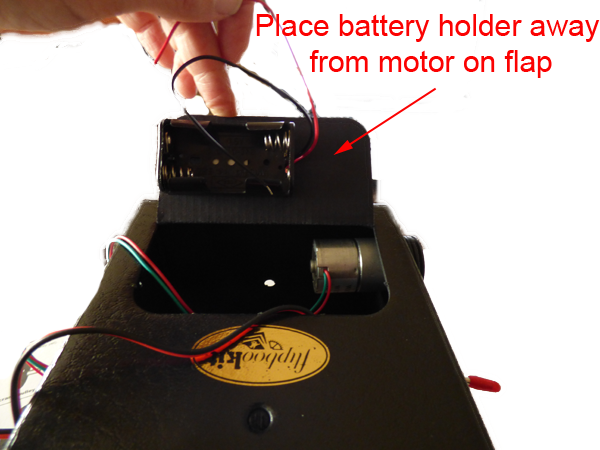
- Trim the wires (about 4 fingers):
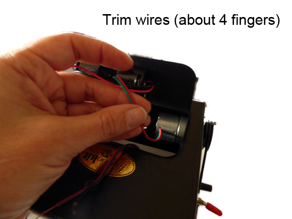
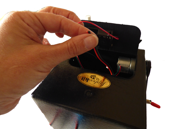
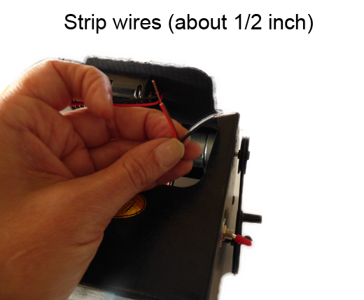
- Strip the wires:
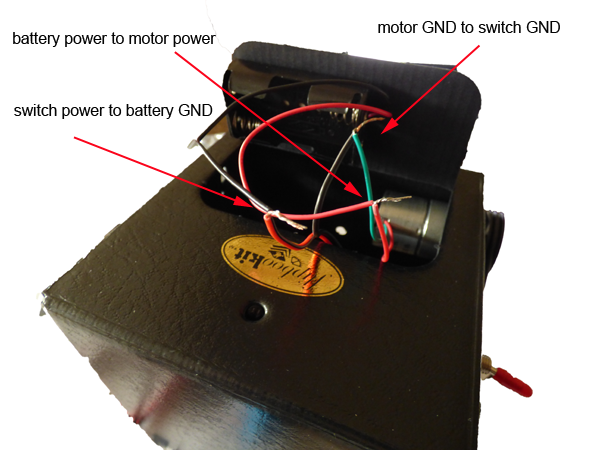
- Make the wire connections:
- Cover exposed wires with electrical tape.
- Add batteries.
- Turn on kit.
- Start with assembled flipbook:
- Create your own animations:
- Watch the video found at how to make your own animation
- Upload video or frames to the Maker Tool
Day 3
Motorbots
- Stretches (9:00-9:15)
- Introduction (9:15-9:30)
- First Circuit (9:30-10:15)
- Second Circuit —Design a 3D printing enclosure (10:15-12:00)
- Makey Makey Go (1:00-2:50)
-
Cleanup (2:50-3:00)
The second Circuit
You have a choice of starting with a presoldered bot or soldering your own: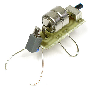
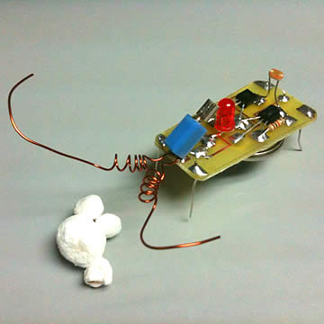
When you design your enclosure remember you need to limit the amount of material (a too heavy encolosure will prevent the bot from moving).
Make sure that the light sensor or the switch is not blocked.
- Sketch out your ideas on paper.
- Can you model your idea? is it printable?
- You can also explore Tinkercad
MakeyMakeyGo
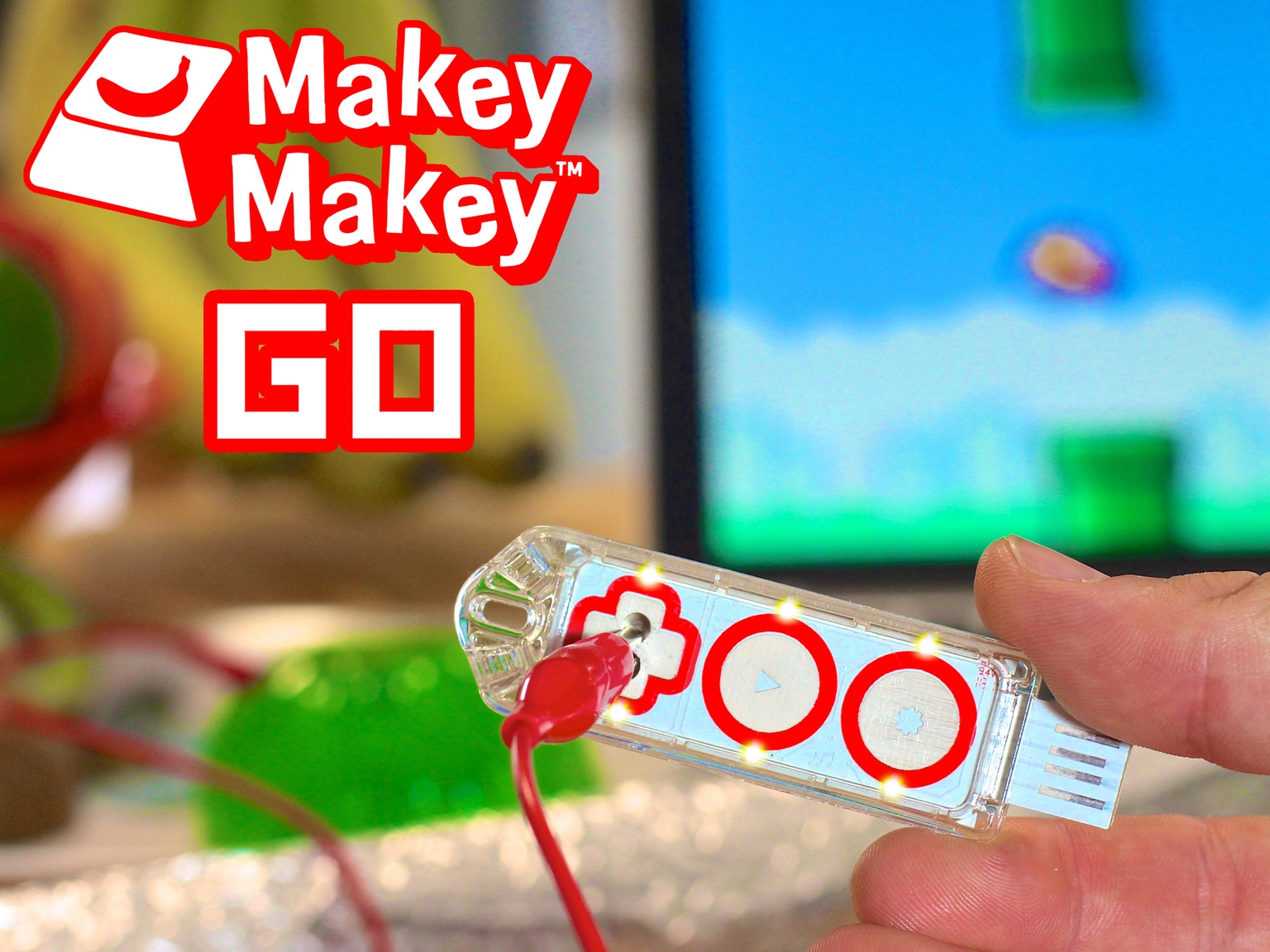
Instructions
- Pick an object
- Open Scratch or another application that responds to a mouse click.
- Plug in your Go
- Connect one end of you alligator clip to the plus on the Go.
- Use the Play button to set the sensitive settings (hold it down for a few seconds).
- Use the set (star) button to toggle between mouse-left click and space key.
- Here is sample scratch code to get 3 different notes from touching the same object:

- Create an interaction.
Introduction
BristleBots are simple and tiny "robots". The BristleBot is one version of a vibrobot, a simple category of robot that is controlled by a single vibrating (eccentric) motor.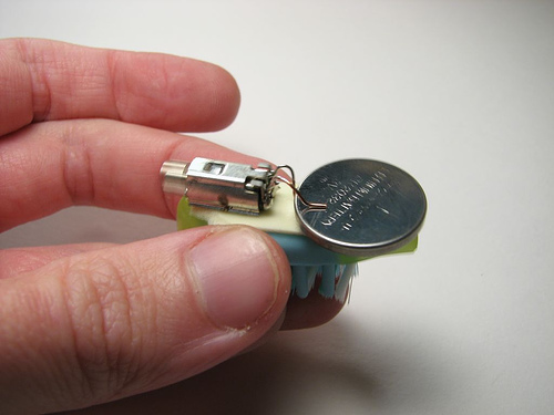
Image from: Evil Mad Scientist
First Circuit
Parts
- toothbrush
- 3V battery
- pager motor or other tiny motor with an unbalanced output shaft
- Small switch
- Double sided tape
- Switch
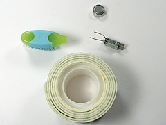
Image from: Evil Mad Scientist
Assembly
- Cut off the handle of the toothbrush
- Solder wire leads to the motor terminals.
- Add a switch (solder to middle lead and toggle lead) .
- Select a battery holder.
- Apply a small piece of double sided tape to the top of the toothbrush robotic platform, which will be used to hold the motor/circuit in place.
- Battery and motor placement, bristle shape (one stray long bristle can interfere with the motion, and motor rotation direction all influence the behavior). Try flipping the battery upside down if you have trouble getting your bot to go straight.
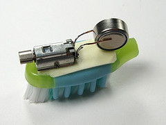
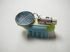
Image from: Evil Mad Scientist
Day 4
Pulleys and Gears
- Stretches (9:00-9:15)
- Introduction Gears (9:15-9:30)
-
gearbot (9:30-11:20)
- Cat Toy (1:00-2:50) or Continue working on Flipbook Kit animations (Maker Tool)
- Cleanup (2:50-3:00)
Cat Toy
Parts
- 3V Red Laser Module
- Push button
- 3V Battery holder
- 3V battery
- 22 awg wire
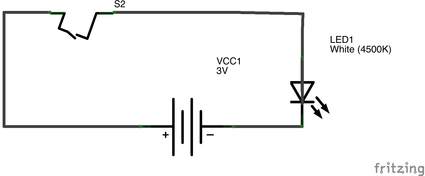
Design a laser beam cat toy that is fun to hold.
Another Circuit
Magnetism can be used to step-up a voltage with a few electronic components./ / Simple Thief
A Joule thief allows you to boost the voltage of a dying battery.
Without the joule thief, you cannot light and led with a 1.5 volt battery
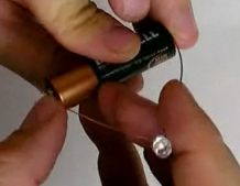
- Get the following parts along with some copper wire:

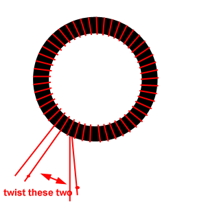
- Clip off 5-6 feet of wire and then fold in half. Twist the top of the folded end
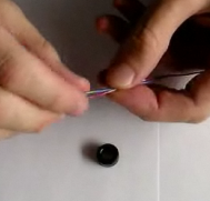
- Make a knot on the top of one of the wires
- Make a knot at the bottom end of the wire with the knot on the top

- Using the loop end wrap the wire around the torroid
- Take one knotted end with a straight end and twist
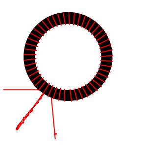
- Take sandpaper and sand off ends
- Use a multimeter to test for continuity
- With soldering iron, tin the ends
- Bend the legs of the transistor
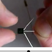
- Transistor:
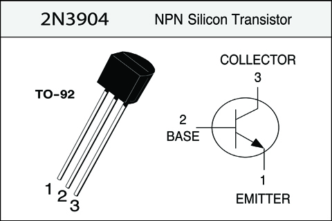
Image from www.ecs.umass.edu/ece
Fold the base of the transistor under and solder it to the resistor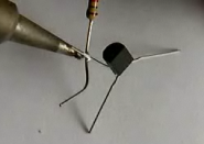
- Take the LED and solder longer leg to the collector

- Solder the shorter side of the led to the emitter
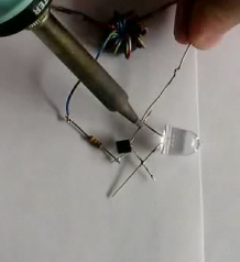
- Solder the resistor to one single lead of the torroid
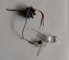
- Solder the other single leg from the torroid to the longer lead of the LED
and the transistor's collector:
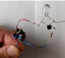
- Cut three inches of wire and strip off both ends
- Solder one end of the wire to the emitter/short end of the LED
- Connect circuit to battery (wire to gnd and double wire from torroid to positive terminal) and let the light shine

So how does it work?
Imagine the condition when the battery is first connected. The transistor is off, but voltage can flow down the left side of the transformer (wound toroid) in the diagram, current limited by the resistor. This turns on the transistor, and a larger amount of current can flow through the other side of the transformer and through the resistor. Because the voltage applied across the LED is well below its forward voltage, no current flows through the LED, and the LED does not yet turn on.
The larger current flowing through the right side of the transformer induces a current in the left side of the transformer that opposes the existing current on the left side-- and the current on the left side quickly drops down to zero. When this happens, the transistor shuts off. With no current flowing in the left side of the transformer, the toroid acts like a simple inductor, which is like a flywheel for current. There is already current flowing though it, which cannot shut off immediately, and the resulting current (flow of electric charge) towards the collector of the shut-off transistor leads to a temporary increase in the voltage at that point, which continues until the voltage exceeds 3 V, at which point the current finds a way out-- through the LED, which lights up as current flows through it.
As the last of the current fades from the toroid, the LED shuts off again, and we again return to the initial state: no current flowing through either side of the toroid transformer. And the process begins again. This whole cycle happens at a typical rate of about 40 kHz, far too fast for you to see the blinking, and the light from the Joule Thief appears to be continuous. This is a simple example of a switching power supply driven by a transformer-coupled oscillator, made of only four components.
As a side note, this is not the most efficient circuit around; it's beauty is that it works with such a low voltage. So, this is a great circuit to use with a dead or dying battery, and less so for use with a brand new battery.
When the battery is connected current flow into the base of the transistor and the voltage across the base and emitter (Vbe) rises and the transistor is switched on. This means that a larger current can now flow through the primary winding and then through the transistor. This generates a magnetic field in the toroid opposite to the field created by the base current through the secondary winding. As soon as the primary current is greater than the secondary current the voltage on the secondary winding reverses switching the transistor off. The magnetic field collapses and the LED is switched on briefly and the whole process starts over again. The cycle repeats 40 000 times a second. Lastly the 1K resistor is there to limit the base current of the transistor.
/ / Cat Burglar
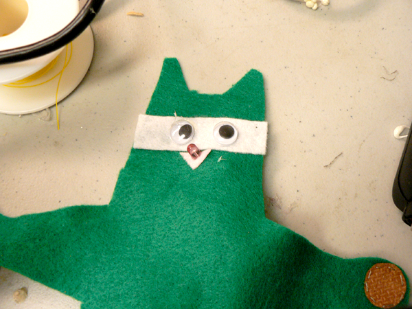
When the cat burglar gets his little paws on a battery his LED nose lights up until all the joules are gone.
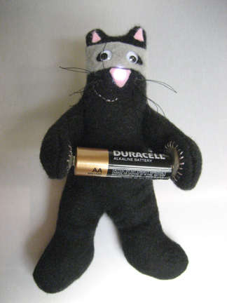
Tools
- Scissors
- Embroidery Needle and Thread
- Soldering iron
- Glue gun
- Wire cutters
- Wire strippers
- Marker
Parts:
- Solid Core Ferrite Suppressors - Mouser - PN 875-28B0500-100
- Magnet wire
- Transistor -2N3904 or 2N2222
- LED
- 1KΩ resistor
- Conductive Fabric
- Felt
- Googlee eyes
- 2 small strong magnets
- Stuffing
- Fabric glue
- Use the template or make your own design. If you make your own design, keep the size the same
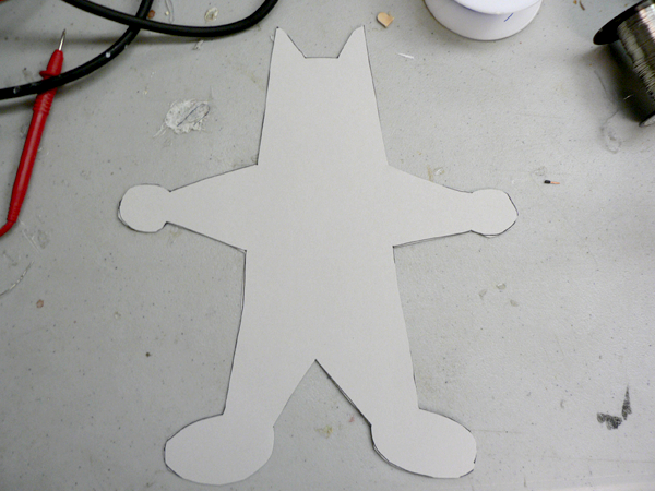
- Cut out two pieces of felt
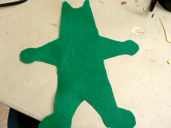
- Cut out holes where the paws are:
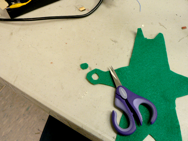
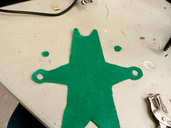
- Use template to cut out conductive fabric for the front and back sides of the paws.
You'll need two fronts (circles) and two backs: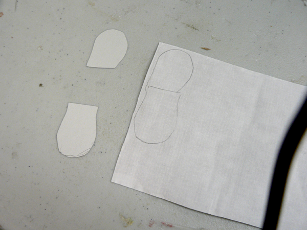
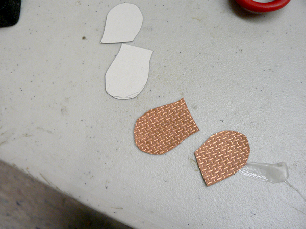
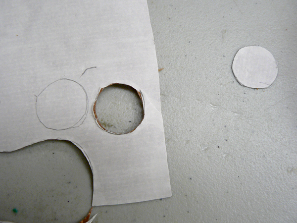
- Cut out your mask and nose
- Peel the paper backing off and place the frons and backs on the the paws. Iron them together
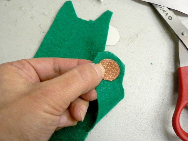
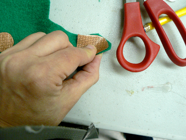
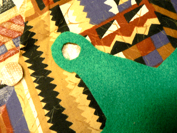

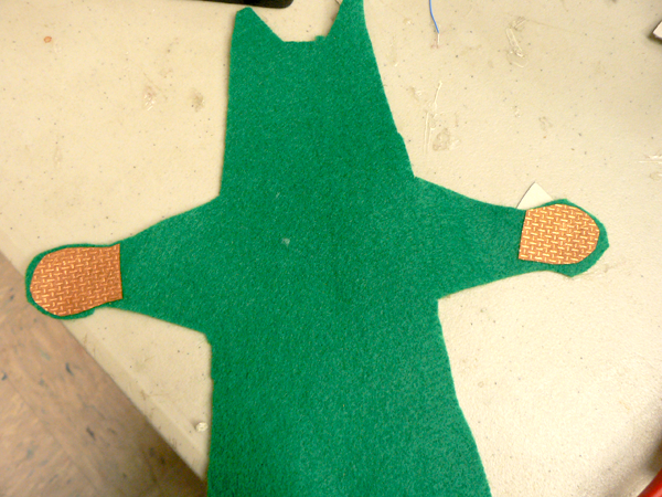
- Iron on the face
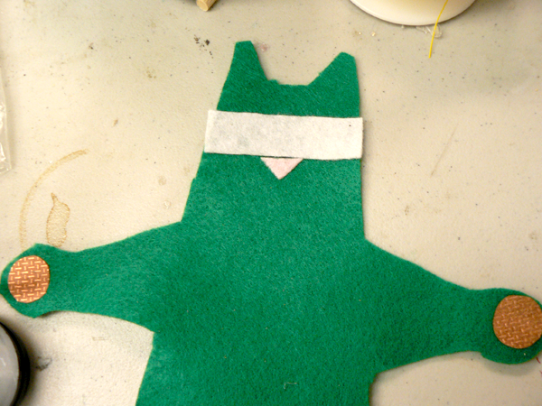
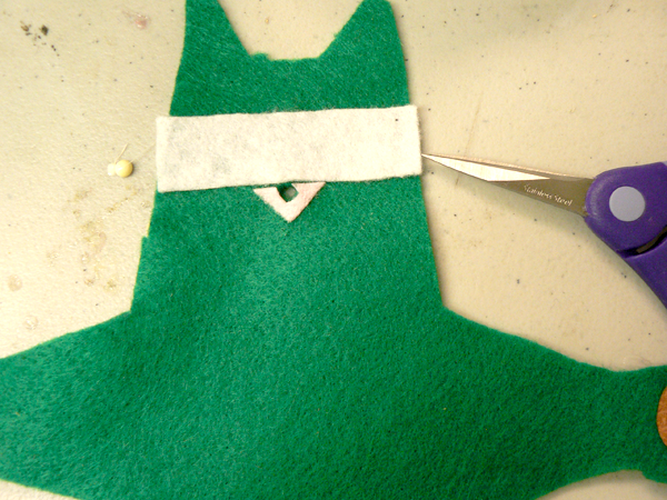
- Cut a hole in the nose-just enough to fit the LED
- Glue magnets to inside of paws. Cover with glue, but don't put glue between magnet and fabric.
Take care to keep the magnets apart during the gluing process—they might break. Make sure the magnets are positioned so that the opposite poles are facing one another. Why? Because when your cat burglar is finished, the paws will clasp together.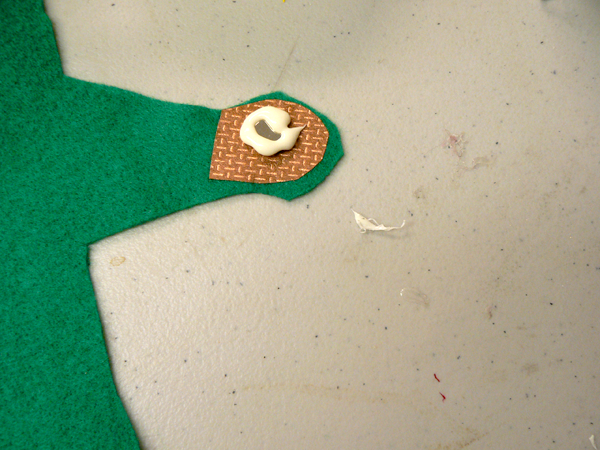
- Stick LED through fabric to create nose
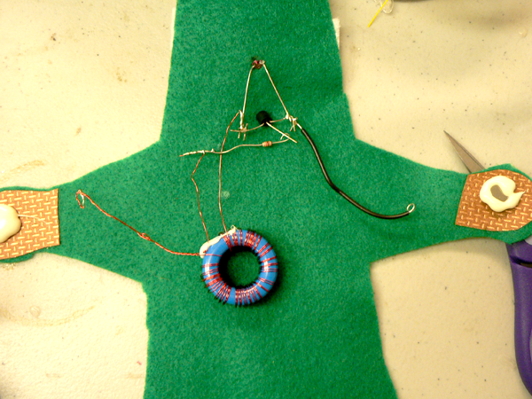
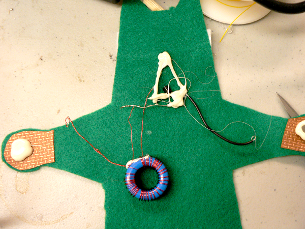
- Glue to fix the thief in place and to also cover wires, preventing short circuits.
- Use conductive thread to sew the twisted strands to the inside paw. Use enough thread to make a good connection. Try not to go through the felt to the front side.
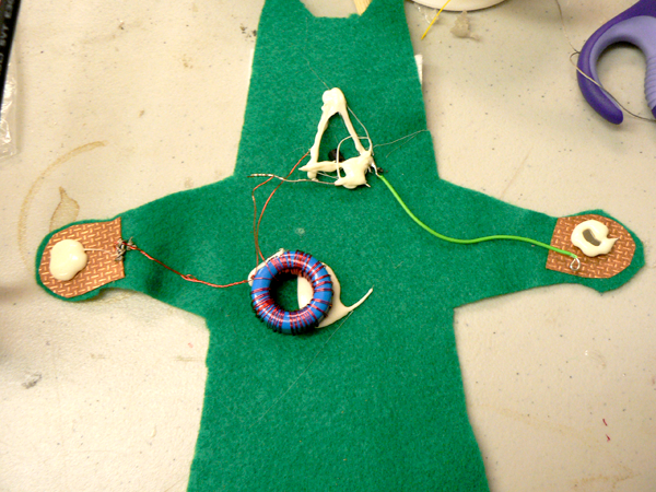
- Sew the other lead of the joule thief (the 3 inch wire) to the other paw.Use enough thread to make a good connection. Try not to go through the felt to the front side:
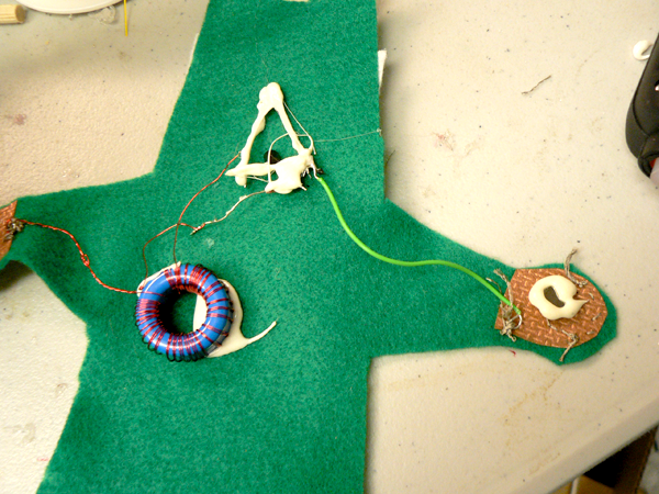
- Sew pads with conductive thread. This will connect the inside to the outside of the paws to complete you circuit. This time, go through the fabric:
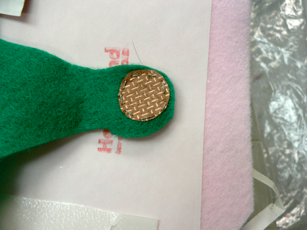
- Sew the back and front together. Before completing, stuff. Then complete the sewing.
When you're stuffing thief, make sure you don't short or break any of the wires. - OPTIONAL:
-
Add a mouth with needle and pink thread.
- Add whiskers
- From scraps of black fabric sew up a tail. Just take two layers of fabric and sew up a kind of crooked tube. Cut the tube out and turn it inside out. Sew the tail to the body.
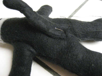
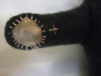
- stitch in a "+" symbol on the positive paw.
- Cut out small triangles from the pink felt and glue them to the ears.
-
Add a mouth with needle and pink thread.
-
Glue on some googlee eyes.
Source: Instructables, Cat Burglar Joule Thief, January 26, 2008
Makezine:The Sympathy Doll
Makezine:Joule Thief
http://blog.makezine.com/archive/2008/01/led_softie.html
http://www.emanator.demon.co.uk/bigclive/joule.htm
Makezine:The Sympathy Doll
Makezine:Joule Thief
http://blog.makezine.com/archive/2008/01/led_softie.html
http://www.emanator.demon.co.uk/bigclive/joule.htm
Day 5
- Stretches (9:00-9:15)
- Design, model and print an enclosure for a flashdrive (9:15-10:30)
- Soft Circuit (10:30-12:00)
- UV Beads (1:00-2:00)
or Finishing up - Upload your files to your flashdrive (2:00-2:30)
- Show and tell (2:30-2:50)
- Clean up (2:50-3:00)
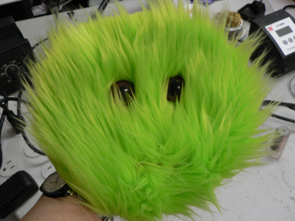
Monster Night Light
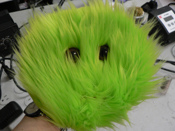
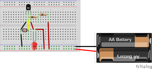
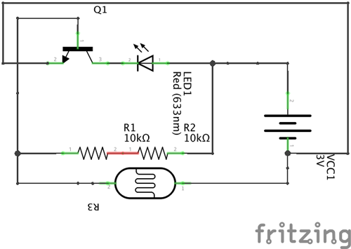
Parts
- 10KΩ resistor
- RED leds
- 10KΩ photocell
- 3V battery
- NPN 3904 transistor

- Test circuit on breadboard
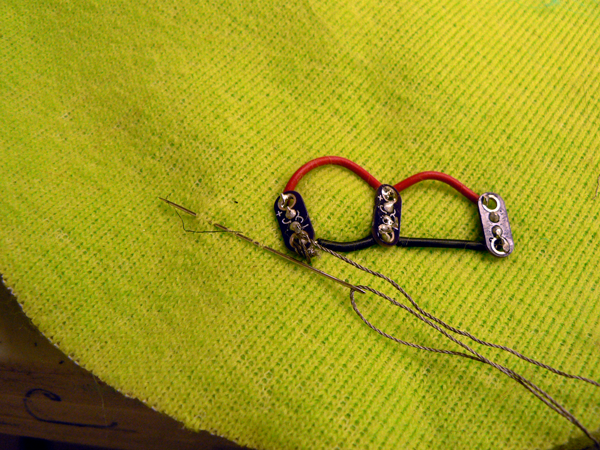
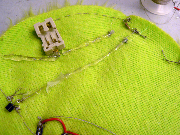
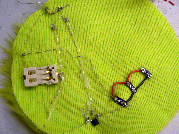
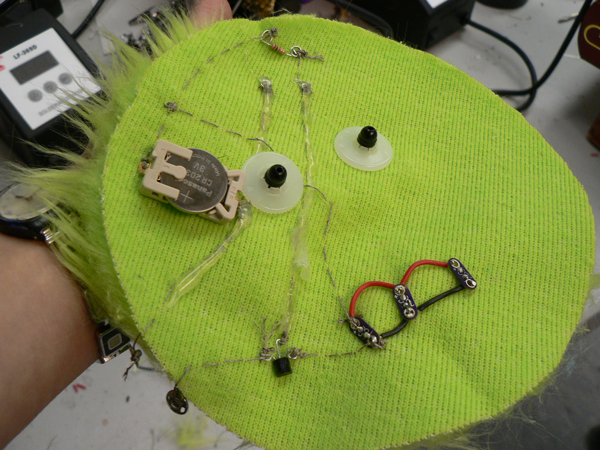
- Push leads of LEDs through fabric and thread them through the PCB boards. Take care to thread the leads correctly. Anode to + and cathode to -
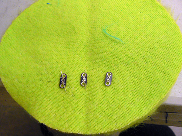
- Solder leads to PCB boards
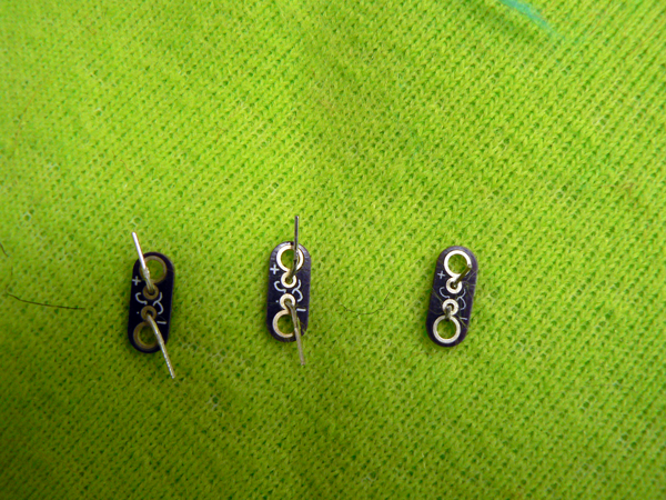
- Solder the power leads together using hook-up wire
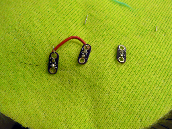
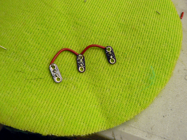
- Solder grounds together using hookup wire
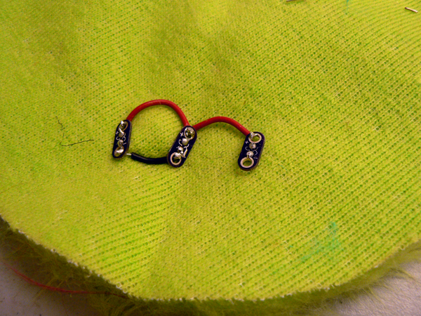
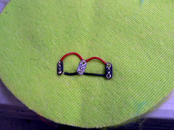
- Connect a GND lead to the collector
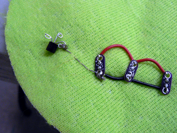
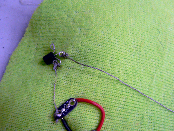
- Stich the leads of the LDR through the fabric. The LDR should be on the front of the fabric
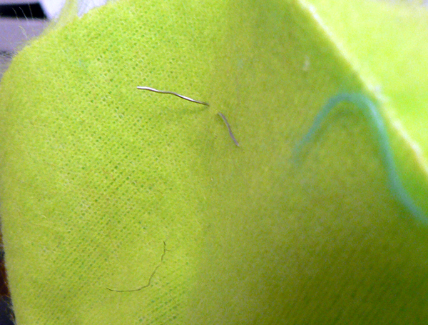
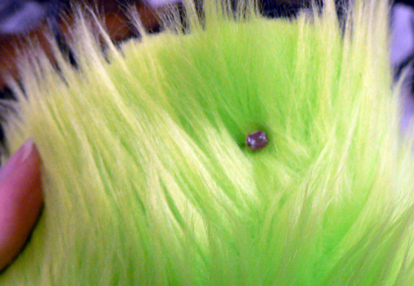
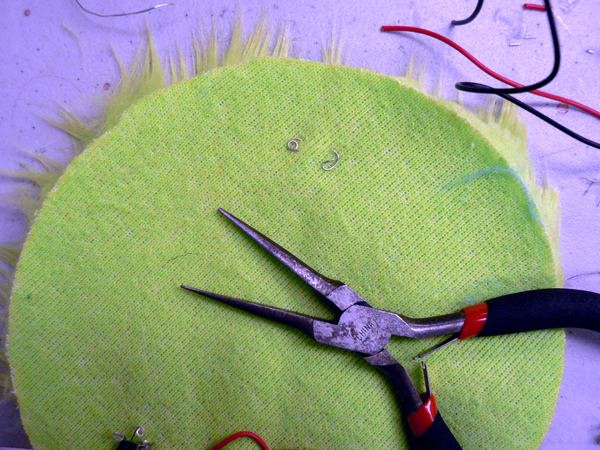
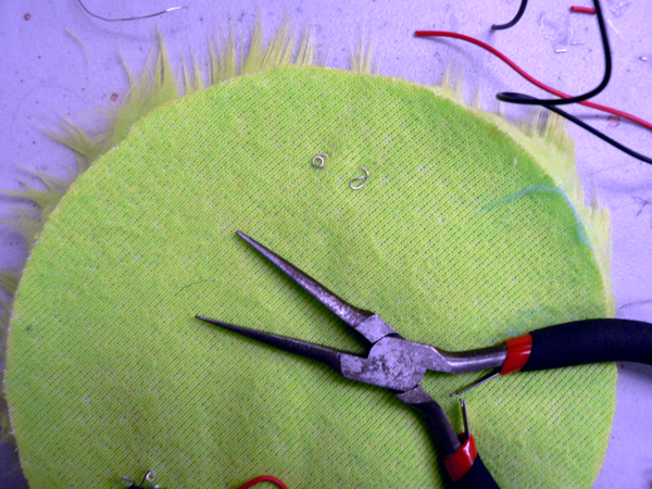
- Use pliers to turn the leads into loops
- Connect the base to one lead of the LDR
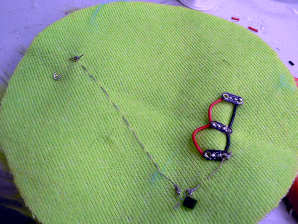
- Prepare the 10K resistor
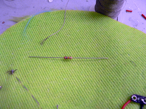
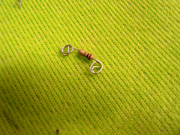
- Connect the LDR to one lead of the 10 resistor
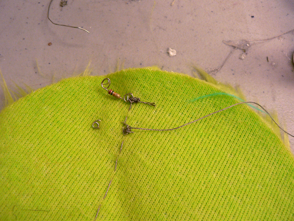
- Connect the other lead of the 10K resistor to the power lead of the coin cell holder
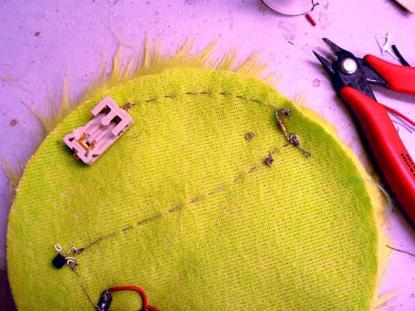
- Connect the emitter to to one half of a snap. Make sure that the snap is outside the circle
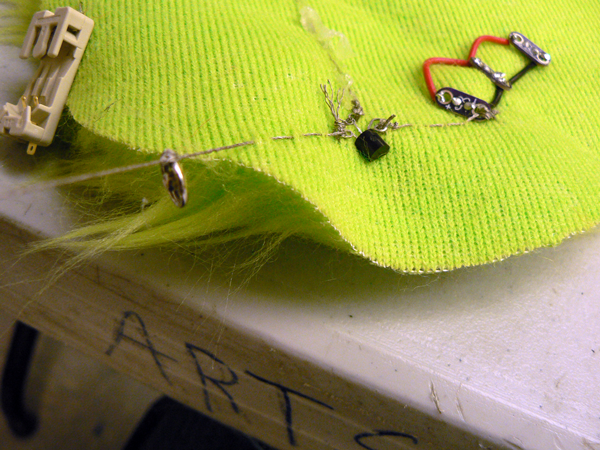
- Cover the thread with hot glue
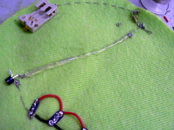
- Connect the other lead of the LDR to the GND lead of the coin cell holder
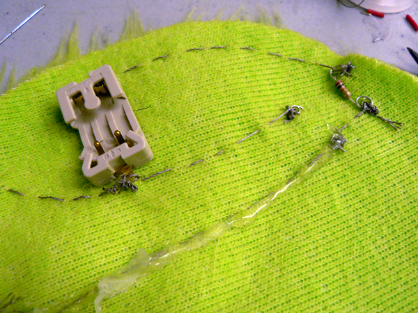
- Connect the GND lead of the coin cell holder to the other side of the snap
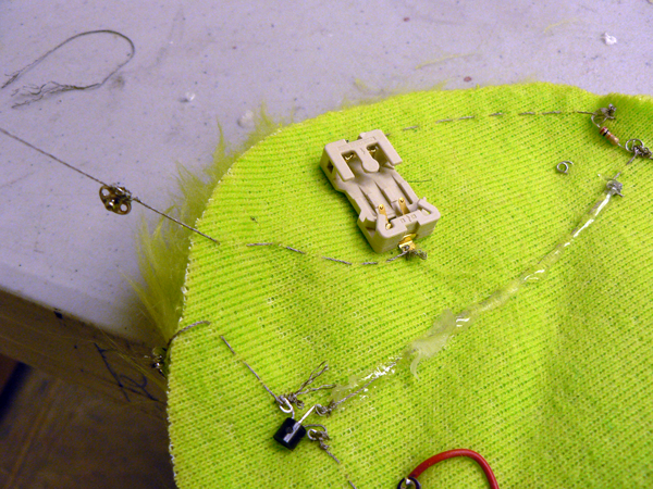
-
-
-
Glow in the dark tape
Photoluminescent or glow-in-the-dark tape absorbs light so that it can emit light in the dark. It will charge from exposure to fluorescent, LED, or daylight/sunlight. Glow tape uses a non-radioactive chemical light source called SPOT-LITE glow film. This film is incorporated into a flexible vinyl film that is laminated to an adhesive backing.Cut strips of glow-in-the-dark. Apply the strips to a piece of paper. "Draw" on the tape with the UV flashlight and then bring your paper into the dark.
UV Beads
Energy Beads or UV Beads change color when exposed to ultraviolet radiation from the sun. The UV-sensitive beads contain a pigment that changes color when exposed to ultraviolet radiation from the sun. Ultraviolet ("UV") light is one of the invisible frequencies of light. Over exposure to it can be harmful to many things including us. The energy beads are not affected by light from light bulbs that do not emit ultraviolet light. The electromagnetic radiation needed to affect change is between 360 and 300 nm in wavelength. This includes the high-energy part of UV Type A (400-320 nm) and the low energy part of UV Type B (320-280 nm). The beads will remain white indoors, when shielded from sunlight.When brought out of the UV, they will fade back to white. The beads can cycle back and forth over 50,000 times.
Create a UV sensing piece of jewelry that will warn the wearer that they ought to bewearing sunscreen.
