July 30, 2015, 9:30am - 1pm
A one day workshop to become familiar with 3D Modeling and Printing topics.
A one day workshop to become familiar with 3D Modeling and Printing topics.
Things to keep in mind
- "The art of teaching is the art of assisting discovery"-Mark Van Doren
- Be patient with yourself when learning something new.
- Think about your ultimate objective. Do you want to:
- Make students responsible for their own learning outcomes.
- Foster important questions in the minds of learners.
- Build cooperative learning opportunities.
- Encourage personal exploration in the pursuit of common learning objectives.
- Develop communication skills through continuous documentation and sharing.
3D printing in education
30 minutes:
- Pair up.
- Take 5 minutes to write down as many polarizing statements about 3D printing and education that you can think of. You don't have to agree with your statements.
- Pick two statements. (one will be your back up and you can use it in case another group uses your first choice).
- Teams go around the room and one at a time, read a statement and people move from one side of the room to the other according to agreement. The center is neutral. People on all sides voice their opinion. See if the crowds move.
What is 3D Printing and Why Teach It
Basic Types
3D PrintersStereolithography (SLA):
A process that works by curing and solidifying successive layers of liquid photopolymer resin using an ultraviolet laser.Industrial:
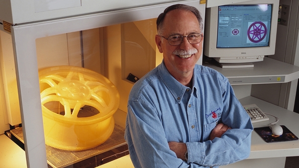
image from:Industry Week
Desktop:
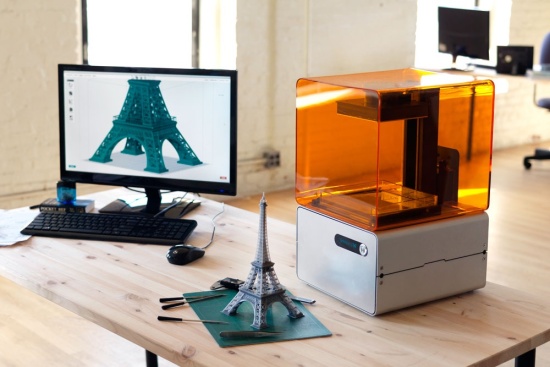
image from:www.3ders.org
Selective Laser Sintering (SLS):
Similar to SLA, but instead of using liquid resin, powdered material is used. The material can be anything from nylon, ceramics, glass, aluminum, to steel or silver. The laser is traced across a powder bed of tightly compacted powdered material, according to the 3D data fed to the machine, in the X-Y axes. As the laser interacts with the surface of the powdered material it sinters, or fuses, the particles to each other forming a solid.Industrial:
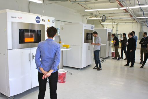
image from:nyc3dp.com
Desktop:
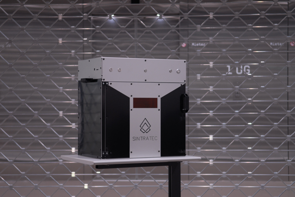
image from:3dprint.com
Fused Deposition Modeling (FDM)→Fused Filament Fabrication (FFF):
This process uses certain melted thermoplastic materials that are joined together to form a shape. As the material hardens, a 3D object is formed.Industrial:
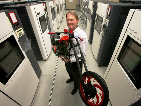
image from:www.3dnatives.com
Desktop:
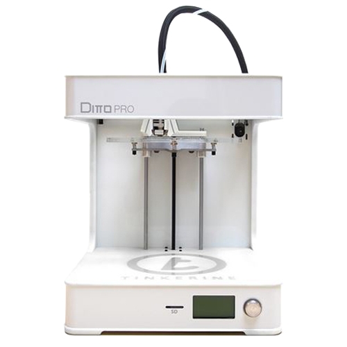
image from:Tinkerine
FFF Demonstration
SlicingPrinter Operation
Applications
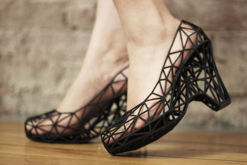
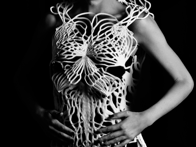
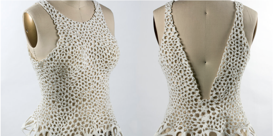
3DX Fashion
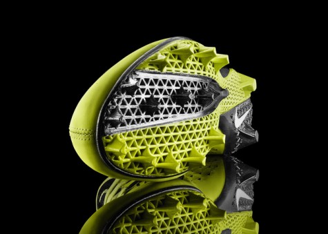
Footwear and apparel company Nike believes 3D printing technology can speed up athletic performance
Image from
3DX Food
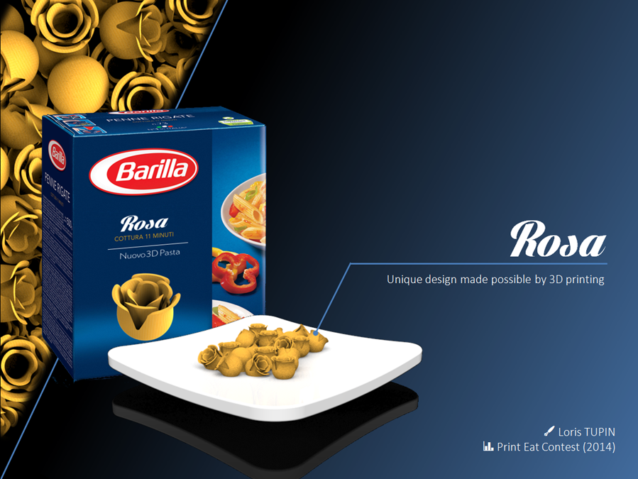
Loris Tupin, a French industrial designer from Maxilly sur Léman, presented the biodynamic model of a flower that, from a bud, changes into a rose during cooking
Image from 3dprintingindustry.com
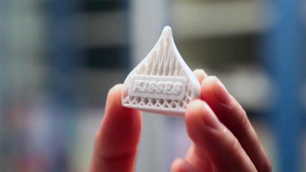
Hershey Unveils 3-D Chocolate Candy Printing Exhibit in Partnership with 3D Systems
Image from 3dprintingindustry.com
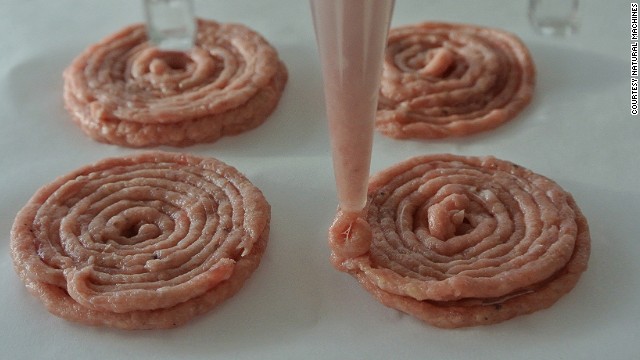
Ingredients are loaded into stainless steel capsules. Load them with beef to print out mini burgers.
Image from cnn.com
3DX Health and Medicine
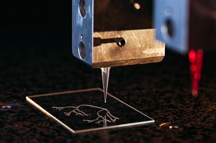
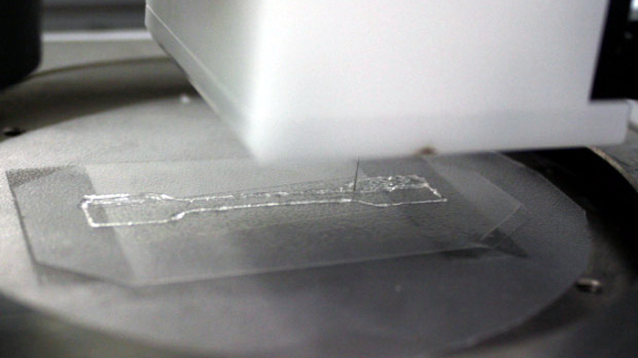
A 3-D printer used by researchers at Harvard University's Wyss Institute creates a model vascular network.
Image from LORI K. SANDERS
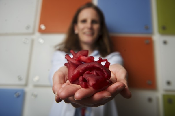
Pediatric cardiologist Laura Olivieri of Children's National Medical Center displays a heart model created by a 3-D printer. (Amanda Voisard/For The Washington Post)
Image from Washington Post
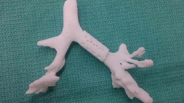
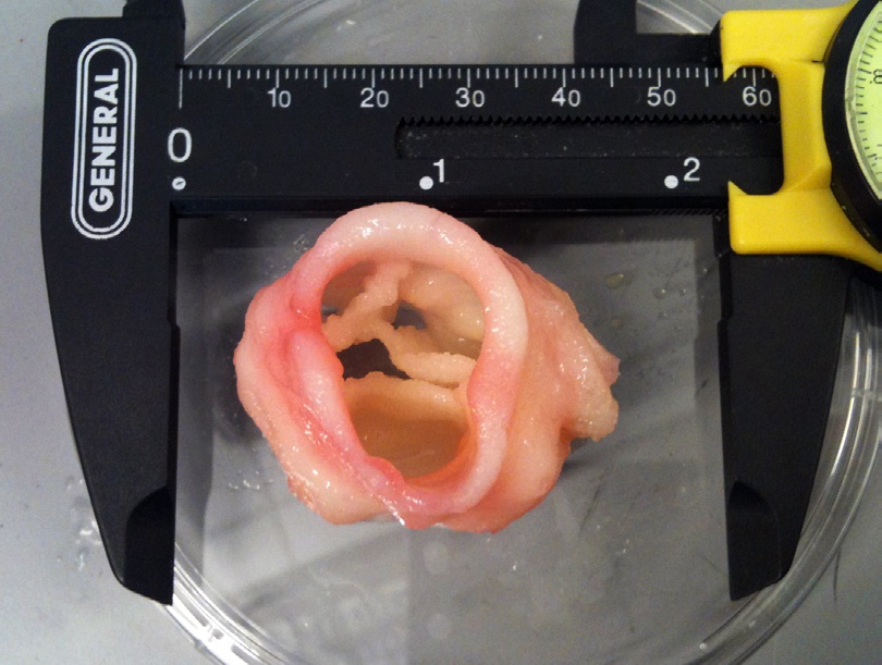
Bioresorbable Airway Splint Created with a Three-Dimensional Printer
Image from The New England Journal of Medicine
3DX Data Visualization
3DX Design
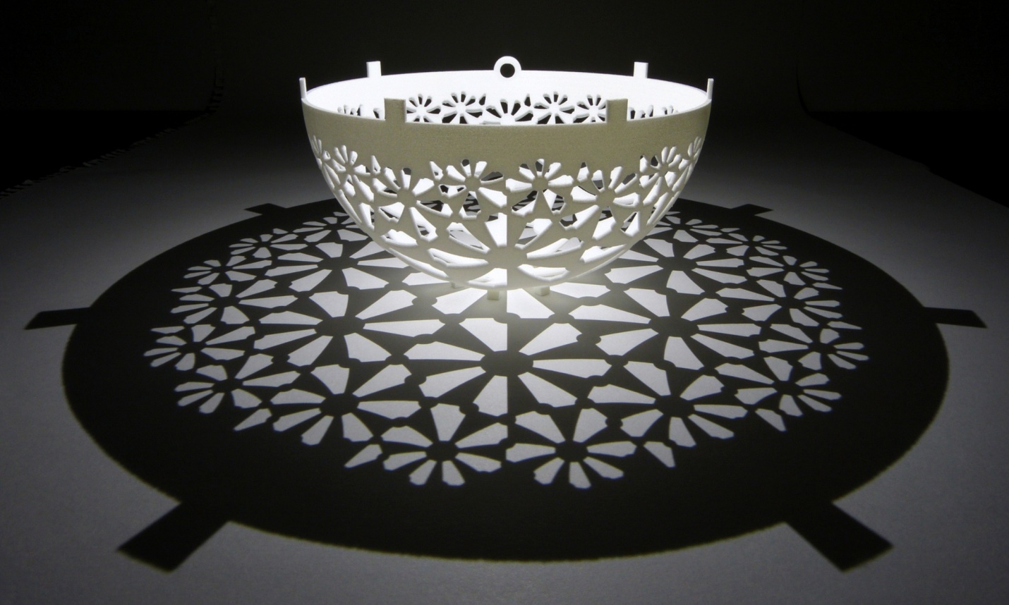
Henry Segerman and Saul Schleimer cast astounding shadows and designs from their designs.
Image from 3dprintingindustry.com
Why we should teach it.
As teachers, we want learning environments and activities that engage and challenge our students. We want to tap into their curiosity, inspire them to see connections between ideas and information and have them use their understanding to creatively problem solve with independence. Our objective is to instill a love of learning, so that they can think critically, communicate effectively, persevere, be intrinsically motivated, be responsible for their own learning outcomes, and find joy in the process.Uses:
- Allows for data visualization.
- Provides tactile feedback.
- Is another means of communication.
- Invites one into the realm of the D.I.Y. ethic.
- Engages students in STEM based projects.
What students get from being involved with 3D Printing:
- Gain understanding of Additive Manufacturing
- Gain experience with Computer Aided Design and Drafting (CADD)
- Participate in process of Rapid Prototyping (RP).
- Participate in process of Reverse Engineering.
- Participate in process of Brainstorming and ideation
- Establish personal Workflows
What kind of tools are available?
- Tinkercad website
30 minutes introductionMore Tinkercad ideas
-
DesignMakeTeach's PERSONALIZE A GIMBAL
Tinkercad Gyro Maker by Mathgrrl (Laura Taalman)
learn to move, align, and group objects and use that knowledge to put together a customized gyro from pre-made pieces.
Choose one small inside hole and use the sliders in the Shape Script to change the number of sides/petals or the amount of twist in the shape. Then Align the small hole with the small blue gyro center and Group them together. For the outside, choose a large shape and customize it to your liking, then Align and Group the large shape with the large hole. Finally, select the customized outer ring together with the orange, yellow, green, and customized blue gyro rings, and Align and Group together to make the final gyro. - Coin Trap
Pause the printer, drop the coin and resume printing
Laura Taalman's Coin Trap Tutorial - Customize the Hinged Buterfly
Ungroup and modify or just start with the hinge - Create your own nets with these hinges or download and print Mathgrrl's (Laura Taalman ) Triangular polyhedra nets
The nets are made to have .2mm (one layer) base thickness plus another .2mm (another layer) for the faces themselves, which are inset just a bit from the base layer so that fold lines develop naturally. Thicker nets did not fold very well and tended to snap along the edges.
Even better, make your own nets.
Look at Origami Heavenfor inspiration. - Explore Mathgrrl's (Laura Taalman ) Tiles for Stellated Octahedron
Optimized to work with the low/.3mm settings - From a drawing to a model (inspired by DesignMakeTeach's SHARPIE TO 3D PRINT IN 30 MINUTES
- Draw a small picture on an index card with a Sharpie marker.
- Take a photo of the drawing
- Upload to your computer
- Open in Inkscape
- Select Path>Trace Bitmap. Click Update and close the pp-up window
- Save file as .svg
- Open a new model in Tinkercad
- Click Import, select file, scale the file
- Download and print
-
DesignMakeTeach's PERSONALIZE A GIMBAL
- 123D Design is free software from Autodesk that allows you to use sketches, lofting, extruding and revolving.
60 minutes introduction and project
123D Design website - Meshmixer
Meshmixer website
Meshmixer 101 videos -
SketchUp—friendly and forgiving 3D modeling software
SketchUp website - 3DSlash website
- OpenSCAD—The Programmers Solid 3D CAD Modeller
OpenSCAD website - Blender website
- Netfabb Studio Basic website
- Kinematics@home website
- Shapeshifter website
- iPad software
- Morphi
- 123D Catch
- 123D Sculpture
- 123D Creature
- Autodesk website
- Fusion 360—
- Autocad—CAD design, drafting, modeling, drawing, and engineering software.
- Inventor
- Maya—Innovative tools for 3D modeling, animation, effects, and rendering.
Modeling Basics
List basic modeling techniques:
- Constructing primitives
- Drawing profiles
- Revolve
- Sweep
- Extrude
- Loft
- Shell
- Slice
- Union
- Intersect
- Subtract
- Fillet
- Chamfer
An Introduction to AutoCAD
Time for Questions
Ideas
- Modify this bridges assignment from BEAM, U.C Berkeley's Science and Engineering Outreach Program
- Adornment challenge: design pendants, bracelets or superhero rings.
- Puzzle Challenge: design a puzzle comprised of 3 interlocking separate objects
- Mr. Potato Challenge: Design a base and modular pieces to attach to the base
- Ball and Socket: Create an articulated hand or foot
- Animation Challenges: Design/Plan a possible stop motion animation that could use printed pieces
- Animation Challenge: Create a face with pieces for the mouth, eyes and eyebrows that can be moved and synced to sound
- Engineering Challenge: Create pieces for Rube Goldberg Contraption
- Design Challenge: Lamp That— turn an object into a lamp.
- Design Challenge: One a Day—ideating, designing, modeling and making. Pick an object like a coffee cup and see how far you can push it
- Design Challenge: Create a 3D model from a younger student's drawing
- Design Challenge: Scan and modify a plush toy
- Engineering Challenge: Recreate a model from the Reuleaux Collection of Mechanical Mechanisms at Cornell University
- Engineering Challenge: Design a machine that implements at least one of the following:
- inclined plane
- lever and fulcrum
- wedge
- screw
- wheel and axle
- Pulley
- Engineering Challenge: Design a robot that can move forward using kinematics
- Engineering Challenge: Design an automaton
- Engineering Challenge: Design the tallest structure with moodular parts
- Science and Engineering Challenge: Egg Drop Holder
Design an Egg Drop Container Using Autodesk 123D - Math: Explore fractals with Sierpinski Tetrahedron and the Menger Sponge
Mathematical Art at Shapeways - Math: Explore hyperbolic paraboloids in a multivariable calculus class
f[u_,v_]:={u,v,u^2-v^2}; scale = 40; radius = 0.75; numPoints = 24; gridSteps = 10; curvesU = Table[ scale*f [u, i ] , {i , -1, 1, 2/gridSteps }]; curvesV = Table[scale*f[j, v], {j, -1, 1, 2/gridSteps}]; tubesU = ParametricPlot3D [ curvesU , {u , -1, 1} , PlotStyle -> radius , PlotPoints -> numPoints ] , PlotRange -> All ] ; tubesV = ParametricPlot3D [ curvesV , {v , -1, 1} , PlotStyle -> radius , PlotPoints -> numPoints ] , PlotRange -> All ] ; Tube [ Tube [ shape of the object than a blank, featureless surface does, and it also communicates mathematical content in terms of the parameterisation. Third, it can be useful to be able to see partially through the surface to other features behind it. 3.3 Mathematica code Here is the code to generate the graphical output shown in Figure 7a, together with the STL file. corners = Graphics3D[Table[Sphere[scale f[i, j], radius], {i, -1, 1, 2}, {j , -1, 1, 2}] , PlotPoints -> numPoints ]; output = Show[tubesU, tubesV, corners] Export["MathematicaParametricSurface. stl", output] - Science: Explore the story of how a child's skull, found in an ancient cave, helped answer one of our oldest questions: Where do we come from? Radio Lab's The Skull
Print the Taung Child Skull - Humanities: Create puppets and re-enact a reading or play.
- CyArk: Spurred by the Taliban's destruction of the 1600-year-old Bamiyan Buddhas in Afghanistan, CyArk was founded in 2003 to ensure heritage sites are available to future generations, while making them uniquely accessible today. Visit the website for 3D lesson plans
- Interdisciplinary: Capture your town, neighborhood, school
- Interdisciplinary: Urban Futures
- Science: Create your own species. Design a fossil or skeleton and determine its scientific classification.
- Science: print out bones, jaws,etc. and have students determine scientic classification
3D Databases
- Thingiverse
- youMagine
- GrabCad
- X 3D Smithsonian
- NIH 3D Print Exchange
- GB3D Type Fossils
The UK repository for digitized type fossil specimens. - African Fossils
African Fossils seeks to increase public knowledge about prehistory by harnessing modern technology. Through digitizing otherwise inaccessible discoveries, the organization is dedicated to creating a growing repository of 3D models of significant fossils and artifacts, thus making them freely accessible to all. - Digital Morphology library
This collection of 3D models of fossils is generated at the National Science Foundation's multi-user CT lab - Smorf
A website that allows you to interactively render crystal structures on-line and buy 3D-printed models at $10/piece. - UK Natural History Museum
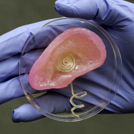
- Human ear from McGill
- TurboSquid
- 3dkitbash
- McMaster-Carr Many parts have downloadable 3D printable parts
Design Process
The Design Process requires- Collaboration
- Research
- Design
- Building
- Testing
- Communication
Basic steps
- Describe the general situation or problem you are trying to solve. Instead of asking "what do you want to design?" ask "why do you want to design that?" and "what problem and or need will your design ultimately be solving?"
- Identify your target population, which group of people will benefit from your project. Is the target population an individual, a group, a specific community, or a larger, identifiable population? Is the target population from a specific location (country, region, town), demographic (age or gender), or other identifying characteristics (health condition or employment)? How is your target population connected?
- Identify requirements and constraints. A requirement is a need or a necessity; it's what a particular product or service should do. A constraint is a restriction on the degree of freedom you have in providing a solution to a need or problem.
- Ask what are the disadvantages of the present solution to the problem?
- Ask what compromises have been made in the present solution?
- Determine if the compromises are necessary?
- Determine if the solution can be improved?
- By taking a new approach
- By making the design more accurate, safer, more convenient, easier to maintain, cheaper, or more attractive
- Determine if you can reduce the costs by eliminating parts, using different materials, changing the way the product is manufactured?
In a nutshell
- Design Step 1: Identify the Need
- Design Step 2: Research the Problem
- Design Step 3: Brainstorm Possible Solutions
- Design Step 4: Engineering Analysis-select the most promising solution
- Design Step 5: Construct a Prototype
- Design Step 6: Evaluate/Manufacture a Final Product-Reiterate
Design Provocations
The following list is attributed to Alex Osborn- Substiture something
- Combine it with something else
- Adapt something to it
- Modify or magnify it
- Put it to some other use
- Eliminate something
- Reverse or rearrange it
Scanning
Capture accurate dimensions of objects and environments so that you can manipulate and or print them.-
123D Catch
You can use Catch on your phone or iPad or use a digital camera and upload the images in the application or on the web version of 123D Catch.Guidelines for capturing
- Rotate around your object, capturing a frame every 5-10 degrees. You are trying to get at least 50% overlap between images. Move the camera at regular intervals and in a predictable pattern (left to right and from top to bottom).
- If using a camera take 30-50 photographs. If using the iPad you are limited to only 40 frames. You will get a ten frame warning. While it seems counter-intuitive, a point and shoot camera may take the best capture because of the algorithm used.
- Decide on a focal length. Once you start capturing frames, avoid zooming in or out. Zooming will distort your capture and will make it impossible for the application to align your set of images. Try to fill the frame with your image.
- Avoid reflective surfaces or objects with glare. Mirrored or transparent surfaces will not work either.
- Before you start, plan out the order in which you will take the frames. Work consistently from high to low, and from left to right. If you keep your sequence consistent you will be able to to identify errors (if they happen) later.
- Consider using some sort of marking system when your subject lacks discernable features. You need four points for registration between any one image and two other images in the collection. Consider using a high contrast tape. Place enough markers so that at least four are always visible from any of the positions you plan to shoot from.
- Your subject should be motionless.
- You can choose the resolution quality when you upload your captures at 123d catch.

After Capturing Images
- Navigate to 123D Catch. Sign in or create an account.
- Select Catch from the list on the left
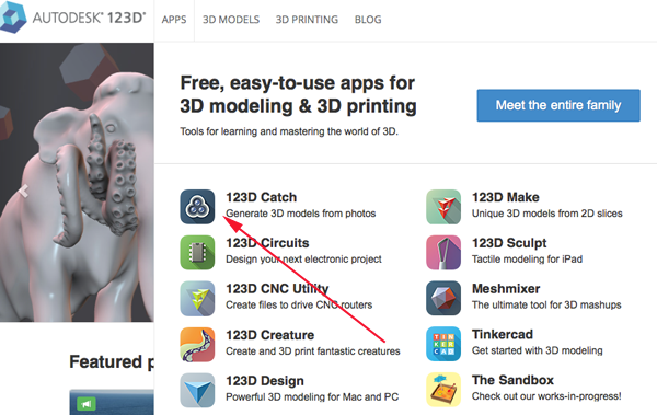
- Select the Launch button:
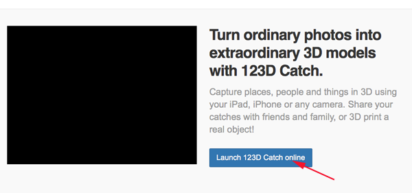
- Click Start a New Project:

- Navigate to or drag your photos into the application. You must have a minimum of 6 and a maiximum of 70
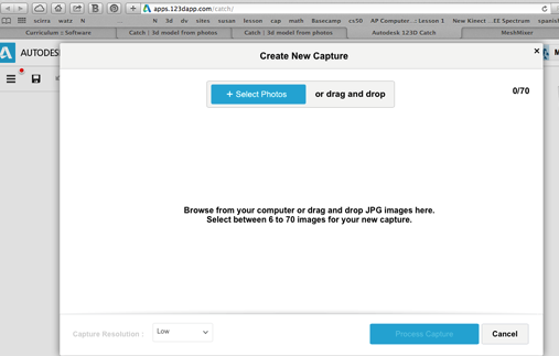
- Wait a bit for the service to process your images.
- View the mesh.
- If you would like to use the 123D Catch editor you may have to download or update the 123D Catch plugin
- You could also download the model and edit in MeshMixer
- 3D Sense
- iSense 3D
- Structure Sensor
- MakerBot Digitizer
Why are we focusing on AutoCAD?
AutoCAD, an application for 2D and 3D computer-aided design (CAD) and drafting, is Autodesk's flagship product and has been available since 1982. As of 2015, AutoCAD is in its thirtieth generation, and collectively with all its variants, continues to be the most widely used CAD program throughout most of the world.
AutoCAD is used across a wide range of industries, by architects, project managers, engineers, graphic designers, and other professionals. AutoCAD allows you to design with precision, use the commandline to speed up design time, add dimensions and constraints and use all basic modeling techniques. You can design as you go, make changes at will, and delete/modify entire sections without effecting the overall process. Once you've learned how to use AutoCAD, you will know what to look for in other CAD programs and learning them will be much easier.
Installation Help
Modeling Basics
An Introduction
Set Up
- Launch AutoCAD.
- Select the acad template:
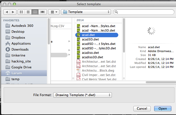
- Make sure CommandLine is visible. If not open it under the Windows menu.
- You need to change the units of the drawing to millimeters.
TypeUN
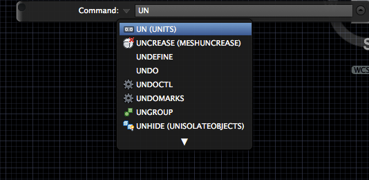
- Set the units to millimeters:
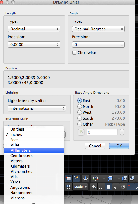
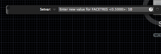
- If you will be 3D printing the model you need to create a higher resolution mesh. Type
facetres

- Set the facetres to 10:
- If you want to keep a record of the profiles turn DELOBJ to 0. This system variable controls whether geometry used to create other objects is retained or deleted.
Type:0 All defining geometry is retained. 1 Deletes profile curves, including those used with the EXTRUDE, SWEEP, REVOLVE, and LOFT commands. Removes all defining geometry for CONVTOSOLID, CONVTOSURFACE, CONVTONURBS, and CONVTOMESH commands. Cross sections used with the LOFT command are also deleted. 2 Deletes all defining geometry, including paths and guide curves used with the SWEEP and LOFT commands. 3 Deletes all defining geometry, including paths and guide curves used with the SWEEP and LOFT commands if the action results in a solid object. Removes all defining geometry for CONVTOSOLID, CONVTOSURFACE, CONVTONURBS, and CONVTOMESH commands. This setting also applies to options in commands such as PEDIT and SPLINE for converting between splines and spline-fit polylines. The range of non-zero values is present to maintain AutoCAD compatibility. -1 Displays prompts to delete profile curves, including those used with the EXTRUDE, SWEEP, REVOLVE, and LOFT commands. Prompts to remove cross sections used with the LOFT command. The original geometry for CONVTOSOLID, CONVTOSURFACE, and CONVTOMESH commands is removed without prompting. -2 Displays prompts to delete all defining geometry, including paths and guide curves used with the SWEEP and LOFT commands. The original geometry for CONVTOSOLID, CONVTOSURFACE, and CONTOMESH commands is removed without prompting. -3 Displays prompts to delete all defining geometry if the resulting entities are a surface of any type. Deletes all original geometry resulting in a solid entity, original geometry for CONVTOSOLID, CONVTOSURFACE, CONVTONURBS, and CONVTOMESH commands is removed without prompting. DELOBJ
Drawing

absolute
relative
polar coordinates
- rectangle
- circle (tan, tan radius)
- polygon
Modifying
- TRIM
TR
- EXTEND
EX
-
OFFSET
OFFSET
-
STRETCH
STR
-
MIRROR
MIRROR
-
ROTATE
ROT
Editing
- COPY
CO
- MOVE
M
- PEDITEdits polylines, objects to be joined to polylines, and related objects. Common uses for PEDIT include joining 2D polylines, and converting lines and arcs into 2D polylines.
PE
-
POLYLINE (Pline)Creates a 2D polyline, a single object that is composed of line and arc segments.
PL
- REGIONRegions are solid 2D shapes. You can combine existing regions into a single, complex region.
REG
Regions can be used for combining simple objects into more complex ones with Boolean operations. - EXPLODEYou can convert a compound object, such as a polyline, dimension, hatch, or block reference, into individual elements. For example, exploding a polyline breaks it down to simple lines and arcs.
EXP
2D to 3D
-
presspullDynamically modifies objects by extrusion and offset.
PRESSPULL
-
EXTRUDECreates a 3D solid or surface by extending a 2D or 3D curve. Extrusions can extend in the Z direction or be set to taper or follow a path. You can extrude an open or closed object to create a 3D surface or solid.
EXT
- REVOLVECreates a 3D solid or surface by sweeping an object around an axis.
REV
Open profiles create surfaces and closed profiles can create either a solid or a surface. The MOde option controls is a solid of surface is created. -
SWEEP Creates a 3D solid or surface by sweeping a 2D or 3D object or subobject along a path.
SWEEP
-
SHell
SOLIDEDIT:body:Sh
- OFFSETEDGE Creates a closed polyline or spline object that is offset at a specified distance from the edges of a selected planar face on a 3D solid or surface.
offsetEdge
Boolean Operations
- UNIONCombines two or more 3D solids, surfaces, or 2D regions into a single, composite 3D solid, surface, or region.
UNI
- INTERSECTCreates a 3D solid, surface, or 2D region from overlapping solids, surfaces, or regions.
INT
- SUBTRACT Creates as a new object by subtracting one overlapping region or 3D solid from another.
SUBTR
Primitives
- BOX
- CONE
- CYLINDER
- PYRAMID
- SPHERE
- TORUS
- WEDGE
- POLYSOLID
Afternoon Challenge
