Semiconductor device with 3 leads:
There are two types of transistors: bipolar and field-effect transistors (FETs). Unlike bopolar transistors, the leads of FETs are referred to as gate, source and drain.
Bipolar transistors can be divided into two categories: NPN and PNP.NPN transistors act like normally opened swtches. PNP transistors act like NC switches.
- Emitter
- Base
- Collector
There are two types of transistors: bipolar and field-effect transistors (FETs). Unlike bopolar transistors, the leads of FETs are referred to as gate, source and drain.
Bipolar transistors can be divided into two categories: NPN and PNP.NPN transistors act like normally opened swtches. PNP transistors act like NC switches.
Function
Can amplify the current or can be used as a switch.Operating Values
These values vary and you must refer to the datasheets.
Bipolar Transistors are composed of three layers:
Layers are formed by doping silicon with traces of impurities. Silicon treated with Boron produces negative type material. It is negative because it has a surplus of electrons. Doping the silicon with Phosphorous produces positive material, or material with a surplus of electron holes.
Silicon transistors are considered semiconductors because they conduct only a small amount of current unless a change in voltage is applied at a juncture.
When current is applied to the input layer, or the emitter of an NPN transistor, electrons flow to the P-type base and fill the positive material, or electron holes. When the holes are filled, the material no longer conducts current. But when a small voltage is applied to the control layer, or base, that current will produce additional holes which in turn allows current to flow from the emitter through the base to the collector.
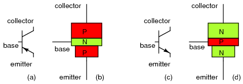
The difference between a PNP transistor and an NPN transistor is the polarity, or proper biasing of the junctions. Transistors restrict the amount of current passed according to a smaller, controlling current. The main current from collector to emitter (PNP) or from emitter to collector (NPN) depends on the type of transistor it is. The small current that controls the main current goes from base to emitter (PNP), or from emitter to base (NPN), depending on the kind of transistor it is.
The arrow always points against the direction of electron flow.

Bipolar transistors are called bipolar because the main flow of electrons through them takes place in two types of semiconductor material: P and N, as the main current goes from emitter to collector (or vice versa). Two types of charge carriers: electrons and holes, comprise the main current through the transistor.
All currents must be going in the proper directions for the device to work as a current regulator. The small, controlling current is usually referred to as the base current because it is the only current that goes through the base wire of the transistor.
The large, controlled current is referred to as the collector current because it is the only current that goes through the collector wire.
The emitter current is the sum of the base and collector currents, in compliance with Kirchhoff's Current Law.
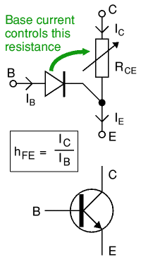
Transistors are not a good choice when switching large currents (> 5A). When switching large currents, you need to use relays.
- An Input Layer, the emitter
- A Control Layer, the base
- An Output Layer, the collector
Layers are formed by doping silicon with traces of impurities. Silicon treated with Boron produces negative type material. It is negative because it has a surplus of electrons. Doping the silicon with Phosphorous produces positive material, or material with a surplus of electron holes.
Silicon transistors are considered semiconductors because they conduct only a small amount of current unless a change in voltage is applied at a juncture.
When current is applied to the input layer, or the emitter of an NPN transistor, electrons flow to the P-type base and fill the positive material, or electron holes. When the holes are filled, the material no longer conducts current. But when a small voltage is applied to the control layer, or base, that current will produce additional holes which in turn allows current to flow from the emitter through the base to the collector.

The difference between a PNP transistor and an NPN transistor is the polarity, or proper biasing of the junctions. Transistors restrict the amount of current passed according to a smaller, controlling current. The main current from collector to emitter (PNP) or from emitter to collector (NPN) depends on the type of transistor it is. The small current that controls the main current goes from base to emitter (PNP), or from emitter to base (NPN), depending on the kind of transistor it is.
The arrow always points against the direction of electron flow.

Bipolar transistors are called bipolar because the main flow of electrons through them takes place in two types of semiconductor material: P and N, as the main current goes from emitter to collector (or vice versa). Two types of charge carriers: electrons and holes, comprise the main current through the transistor.
All currents must be going in the proper directions for the device to work as a current regulator. The small, controlling current is usually referred to as the base current because it is the only current that goes through the base wire of the transistor.
The large, controlled current is referred to as the collector current because it is the only current that goes through the collector wire.
The emitter current is the sum of the base and collector currents, in compliance with Kirchhoff's Current Law.
NPN transistor

- The base-emitter junction behaves like a diode.
- A base current IB flows only when the voltage VBE
across the base-emitter junction is 0.7V or more.
- The small base current IB controls the large collector current Ic.
- The collector-emitter resistance RCE is controlled by the base current IB:
- IB = 0 RCE = infinity transistor off
- IB small RCE reduced transistor partly on
- IB increased RCE = 0 transistor full on ('saturated')
- IB = 0 RCE = infinity transistor off
Transistors are not a good choice when switching large currents (> 5A). When switching large currents, you need to use relays.
A transistor as switch


If there is no current through the base of the transistor, the transistor shuts off the controlled current like an open switch and prevents current through the collector. A base current, turns the transistor on like a closed switch and allows a proportional amount of current through the collector. Collector current is primarily limited by the base current, regardless of the amount of voltage available to push it.

The image above shows the two current paths through a transistor. You can build this circuit with two standard 5mm red LEDs and any general purpose low power NPN transistor. The small base current controls the larger collector current.
When the switch is closed a small current flows into the base (B) of the transistor. It is just enough to make LED B glow dimly. The transistor amplifies this small current to allow a larger current to flow through from its collector (C) to its emitter (E). This collector current is large enough to make LED C light brightly.
When the switch is open no base current flows, so the transistor switches off the collector current. Both LEDs are off.
When a transistor is used as a switch it must be either OFF or fully ON. In the fully ON state the voltage VCE across the transistor is almost zero and the transistor is said to be saturated because it cannot pass any more collector current Ic. The output device switched by the transistor is called the load.
The transistor's voltage ratings may be ignored unless you are using a supply voltage of more than about 15V.
Protection diode

If the load is a motor, relay or solenoid (or any other device with a coil) a diode must be connected across the load to protect the transistor from the brief high voltage produced when the load is switched off.
To switch on the load when output is high use a NPN. If you need the opposite action, with the load switched on when the output is low (0V) use a PNP transistor.
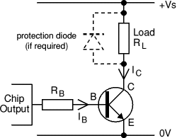
- The transistor's maximum collector current Ic(max)
must be greater than the load current Ic.
load current Ic = supply voltage Vs load resistance RL - The transistor's minimum current gain hFE(min)
must be at least five times the load current Ic divided
by the maximum output current from the IC.
hFE(min) > 5 × load current Ic max. IC current - Choose a transistor which meets these requirements and make a note of
its properties: Ic(max)
and hFE(min)
- Calculate an approximate value for the base resistor:
RB = Vc × hFE where Vc = IC supply voltage
(in a simple circuit with one supply this is Vs)5 × Ic
For a simple circuit where the IC and the load share the same power supply (Vc = Vs) you may prefer to use: RB = 0.2 × RL × hFE
Then choose the nearest standard value for the base resistor. - Finally, remember that if the load is a motor or relay coil a protection diode is required.
Choosing a suitable PNP transistor
The circuit diagram shows how to connect a PNP transistor, this will switch on the load when the IC output is low (0V). If you need the opposite action, to switch the load on when the output is high use an NPN transistor.
Darlington pair
A Darlington pair is two transistors connected together so that the current amplified by the first is amplified further by the second transistor. The overall current gain is equal to the two individual gains multiplied together:Darlington pair current gain, hFE = hFE1 × hFE2
A Darlington pair behaves like a single transistor with a very high current gain. It has three leads (B, C and E) which are equivalent to the leads of a standard individual transistor. To turn it on there must be 0.7V across both the base-emitter junctions which are connected in series inside the Darlington pair, therefore it requires 1.4V to turn on the pair.
A Darlington pair is sufficiently sensitive to respond to the small current passed by your skin and it can be used to make a touch-switch as shown in the diagram. For this circuit which just lights an LED the two transistors can be any general purpose low power transistors. The 100k resistor protects the transistors if the contacts are linked with a piece of wire.

Sensors
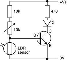
LED lights when the LDR is dark
The 10kΩ fixed resistor protects the transistor from excessive base current (which will destroy it) when the variable resistor is reduced to zero. To make this circuit switch at a suitable brightness you may need to experiment with different values for the fixed resistor, but it must not be less than 1kΩ.
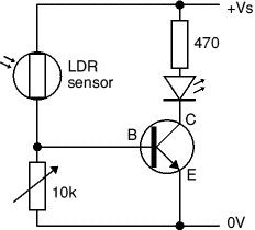
LED lights when the LDR is bright
The switching action of this circuit is not particularly good as there will be an intermediate brightness when the transistor will be partly on (not saturated). In this state the transistor is in danger of overheating unless it is switching a small current. An LED does not present a problem because the current is low, but with a lamp, motor or relay, your transistor could cause overheat.
Other sensors, like a thermistors, flex and force sensors, can be used with this circuit, but they may require a different variable resistor. You can calculate an approximate value for the variable resistor (Rv) by using a multimeter to find the minimum and maximum values of the sensor's resistance (Rmin and Rmax):
Variable resistor, Rv = square root of (Rmin × Rmax)
For example an LDR: Rmin = 100Ω, Rmax = 1MΩ, so Rv = square root of (100 × 1M) = 10kΩ.
//Inverters

When the output signal (voltage) is the inverse of the input signal you have an inverter.
You can use logic IC's to create inverters or NOT gates, but if you only need one inverter you can use a transistor.
Any general purpose low power NPN transistor can be used. For general use RB = 10kΩ and RC = 1kΩ, then the inverter output can be connected to a device with an input impedance (resistance) of at least 10kΩ such as a logic IC or a 555 timer (trigger and reset inputs).
If you are connecting the inverter to a CMOS logic IC input (very high impedance) you can increase RB to 100kΩ and RC to 10kΩ, this will reduce the current used by the inverter.
//Multiple LEDs
 Each digital pin on the Arduino has an internal pull up resistor that can be turned on and off using the digitalWrite() command when it is configured as an output. When it is HIGH, 5V sent to the pin and can deliver 40mA of current. This is adequate to power an LED, but most devices that you will want to power will require more current. A device that is trying to draw more current than this can cause the Arduino to shutdown and could easily damage the chip. There are many methods to increase the current that can be sources on an output pin. When a relatively small amount of additional current is needed, a 2N3904 NPN Transistor (or any similar type) can be used to accomplish this. In this example, you will connect four LEDs to one output pin using this simple transistor circuit.


