FreeCAD is an amazing program, and this introduction will barely touch on all that you are capable of accomplishing with it. FreeCAD is a general all-purpose 3D modeling application. The interface is divided into a series of Workbenches, which allows you to change the interface contents to display all or only the tools necessary for your specific task, or group of tasks.
Think of the interface as a container, with a menu bar, a 3D view area, and side panels for displaying the scene contents or object properties. All the contents of these panels can also be modified depending on the workbench.
When you first open the application, you will see the general workbench, or the complete workbench. The complete workbench is very handy for discovering FreeCAD more easily.

The default Navigation is CAD Navigation, where navigating the space is similar to other CAD programs, with the exception of rotating. Left mouse click lets you select the object. Holding CTRL lets you add to the selection. The middle mouse allows you to pan and zoom. To rotate, hold the middle mouse button down then add the left mouse down then drag to rotate.
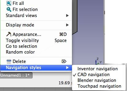
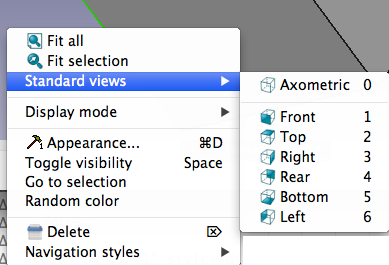
You can also CTRL click to select a view from the context menu:

You can also select Inventor Navigation. Here to select an object hold CTRL+LEFT mouse click. Click the left mouse button to move the object around. Zoom in and out with the scroll wheel or hold the middle mouse button then click the left mouse button. Click and drag with the left mouse button to rotate
The third navigation object is Blender Navigation. Left mouse button to select an object. Hold shift and click the middle mouse button to pan. Mouse wheel to zoom. Click and drag with the middle mouse button to rotate.
When you first open the application, you will see the general workbench, or the complete workbench. The complete workbench is very handy for discovering FreeCAD more easily.

The default Navigation is CAD Navigation, where navigating the space is similar to other CAD programs, with the exception of rotating. Left mouse click lets you select the object. Holding CTRL lets you add to the selection. The middle mouse allows you to pan and zoom. To rotate, hold the middle mouse button down then add the left mouse down then drag to rotate.
You can also CTRL click to select a view from the context menu:

You can also select Inventor Navigation. Here to select an object hold CTRL+LEFT mouse click. Click the left mouse button to move the object around. Zoom in and out with the scroll wheel or hold the middle mouse button then click the left mouse button. Click and drag with the left mouse button to rotate
The third navigation object is Blender Navigation. Left mouse button to select an object. Hold shift and click the middle mouse button to pan. Mouse wheel to zoom. Click and drag with the middle mouse button to rotate.
Part Module
- Download FreeCad and install
- Select the Part Module from the Start dropdown menu at the top

Here are the tools associated with the Part Module Workbench

- Select a New Empty Document

- This is the new view:

- The Part Workbench uses solid modeling. You work with primitive shapes like cubes, cylinders, spheres and cones to construct your geometry by combining them, subtracting one shape from the other, or intersecting them. You can also apply transformations on shapes, like applying rounds or chamfers on edges. These tools are also in the Part Workbench.
Click on the Box Button
- You can change the dimensions by selecting it either in the 3D space, or by clicking it in the Project tab to the left, then
Click on the Data tab at the bottom, and change values for Height, Length and Width to 30mm, 20 and 20

- To see the changes you can rotate the cube. Hold down the center button, then add the left and drag to rotate.
- Create a second box the same way, but with values 28, 18 and 18mm. By default this box will be superimposed on the first one.

- You'll now subtract the second box from the first. Select the first shape first (named Box), then the second one (named Box001), the selection order is important!

- On the Part Workbench toolbar, click on the Cut tool

- Rotate to see the Boolean difference

- You can toggle open the cut, select one of the boxes and make modifications to the properties.

- Want the cut from the center, adjust the position

- To add a fillet, select the fillet tool, click the appropriate edges and press the OK button


- To be able to print the form you'll have to convert it to a mesh and then export it:

- Once it is a mesh, you can analyze it:

- Then you can export as an stl

